Efficient height reduction over-the-cell channel
router
Engineering, National University of Singapore, 10 Kent Ridge Crescent, Singapore 05 1 1
Science, National Chiao Tung University, Hsinchu, Taiwan 300, P.-Y. Hsiao is with the Department of Computer and Information P.-W. Shew
P.-Y. Hsiao Y.-C. Lim
This work was supported in part by the National Science Council, Republic Of China, under grant NSC84-2213-EW-017.
Indexing terms: Algorithms, Network routing, Over-the-cell channel routers, VLSI
Abstract: The authors present a new algorithm for both two-layer and three-layer over-the-cell channel routing in the standard cell VLSI design. The approach exploits vacant terminals on the channel boundary effectively. It considers the fol- lowing factors simultaneously to select net seg- ments for routing over the cells: density distribution in the channel, the longest path in the vertical constraint graph, elimination of cycles in the vertical constraint graph and reduction in maximum cliques in the horizontal constraint graph. With respect to the PRIMARY 1 bench- mark examples, the router achieved a 41.3% improvement over the Greedy channel router (one without using over-thecell area) for a two-layer routing model and a 61.0% improvement for a
three-layer routing model. This outperforms all previous algorithms. power and ground - line chonnel helght = 3 tracl
routing between two rows of standard cells (i.e. in the channel area) within a circuit.
Many channel routing algorithms have been proposed and they can produce solutions very close to optimum (e.g. the Greedy channel router [l]). Researchers have also proposed the use of the area over the standard cells for routing in second (M2) and third (M3) metal layers (the first metal (Ml) is usually used for routing within the cell). Such routing style is known as over-the-cell channel routing. Fig. l b illustrates such a routing style. Eflicient utilisation of the area over the cells can reduce the layout area substantially. The reduction in chip area with this approach is even more significant in today's fabrication technology, as more metal layers are available for routing.
It has been shown that the channel routing problem is NP-hard [2]. Over-theall (OTC) channel routing is a more general case of the channel routing problem, hence it is obviously NP-hard too. A number of heuristics have been proposed [3-121 for either a two-layer (i.e. using only M2) or a three-layer (i.e. using both M2 and M3) OTC channel routing model. After the introduction of using vacant terminals in OTC routing [8], recent OTC channel routers can reduce the channel height by 30% for a two-layer model and 50% for a three-layer model (see Table 1).
In this paper we present a new algorithm which we have implemented for two-layer and three-layer OTC 1 Introduction
In VLSI layout design using standard cells, channel routing is a crucial problem which has been studied extensively. A good routing solution should complete the connections in the channel with the minimum number of tracks. This will minimise the channel height, thus reducing the total chip area. Fig. l a shows an example of
feedlhmgh
i
uppercd(ro*rI I I I
a b
Fig. 1
a Traditional channel routing
Typical channel routing problem
b Over-the-xll channel routing c Symbolic representation
'
0 3 L 1, 5u0
C
channel routing problems. We call our program HERO-V (HEight Reduction Over-thecell channel router without using
vias
over the cell area).ne
0 IEE, 1995Paper 1988E W O ) , first received 31st January 1994 and in final revised form 30th January 1995
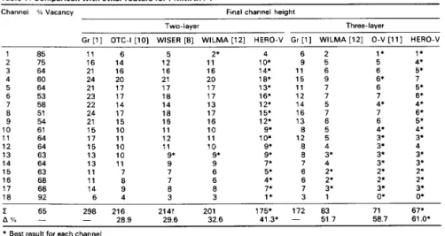
Table 1 : Comparison with other routers f o r PRIMARY 1
Channel % Vacancy Final channel height
Two-layer Three-layer
Gr [l] OTC-I [lo] WISER [8] W I L M A [12] HERO-V Gr [l] W I L M A [12] 0 - V [ll] HERO-V
1 85 2 75 3 64 4 60 5 64 6 53 7 58 8 51 9 54 10 61 1 1 64 12 64 13 63 14 64 15 63 16 68 17 68 18 92 1 1 6 16 14 21 16 24 20 21 17 23 17 22 14 24 17 21 15 15 10 17 1 1 15 10 13 10 13 1 1 1 1 7 1 1 8 14 9 6 4 5 12 16 21 17 18 14 18 16 1 1 12 1 1 9* 9 7 7 8 3 2 ' 1 1 16 20 17 17 13 17 16 10 1 1 10 9 ' 9 6 6 8 3 4 6 2 10' 9 5 14' 1 1 6 18' 15 9 13' 1 1 7 16* 12 7 12. 14 5 15' 16 7 12; 13 6 9. 8 5 10' 12 5 9. 8 4 9 ' 8 3' 7 ' 7 4 5* 6 '2 4* 6 2' 7* 7 3. 1 * 3 1 1 ' '1 5 4* 6 5. 6' 7 6 5' 7 6' 4. 4' 7 6' 6 5' 48 4' 3. 3' 3 ' 4 3 ' 3' 3* 3' 2 ' 2' 2 ' 2' 3. 3' O* 0' E 65 298 216 214t 201 1751 172 a3 71 67' 58.7 61.0. A - - 28.9 29.6 32.6 41.3' - 51 7
* Best result for each channel t Addition error in References 8 and 9
rithm has a generic nature in that it may be further extended to multiple-layer OTC channel routing. Our approach eficiently selects a subset of net segments to be routed over the cells with consideration of density dis- tribution in the channel, and by making use of the vacant terminals it reduces the longest path in the vertical con- straint graph, as well as the maximum cliques in the hori- zontal constraint graph. At the same time, cycles in the vertical constraint graph are eliminated as much as pos- sible. We have tested our algorithm with a number of benchmark examples to verify its effectiveness. For the PRIMARY 1 example, our algorithm achieved 41.3% and 61.09" reduction in total channel height for two-layer and three-layer OTC routing models, respectively. It out- performs all previous algorithms.
2
The OTC channel routing is restricted by the number of metal layers available in the IC fabrication. In this paper, we assume that the intracell connections are done in the polysilicon and the first metal ( M l ) layer. The feed- through is made in the M1 layer too. The power and ground lines are laid in the second metal (M2) layer along the centre of the area over the standard cells. These lines divide the over-the-cell (OTC) area into two halves and the cell height permits us to route six tracks in the M2 layer over each half. The OTC area in the third metal (M3) layer is not divided, but for simplicity we split the area into two halves and only route, at most, seven tracks over each half. Vias may or may not be made in the OTC area, depending on the fabrication technology. In our current implementation, we assume vias are not allowed so OTC routing in M2 and M3 layers must be planar.
As for routing in the channel region, we adopt the tra- ditional HV and HVH models for two-layer and three- layer channel routing. Under these channel routing models, horizontal and vertical wire segments are used exclusively in alternating metal layers. We make use of doglegs to complete the channel routing while keeping the final channel height as low as possible. Fig. l b illus- trates this physical routing model. Discussion on other
Physical model for OTC routing
294
OTC routing models can be found in Reference 5 . Fig. I C shows a symbolic representation of the same problem as in Figs. l a and b.
3 Terminology and notation
Amongst the N,,, nets in a given channel, some may be multiterminal, i.e. a net consisting of more than two ter- minals. The approach in this paper first decomposes all multiterminal nets into modified two-terminal net seg- ments adjacent at common terminal locations. Each pair of terminals defines a net segment which will either be routed in the channel or in the OTC area. Thus net ni = {t,
,,
t , 4 , t , ,} (Fig. 2), after being decomposed, gives us the segments si = {si, si, 2 } , where ts.c refers to the terminal on row s (TOP or BOTTOM) at column c ; si, =(Ii.
j , ri, where li. and ri, denote the left and right column of the net segment si. j ." I ( t l ) ) n , ( t t , 7 ) S , , l I S ! 2 "I ( 1 b.4 column 1 2 3 4 5 6 7 Fig. 2
with net segments si,
,
and si,Decomposing multiterminal net, n j . into 2 two-terminal nets
Next we define the set of critical columns, c, = {c,:: (1
<
i<
N)[D(c,J = D o ] } , where N is the number of columns in the channel, D(c) is the local density at column c (i.e. the number of net segments intersecting column c), and the channel density, Do = max [D(c)]. Our approach considers the horizontal constraints in the channel by analysing the modi$ed horizontal constraint graph (MHCG). MHCG is an undirected graph G,, =(V', E,) where V' = {ui, j : ui, represents the modified net segment si, j } and E,, = {(vi, j , uk, ,): si, intersects s k , ,
,
i # k } . The vertical constraints, however, are considered
by analysing the longest path in the vertical constraint
graph (VCG). VCG is a directed graph, G , = (V, E,) where V = { v i : vi represents net i} and E, = {(ui, uj):
(31
<
c<
N) [TopNet(c) = i, BottomNet(c) = j, i # j]}. TopNet(c) and BottomNet(c) are the top terminal net and bottom terminal net at column c, respectively.4 Reduction in channel height
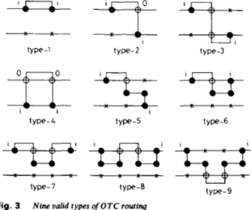
As mentioned earlier, OTC channel routing can reduce the channel height of a circuit. Fig. 3 depicts nine valid OTC routing types for a net segment si j . These types are not exhaustive but are the ones considered in our algo- rithm. Note that we allow combinations of these types for any net segment remaining in the channel. In Section 4.1,
we discuss the factors which affect the channel height of a channel routing solution (without OTC routing). Then we describe the heuristic cost function befitting our con- sideration of all these factors in Section 4.2 and we give a
summary of our algorithm in Section 5. To aid the description of our algorithm, we trace the execution of our program for a simple problem in Fig. 4.
type-1 type-2 type-3
-
type-4 type-5 t ~ ~ e - 6
-*5z
type-7 tyPe-8 tyPe-9Fig. 3 Nine ualid types of OTC routing
4.1 Lower bound for channel height
The first lower bound for channel height is the channel density d. In earlier algorithms (e.g. in References 4-7 and lo), the reduction in channel density was the ultimate
goal. However, without considering other factors, they did not perform well. The second lower bound is the length of the longest path in VCG 1. It is possible to
reduce I by doglegging [13] or making OTC routing as illustrated in Fig. 4c. The weight w2 in our heuristic cost function is improvised to achieve the lowest value of 1. In
addition to max (d, r), Brown and Rivest [I41 have shown
that for a two-terminal net routing problem t 2 -(w - n)
+
rJ{(w - n)’+
2m)l is a lower bound if nets are allowed to cross the initial routing window (w is the width of the window, n is the number of nets and m is the number of nontrivial nets, i.e. those that need to be ‘moved‘). Following the argument, it is easy to see that t 2 m/(w - n) if the nets are not allowed to cross the window. With the concept of channel flux, Baker et al. [l5] proposed max ( J d) to be the lower bound. Lee and Leong [I61 suggested that for any path P in VCG,ifs,
is the set of nets not in P but intersect every element in P,then T = max ( I PI
+
I clique(Sp)1
) is a tighter lower bound for the channel height. We shall re-examine the lower bound with zone representation [17] and VCG fora multiterminal net routing instance. Rigorous details are omitted in the following for the sake of brevity.
I E E Proc.-Comput. Digit. Tech., Vol. 142, No. 4, July 1995
The zone representation does characterise the dogleg- free restricted Manhattan routing model for two-terminal nets but is not accurate enough for more general multi- terminal net problems with doglegging. Adjacent subnets can either be routed on the same or different track (by adding doglegs), thus occupying one track for the former but two tracks for the latter. This can be represented more accurately by a reduced zone representation (RZR),
as illustrated in Fig. 56. The zone representation was
originally defined for open interval (zl. z2] where z1 and zz are the positions of two terminal columns acting as the
boundary of the zone. In RZR, the interval (zl, zz) is used instead. Observe that a pair of adjacent subnets which are not merged in the routing solution will have the right subnet appearing in the left zone, e.g. subnet 26 in Fig. 56. Construction of the RZR requires a prior knowledge
of whether each pair of adjacent subnets is merged in the final channel routing solution. Fortunately, we can obtain better insight from the VCG. Let us construct a
reduced vertical constraint graph (RVCG) by merging all
subnet nodes (belonging to the same net) on the VCG into a single node subject to the condition of not elon- gating the vertical constraint path. Fig. 5c shows the RVCG of the channel routing instance in Fig. 5a. Note that subnets 4a and 46 (not shown) are merged, but 2a
and 26 are not. If we merge 2a and 26, then 1 will increase from three to four. Whichever pair of subnets is merged in the RVCG, they will also be merged in the RZR. The RZR density d, is then determined. Finally, we have t , = max (d, , T) as an improved lower bound. In fact this is the best known lower bound for the channel routing problem. In Fig. 5, d, = 4 and T = 3 thus giving t, = 4.
Fig. 5a shows an optimal solution which requires four
tracks to complete the routing.
As we allow doglegging, we consider the channel hori- zontal contraints with MHCG. To reduce the value of
d,, we introduce the cost w j in our heuristic cost func- tion described in the following section. The combination of weights w2 and w3 attempts to lower the value oft, in the final channel routing stage. Next, cycles may occur in a VCG. Without doglegging, a channel with a cyclic VCG does not have a routing solution. In fact cycles in the VCG pose. a problem to many channel routers. Fig.
46 shows how OTC routing can provide a means of
breaking a cycle. We give preference to candidates that can break any cycle. This is reflected by w1 in our cost function.
4 2 Cost function for OTC routing
With all the valid OTC routing candidates, we construct a candidate set,
where pi, is the OTC routing type for net segment si, j . Two candidates may be conflicting, i.e. routing both over the cells will cause a short circuit. For example, type-I of Net 2 and type-2 of Net 3 in Fig. IC are conflicting. We use f,(si. j , , pi. j ) to denote the number of candidates con- flicting with the candidate (si. j , pi. j ) . Minimal conflicts allow more net segments to be routed OTC. Now a proper candidate in c, has to be selected for routing OTC in every iteration. To make this selection, we device four weights below to calculate the criticality of each candi- date.
w1 = 1 if routing (si, j , pi, OTC will break a cycle
= O otherwise (1)
9
U'm
0"0
=@-@ U 8 D9
W ... W o m m o o r . p . 0 - 0 0 -R S -R -Rf C 8 8
0 0 0 0 0 0 0 0 0 0 0 0 0 0 0 0 0 0 0 0 ^ ^ ^ ^ -. . . C - N V l m m L Z Z ?- - - -
ti
f U Nw2 = 0 if ni # L,, 121, - I ,
-
1I
I ,+
1 = I - otherwise (3) (4)Here L,, is the longest path in the vertical constraint graph and I , is the length of the longest path, while 1, is the relative position of the candidate net in the longest path, d(u, G) is the degree of vertex U in the undirected
graph G.
0 1 5 L 2 3 2 0 Fig. 5A Channel routing instance
R Z R ,
Fig. 5 8 Reduced zone representation
RVCG
2b Fig. SC Reduced vertical constraint graph
5 Summary of our algorithm
The essence of our algorithm lies in the selection of net segments to be routed over the cells. The algorithm can be summarised in the following steps:
( a ) Decompose multiterminal nets: All multiterminal nets are decomposed into two-terminal nets adjacent at common terminal locations thus giving us a set of two- terminal net segments.
( b ) Determine critical columns and OTC candidates: The channel density is determined before the set of criti- cal columns c, is constructed. From the critical columns and based on the valid OTC routing types (see Section
4.1), we construct a set of OTC candidates which are not
conflicting with those already routed OTC net segments. Conflicting ones are discarded and will not be considered further. When the corresponding net segment of the selec-
I E E Proc.-Comput. Digit. Tech., Vol. 142, No. 4, July I995
ted candidate is removed from the channel in step (d), the column densities within its span are decreased by one and more columns become critical. Hence c, and, simi- larly, the set of OTC candidates are updated in sub- sequent iterations.
( c ) Determine L,, andfind cycle-breaking nodes in VG:
We construct the vertical constraint graph VG and deter- mine the set of longest path(s) LvG. If cycles occur, we find the valid candidates that can break a cycle in VG, if they are routed OTC.
(d) Weight assignment and OTC candidate selection: The criticality of each OTC candidate is calculated by summing the four weights described in Section 4.1. The
most critical net segment will be selected. In the case of equal weights, we choose the left-most candidate.
(e) Track assign selected OTC candidate: The selected
candidate is then track-assigned in the OTC area. We do not perform the actual routing in this step because assigning a new selected net segment may involve shifting previously assigned segments. The final geometrical routing will be done in step (9). Next, the corresponding net segment of the selected candidate is removed from the channel.
(f) Repeat step ( b ) until no more net segment can be routed ouer the cells: Once a critical net segment is removed from the channel in step (e), we update the column (channel) densities. The VCG, as well as the MHCG will also be updated.
(g) Route track assigned OTC net segments: Assign- ment of geometrical track location for each OTC net segment is finalised after the above iteration. The OTC net segments are routed accordingly here. This step marks the end of the OTC routing phase.
(h) Route remaining net segments in channel: Net seg- ments not routed OTC will be routed in this step using conventional channel routing techniques.
The differences between two-layer and three-layer OTC routing occurs mainly in steps (b) to (d). For each layer of metal available a disjoint candidate is selected, hence in three-layer OTC routing an M2 candidate and an M3 candidate will be selected. The enumeration of an OTC candidate set and its maintenance in step (b) contributes the highest computational complexity. The overall OTC routing is of the order of O(n2kZZ) where n is the number of net, k is the maximum number of net interval of a net and I is the maximum length (in terms of columns) of a net interval.
After the OTC routing phase, the remaining net seg- ments are routed in the channel by a conventional channel router. We use an HV model for two-layer routing and an HVH model for three-layer routing in the channel. The routing problem left in the channel is much simplified as most cycles and vertical constraints are removed in the OTC routing phase.
6 Experimental results
We have implemented our algorithm in the C language on a Sun SPARC 10 station running SunOS 4.1.3. We
call our program HERO-V. It was tested extensively on common benchmark examples for channel routing problem including the Deutsch's Difficult Example. Table
1 shows the results for the PRIMARY 1 benchmark com-
pared to other algorithms, including the Greedy router
[l] (denoted Gr in Table l), OTC-I [lo], WISER [8, 91,
WILMA [12] and 0 - V [ll]. Results shown for a three-
layer model assume vias are not permitted on the area 291
over the cells. The best result for each channel is marked with an asterisk. Table 2 shows the results compared to those in References 3 and 5. HERO-V is comparable to Table 2: Comparison w i t h o t h e r r o u t e r s in R e f e r e n c e s 3 a n d 5 for a t w o - l a y e r model Example Ex1 Ex3a Ex3b Ex3c Ex4b Ex5 Deutsch
Channel % vacant Original Final channel height [3] [5] HERO-V length terminal density
4 3 24 1 2 1 0 9 9 8 9 33 1 5 1 5 1 2 11 8 4 22 1 7 1 6 1 3 1 4 1 0 3 26 1 8 1 6 1 5 1 5 1 1 9 24 1 7 1 6 1 2 1 3 1 2 8 35 20 1 4 1 2 11 175 1 4 1 9 20 1 7 1 7 Total - 2 5 1 1 8 1 0 7 90 90 ~
[5] on these benchmark examples. To check the per- formance on circuits with less vacant terminals, we tested the algorithm with three channels from a register decoder circuit. The results are shown in Table 3. The time taken for each execution is also indicated. With regard to the execution time, the average time taken in OTC routing one of the PRIMARY 1 channel was 19.15 s. Each of the PRIMARY 1 and our decoder benchmark examples has the channel length of 477 and 118, respectively. Table 3: Results for d e c o d e r b e n c h m a r k s a n d t h e e x e c u t i o n t i m e s
Channel Vacant % Original Two-layer Three-layer Vacancy density ____ ~
Final Time Final Time channel (s) channel (3) height height
D1 104 44 16 12 2.23 5 3.86
D2 83 35 16 13 0.46 5 1.12
D3 103 44 15 10 1.23 4 3.81
Amongst the routers, the Greedy channel router does not use OTC are while the rest do. Comparison in Table 1 also illustrates the significance of routing over the cells. In terms of total channel height, HERO-V achieved a 41.3% improvement over the Greedy router for the two- player model and a 61.0% improvement for the three- layer model. To emphasise this, we notice the total channel height obtained by HERO-V for two-layer routing (175 tracks) is approaching that obtained by Greedy channel router using three-layer routing (172 tracks). Note that the channels in PRIMARY 1, as in many practical layouts, have many vacant terminals (on the average 65% of the terminals are vacant). From our experience, the improvement in channel height is most promising when a channel has many vacant terminals as our approach can make use of them efficiently to reduce the channel height.
7 Conclusions
In this paper we have presented a new algorithm for the over-the-cell channel routing problem in standard cell
VLSI design. Our approach can efficiently reduce the channel height especially when there are many vacant terminals in the channel. It has achieved the best results in the PRIMARY 1 benchmark examples compared to previous algorithms.
Our algorithm is suitable for routing problems in which vias are not permitted on the area over the cells. We are currently developing algorithms for the case when vias are permitted. We hope the new algorithms will render better results in the future.
8 References
1 RIVEST, R.L., and FIDUCCIA, C.M.: ‘A “greedy” channel router’. Proceedings of 19th ACM/IEEE Conference on Design Automation, 1982, pp. 418-424
2 SZYMANSKI, T.G.: ‘Dogleg channel routing is N P complete’, IEEE Trons., 1985, C A D 4 pp. 31-41
3 SHIRAISHI, Y., and SAKEMI, Y.: ‘A permeation router’, IEEE Trans., 1987, CAD-6, pp. 462471
4 CONG, J., and LIU, C.L.: ‘Over-the-cell channel routing’, IEEE Trow., 1990, CAD-9, (4), pp. 408-418
5 CONG, J., PREAS, B., and LIU, C.L.: ‘Physical models and effi- cient algorithms for over-thee11 routing in standard cell design’, IEEE Trans., 1993, CAD-12, (5). pp. 723-734
6 PAI, R.R., and RAO, S.S.S.P.: ‘An over-thecell channel router’. Proceedings of IFIP TClO/WG 10.5 International Conference on VLSI, 1991, pp. 327-336
7 LIN, M.S., PERNG, H.W., HWANG, C.Y., and LIN, Y.L.: ‘Channel density reduction by routing over the cells’. Proceedings of 28th ACMDEEE Conference on Design o u t o m i o n , 1991, pp. 120- 125
8 HOLMES, N.D., SHERWANI, N.A., and SARRAFZADEH, M.: ‘New algorithm for over-theall channel routing using vacant ter- minals’. Proceedings of 28th ACM/IEEE Confmence on Design a u t o m i o n , 1991, pp. 126-131
9 HOLMES, N.D., SHERWANI, N.A., and SARRAFZADEH, M.: ‘Utilization of vacant terminals for improved over-thesell channel routing’, IEEE Trans., 1993, CAD-12, (6). pp. 780-792
IO CHANG, L.D., HSIAO, P.Y., YAN, IT., and SHEW, P.W.: ‘A robust over-the-cell channel router’, IEEE Trons., 1993, CAD-12, (10). pp. 1592-1599
I1 HOLMES, N.D., SHERWANI, N.A., and SARRAFZADEH, M.: ‘Algorithms for three-layer over-the-cell channel routing’. Pro- ceedings of International Conference on Computer-aided Design, 1991, pp. 428-431
12 NATARAJAN, S., SHERWANI, N., HOLMES, N.D., and SAR- RAFZADEH, M.: ’Over-thesell channel routing for high per- formance circuits’. Proceedings of 29th ACMPEEE Conference on Design Automation, 1992, pp. 600-603
13 DEUTSCH, D.N.: ‘A dogleg channel router’. Proceedings of 13th ACMPEEE Conference on Design Automation, 1976, pp. 425-433 14 BROWN, D.J., and RIVEST, R.L.: ‘New lower bounds for channel
width’. Proceedings of CMU Conference on VLSI systems and com- putotions, 1981, pp. 178-185
15 BAKER, B.S., BHATT, S.N., and LEIGHTON, F.T.: ‘An approx- imation algorithm for Manhattan routing’. 15th Annual Symposium on Theory-of computing, 1983
16 LEE, K.K., and LEONG, H.W.: ‘An improved lower bound for channel routing Droblems’. P r d i n m of International SvmDosium _ . on Circuits onasistems, 1991, pp. 195-1955
routing’, IEEE Trans., 1982, CADI, pp. 25-35
17 YOSHIMURA, T., and KUH, E.S.: ‘Efficient algorithms for channel