國
立
交
通
大
學
電機與控制工程研究所
博 士 論 文
以肌電波為基礎之機器手臂運動控制
Effective Robot Motion Governing Based on
Using EMG Signal
研 究 生:劉修任
指導教授:楊谷洋 教授
以肌電波為基礎之機器手臂運動控制
Effective Robot Motion Governing Based on Using
EMG Signal
研 究 生:劉修任 Student:Hsiu-Jen Liu
指導教授:楊谷洋 Advisor:Kuu-Young Young
國 立 交 通 大 學
電 機 與 控 制 工 程 研 究 所
博 士 論 文
A Dissertation
Submitted to Institute of Electrical and Control Engineering
College of Electrical Engineering
National Chiao Tung University
in partial Fulfillment of the Requirements
for the Degree of
Doctor of Philosophy
in
Department of Electrical Engineering
January 2011
Hsinchu, Taiwan, Republic of China
以肌電波為基礎之機器手臂運動控制
研究生:劉修任 指導教授:楊谷洋 博士
國立交通大學電機與控制工程研究所博士班
摘要
肌電波(electromyography,EMG)是肌肉收縮過程所產生的生理訊號,
含有肌肉收縮之強度與動作之意圖,可作為肢體殘障與年長人士的義肢或
機器手臂的控制命令。為建構一套以肌電波為基礎之機器手臂運動操控系
統,本論文提出一個簡單又有效率之方法,起始點偵測法 (initial point
detection),其原理為當擷取之特徵(feature)值高於上臨界值時則判定肌肉是
處於活動之狀態,直至特徵值低於下臨界值時才判定肌肉停止活動。然個
體之模糊性,致使上下臨界值之設定不易,雖由嘗試錯誤法(trial-and-error
method)可使分類器達到高的辨識率,但選取過程費工耗時,故引用模糊系
統加以改善,其可行性經單自由度(one degree of freedom)機器手臂運動控制
獲得確認。然將所提之架構延伸於辨識控制多自由度機器手臂運動之肌電
訊號時,發現原方法並不適用於肌肉相互干涉(muscle mutual interference)過
大的情況,進而採用希爾伯特-黃轉換法(Hilbert-Huang transform)中之經驗
模態分解法(empirical mode decomposition, EMD),將EMG訊號分解成多個
內建模態函數(instrinsic mode function, IMF),萃取出主要執行運動肌肉之訊
號。同時為有效地獲得多個肌肉其上下臨界值合適之歸屬函數,本論文應
用適應性類神經模糊推論系統(adaptive neuro-fuzzy inference system, ANFIS)
改善傳統模糊系統要由人工調整的缺點。所提之方法既沒有複雜之演算流
程,也不須學習與訓練過程,故即時之肌電波機器手臂運動控制得以實現。
Effective Robot Motion Governing Based on Using
EMG Signal
Student:Hsiu-Jen Liu Advisor:Dr. Kuu-Young Young
Institute of Electrical and Control Engineering
National Chiao Tung University
Abstract
Electromyography (EMG) signal, as a physiological signal generated during muscle contraction, implicates several important messages, such as the muscular force level and operator’s intention. It is very suitable to serve as the control signal for the manipulation of the rehabilitation device, human-assisting robot and others. To develop an effective robot motion governing based on using EMG signal, this dissertation proposes a so-called initial point detection method to discriminate the up limb motion onset by detecting the instant when the magnitude of the extracted EMG feature reaches the upper critical value and offset when that descends to the lower critical value from onset state. Consequently, the mapping between the limb EMG signals and the corresponding robot arm movements can be established very quickly. Meanwhile, due to the individual fuzziness, the tuning of the system parameters for the individual user is not that straightforward. Thus the concept of the fuzzy system is employed so that the tedious process encountered in the trial-and-error method can be avoided. While the proposed system is shown to be effective for robot motion governing, it is not appropriate to serve as a classifier for more than 1-DOF (degree of freedom) limb motion as it has larger muscle mutual interference. To tackle this, the EMD is applied to decompose the EMG signals into several intrinsic mode functions (IMFs). Each IMF represents different physical characteristic, so that the major muscular movements can be recognized. Meanwhile, for multi-DOF limb motion, the fuzzy system adopted for 1-DOF motion is not efficient enough for the tuning of the critical valuesfor each individual user. For its excellence on adaptation, the adaptive neuro-fuzzy inference system (ANFIS) is employed to realize the fuzzy system. Because neither complicated computation nor training and learning processes are needed, the proposed scheme not only simplifies system complexity, but also increases the efficiency in motion governing.
Acknowledgements
感謝國家太空中心提供在職進修的機會及中心長官、同仁給予的支持與鼓勵,讓 我一圓擁有博士學位的夢想。更要感謝指導教授楊谷洋博士在攻讀學位期間的指導與支 持。老師的諄諄教誨,使我獲益良多。 亦感謝宋開泰教授、羅佩禎教授、周志成教授、楊秉祥教授、蘇木春教授、蔡清 池教授與李慶鴻教授於口試時給予的寶貴意見,使本論文得以更臻完美,謹此致上最誠 摯之謝意。 在眾多親朋好友的協助下,本論文得以順利完成。感謝同事文雄、竣吉,同學木 政、豪宇、怡康、明勳、柏穎,兄姐玉琴、修程、玉彥、修安,大嫂美香及娚姪詠慧、 哲維、哲宇在實驗上的鼎力相助,才有豐碩的成果可以呈獻。感謝鶴年兄與浩基兄在期 刊論文的校對,還有「人與機器實驗室」的同窗,由於你們論文研讀心得的分享,才激 發出我的研究靈感與思維,在此亦表感謝。 求學生涯雖正式畫下句點,但不代表學習就此結束。今後將秉持著師長的教誨與 活到老學到老的精神,繼續充實自己,並奉獻自己的專業所學於職場上,以不負師長的 期望與中心的栽培。 最後謹以此論文獻給養育我的母親、天上的父親及愛護我的親朋好友們。Contents
摘要 ...i Abstract...ii Acknowledgements ...iii Introduction ... - 1 - 1.1 Motivation ... - 4 - 1.2 Contribution... - 6 - 1.3 Organization ... - 8 -Proposed EMG-Based Upper-Limb Robot Control System ... - 9 -
2.1 Signal Measurement and Processing ... - 10 -
2.2 Feature Extraction ... - 11 -
2.3 Motion Classification ... - 17 -
2.3.1 Initial Point Detection... - 17 -
Experimental Design ... - 22 -
3.1 Experimental Setup ... - 25 -
3.2 One-DOF Robot Arm Movement Control ... - 31 -
Multi-DOF Robot Arm Movement Control ... - 45 -
4.1 Adaptive Neuro-Fuzzy Inference System... - 45 -
4.2 Experimental Results... - 51 - 4.2.1 Experiment 1 ... - 52 - 4.2.2 Experiment 2 ... - 55 - 4.2.3 Experiment 3 ... - 57 - Conclusions ... - 60 - 5.1 Future Research ... - 62 -
Bibloigraphy ... - 63 - Publication List... - 72 -
List of Tables
1-1 EMG based human-assisting manipulators ... - 6 -
2-1 Feature extraction name and formula... - 12 -
3-1 Mapping from EMG to robot movement ... - 24 -
3-2 iWork ETH-256 specifications... - 26 -
3-3 National Instrument USB-6009 A/D data acquisition device specifications ... - 27 -
3-4 Mitsubishi RV-2A robot arm specifications ... - 29 -
3-5 Physical data of the three male subjects... - 32 -
3-6 Critical values via the empirical method... - 32 -
3-7 Fuzzy rule base... - 39 -
3-8 Critical values via the fuzzy system... - 40 -
4-1 Training data set ... - 49 -
List of Figures
2-1 Proposed EMG-based upper-limb robot control system ... - 10 -
2-2 Flow chart for empirical mode decomposition ... - 14 -
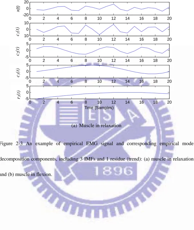
2-3 An example of empirical EMG signal and corresponding empirical mode decomposition components, including 3 IMFs and 1 residue (trend): (a) muscle in relaxation and (b) muscle in flexion. ... - 16 -
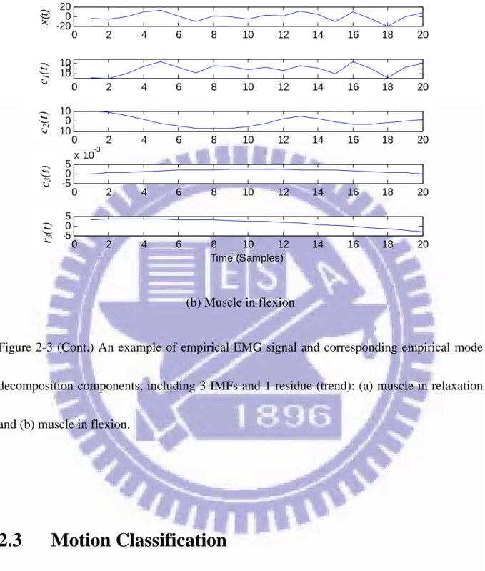
2-3 (Cont.) An example of empirical EMG signal and corresponding empirical mode decomposition components, including 3 IMFs and 1 residue (trend): (a) muscle in relaxation and (b) muscle in flexion... - 17 -
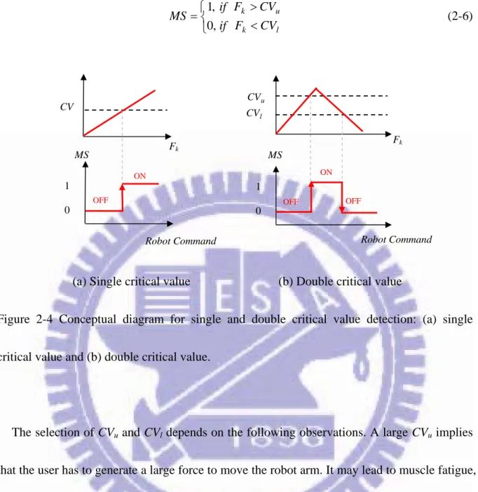
2-4 Conceptual diagram for single and double critical value detection: (a) single critical value and (b) double critical value. ... - 19 -
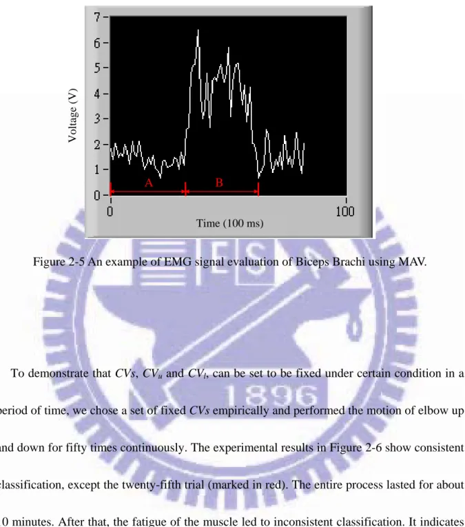
2-5 An example of EMG signal evaluation of Biceps Brachi using MAV. ... - 20 -
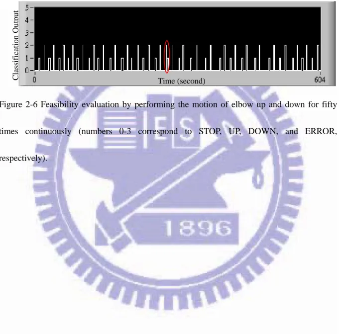
2-6 Feasibility evaluation by performing the motion of elbow up and down for fifty times continuously (numbers 0-3 correspond to STOP, UP, DOWN, and ERROR, respectively). ... - 21 -
3-1 Electrode locations: (a) Biceps Brachii and Pectoralis Major, and (b) Triceps Brachii and Teres Minor. ... - 23 -
3-2 Illustrations of classification outputs corresponding to the robot arm movements... - 24 -
3-3 System implementation of the proposed scheme. ... - 26 -
3-4 iWork ETH-256. ... - 27 -
3-5 National Instrument USB-6009 A/D data acquisition device. ... - 28 -
3-6 LabView Development System Console... - 28 -
3-9 Filtered EMG signals for subjects A-C. ... - 33 -
3-9 (Cont.) Filtered EMG signals for subjects A-C. ... - 34 -
3-10 EMG feature variations for subjects A-C... - 35 -
3-10 (Cont.) EMG feature variations for subjects A-C. ... - 36 -
3-11 Outputs from the classifier for subjects A-C... - 37 -
3-12 Fuzzy partitions of MAV, BZC, and CVu (CVl). ... - 39 -
3-13 Filtered EMG signals for subjects A-C. ... - 41 -
3-13 (Cont.) Filtered EMG signals for subjects A-C. ... - 42 -
3-14 EMG feature variations for subjects A-C... - 42 -
3-14 (Cont.) EMG feature variations for subjects A-C. ... - 43 -
3-15 Outputs from the classifier for subjects A-C... - 44 -
4-1 Conceptual diagram of the proposed ANFIS for CVu and CVl determination. ... - 48 -
4-2 Structure of the ANFIS for the proposed system. ... - 50 -
4-3 Bell-shaped membership functions for input variables... - 51 -
4-4 Results for experiment 1. ... - 53 -
4-4(Cont.) Results for experiment 1. ... - 54 -
4-5 Results for experiment 2. ... - 55 -
4-5 (Cont.) Results for experiment 2. ... - 56 -
4-5 (Cont.) Results for experiment 2. ... - 57 -
4-6 Results for experiment 3. ... - 58 -
Chapter 1
Introduction
Nowadays, the number of disabled and elderly is increasing. With a decreasing birthrate, the development of the human-assisting manipulators is imperative for them to alleviate the dependence and improve the quality of life. Teach box, joystick, and keyboard, are traditional devices used for manipulation. Currently, voice control also becomes an alternate [1]. Along with the development in the areas of sensing and measurement techniques, signal processing, and biomedical engineering, it is no longer a dream by using the physiological signals to serve as the control signal for the computer, home appliances, mechanical devices, etc.
EMG is a physiological signal generated from the exchange of ions across muscle fiber membranes during muscle contraction. Its amplitude ranges between 0~10 mV (peak to peak) or 0~1.5 mV (root mean square). Its frequency, varying according to the motion and individual, ranges between 0~500 Hz, with a distribution mainly around 50~150 Hz [2]. By applying the conductive elements or electrodes on the skin surface, or invasively within the muscle, EMG signal can thus be measured. As EMG implicates several important messages, such as the muscular force level and operator’s intention, it is very suitable to serve as the control signal, and also leads to a natural and intuitive manipulation. Researchers have devoted to the study of applying EMG for controlling human-assisting robots and
rehabilitation devices for the physically handicapped as well as the elderly to improve their life quality. Fukuda et al. [3] proposed teleoperating a human-assisting manipulator by using EMG signals. Artemiadis and Kyriakopoulos [4] proposed an EMG-based position and force control scheme for robot arm. Ferreira et al. [5] applied the EMG and EEG (electroencephalogram) for developing the interfaces for robot systems. Gao et al. [6] developed a robotic arm wrestling system based on EMG and artificial neural network. Gopura and Kiguchi [7] developed exoskeleton robots for assisting the motion of physically weak individuals based on EMG and fuzzy control. Ito et al. [8] presented prosthetic speed control by utilizing the relation of the proportion of muscular contraction level. Oppenheim et al. [9] proposed using EMG as an input device for the Nintendo Wii™ video game console. Huang et al. [10] proposed using the EMG signals combined with the pattern recognition technique to identify user locomotion modes. Aso et al. [11] presented using EMG to drive the electric car. And, Harada et al. [12] proposed using EMG to control robot finger.
Because EMG exhibits high nonlinearity and fuzziness [13-15], even for the same motion executed by the same person, different EMG measurements may be obtained under different circumstances. Among these researches, EMG signals were identified to be affected by noises, such as ECG (electrocardiogram) crosstalk, electromagnetic induction from power lines, and arm and cable movements. Meanwhile, muscle mutual interference, physiological condition (e.g., fatigue), skin impedance and temperature, etc., also contribute to the fuzziness of the
EMG signals, which are time-varying and highly nonlinear. These properties result in the difficulty in extracting proper EMG features for motion classification.
To extract and recognize the intended movement pattern from EMG, several methods have been proposed, in time domain, such as mean absolute value, variance, bias zero-crossing, Willison amplitude, autoregressive model [16-18], Euclidean distance and standard deviation [19], and hidden Markov model [20] , etc., and in frequency domain, such as Fourier transform [21] and wavelet analysis [22, 23]. However, those approaches in the time domain induce high computational complexity [17]. Meanwhile, EMG signals are nonlinear and non-stationary signals, especially for contraction levels higher than 50% of maximum voluntary contraction (MVC) [24]. But the data must be linear and strictly stationary for Fourier transform [25]. As for the wavelet analysis, a mother wavelet has to be defined a priori [26]. Unsuitable mother wavelet may lead to unsatisfactory results. Some researchers proposed using the learning approach, e.g., the neural network [6, 27, 28], and reported salient performance. But, the learning approach demands certain computational load and incurs some system complexity for the learning and training processes involved.
Alternatively, Hilbert-Huang transform (HHT) is a time-frequency method. Based on the local time scale of the data, it decomposes a signal into several intrinsic mode functions (IMFs) via empirical mode decomposition (EMD), and then calculates the instantaneous frequency of each IMF at any point in time via Hilbert transform. Hence, it can be used for
nonlinear and non-stationary data analysis. HHT has been broadly applied in numerous scientific disciplines and investigations, e.g., analysis on the bioelectricity signal, failure testing, and earthquake signal etc. [29]. Several researchers have applied HHT to EMG related studies. Xie and Wang. [24] and Peng et al. [30] adopted HHT to find the features of muscular fatigue. Ma and Luo [29] proposed using HHT and AR-model to extract the sEMG feature to recognize the hand-motions. Wang et al. [31] presented a feature extraction technique based on empirical mode decomposition to classify the walking activities from accelerometry data. Chen et al. [32] employed HHT to extract the frequency features of the stump to control transfemoral prosthesis. Zong and Chetouani [25] presented a feature extraction technique based on HHT for emotion recognition from physiological signals.
1.1 Motivation
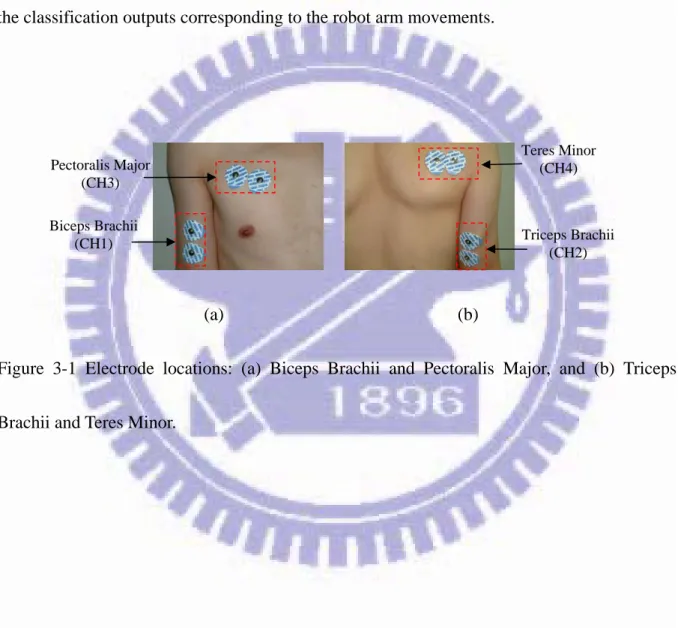
To develop an EMG based human-assisting manipulator needs to well consider the influence from the muscle type, strength of muscle contraction, fatigue level, strategy in performing the task, and others. Several EMG based human-assisting manipulators have been proposed, whose feature extraction and classification/recognition designs are summarized in Table 1-1. These manipulators require either complicated computation or tedious training and learning processes, as a result, the practicality is decreased. As the commercial prosthesis have no profound theory and complex mechanism, meanwhile, their operations are simple and easy,
we, therefore, propose a simple and effective system for governing robot arm motion via the upper limb EMG signal, whose feature extraction and classification designs are listed in Table 1-1 as well. With the assistance of the proposed system, the physically weak individual (disabled, injured or elderly) can do some important daily activities such as eating from spoon, drinking from cup and pouring from a bottle, etc. by themselves without needing assistance from others. In addition to the robot arm motion governing, the proposed method can further be used for governing the different fundamental applications, such as the devices with bidirectional commands (on/off, increment/decrement), prosthetic hand, TV and radio for instance.
Table 1-1 EMG based human-assisting manipulators
Human-assisting manipulators
EMG
Channel Feature Extraction
Classification/
Recognition Reference Robot finger 3 Fast Fourier
transform Neural network [12] Robot exoskeleton 8 MAV Neuro-fuzzy approach [14] Prosthetic hand 2 VAR, BZC, autoregressive model, and spectral estimation
Artificial neural
network [17] Transfemoral
prosthesis 5 Hilbert-Huang transform [32]
Robot arm 11
Integral of absolute value, zero corssing, VAR, Median frequency Switching regime decoding model, principal component analysis, [33]
Robot arm 4 Initial point
detection EMD
This dissertation
1.2 Contribution
The contribution of this dissertation is proposing an EMG-base robot control system to provide a natural and intuitive manipulation for governing robot arm motion. The presented initial point detection method [34, 35] discriminates the upper limb motion onset by detecting the instant when the magnitude of the extracted EMG feature reaches the upper critical value (CVu) and offset when that descends to the lower critical value (CVl) from onset state.
Consequently, the mapping between the upper limb EMG signals and the corresponding robot arm movements can be established very quickly. Meanwhile, due to the individual fuzziness, such as the muscular fatigue, skin impedance and temperature, and muscle mutual interference, etc., the tuning of the system parameters for the individual user is not that straightforward. As an effective means for tackling the system with uncertainties [36-38], thus the concept of the fuzzy system is employed, so that the tedious process encountered in the trial-and-error method can be avoided. Because neither complicated computation nor training and learning processes are needed, this method not only simplifies system complexity, but also increases the efficiency in motion governing. While the proposed system is shown to be effective for robot motion governing, it is not appropriate to serve as a classifier for more than 1-DOF (degree of freedom) limb motion, as limb motion of multi-DOF induces larger muscle mutual interference. To tackle this, the EMD is applied to decompose the EMG signals into several IMFs. Each IMF represents different physical characteristic, so that the major muscular movements can be recognized. To reduce the computational load in EMD, a sixth-order band-pass Butterworth filter and a dedicated data sampling window are employed. Meanwhile, for multi-DOF upper limb motion, the fuzzy system adopted for 1-DOF motion is not efficient enough for the tuning of the CVu and CVl for each individual user. For its
excellence on adaptation, the adaptive neuro-fuzzy inference system (ANFIS) [39-42] is employed to realize the fuzzy system. The ANFIS has been successfully implemented in
biomedical engineering for classification [43-46] and robot control [47, 48]. A series of experiments are performed to demonstrate the effectiveness and feasibility of the proposed system in governing a 3-DOF robot arm motion via four surface EMG electrodes placed on Biceps Brachii, Triceps Brachii, Pectoralis Major, and Teres Minor. While the results are shown to be effective for robot motion governing, the limitation of this system is that fixed critical values (CVs) are suitable for robot motion governing for about 5 ~ 10 minutes, depending on the complexity of the motion. After that, the fatigue of the muscle led to inconsistent classification. We suggest the proposed system not to be used when the subject feels fatigued. Meanwhile, at this stage of the research, this EMG-based robot control system will be based on human upper-limb motion, as a starting point.
1.3 Organization
In Chapter 2, the proposed EMG-based upper-limb robot control system is described, including the modules for EMG signal measurement and processing, feature extraction, and motion classification. Chapter 3 describes the experimental setup, design and experimental results for 1-DOF robot arm movement control. Those for 3-DOF robot arm movement are presented in Chapter 4. Finally, conclusions along with some future works are given in Chapter 5.
Chapter 2
Proposed EMG-Based Upper-Limb Robot Control
System
To provide a simple and effective approach for governing robot arm motion in real time via EMG signals, we propose using upper limb EMG signals to develop an EMG-based robot motion governing system as the movements involved in it are not complicated. Figure 2-1 shows the system diagram of the proposed EMG-based upper-limb robot control system, which consists of three main modules: signal measurement and processing, feature extraction, and motion classification. The signal measurement and processing module measures the raw EMG signals of the upper limb and also filters out the noises. The filtered EMG signals are then sent to the feature extraction module to derive their features. With these features, the motion classification module determines the corresponding arm movements and generates the commands to drive the human-assisting robot. From the resultant robot motion, the operator evaluates the performance and determines the next movement. These three modules are described below.
Features Upper-limb motion Signal Measurement & Processing Motion command Robot motion Feature Extraction Motion Classification Human- Assisting Robot Operator Filtered EMG
Figure 2-1 Proposed EMG-based upper-limb robot control system
2.1 Signal Measurement and Processing
For EMG signal measurement, the locations and areas of those muscles involved during upper limb movement are needed to consider. The measurement also depends on the regions where the electrodes are placed. To obtain more precise EMG signals, the electrodes need to be placed on the midline of the muscle belly, with the electrodes aligned parallel to the muscle fibers. The recommended inter-electrode distance (from one differential electrode to the other) is about 1~2 cm [2, 49]. Several types of noises may affect the measurement of the EMG signals, such as ECG crosstalk, electromagnetic induction from power lines, and arm and cable movements. The ECG crosstalk can be suppressed by measuring signals from those
muscles away from the heart. The frequency of the electromagnetic noise is around 60 Hz. While a notch filter at that frequency can be an option, it should be avoided, because EMG has large signal contributions at these and neighboring frequencies. We thus let the proposed approach tackle its influence as the disturbance. Meanwhile, the frequency distribution for the arm and cable movements is around 0 to 20 Hz, which can be tackled using a high-pass filter.
2.2
Feature Extraction
To extract and recognize the intended movement pattern from EMG, several methods have been proposed, in time domain, such as mean absolute value (MAV), variance (VAR), bias zero-crossing (BZC), Willison amplitude (WAMP) [16,17], autoregressive model, Euclidean distance and standard deviation, and hidden Markov model , etc., and in frequency domain, such as Fourier transform and wavelet analysis. Among them, MAV, VAR, BZC and WAMP are four famous feature extraction indices for EMG signal. The formulae for these indices are listed in Table 2-1, in which kdenotes the kth sampling data in the window for computing
the feature and N is the window length. MAV is taken as the estimation for signal power and VAR that for power density. Both MAV and VAR are frequently used to estimate the contraction level of the muscle. BZC, which includes a bias value for dealing with noise
interference, counts the zero-crossing, i.e., the number of times the signal passes the zero value. And, WAMP is used to count the number of times the signal amplitude exceeds a predefined threshold, indicating the contraction level of the muscle. The proposed system adopts MAV as the feature extraction index, because we intend to evaluate the contraction level of the muscle. Meanwhile, VAR can also be an alternative.
Table 2-1 Feature extraction name and formula
Name Formula MAV 1 1 N k k MAV X N
VAR 2 1 1 1 N k k VAR X N
BZC 1 1 sgn ( 0.4) ( 0.4) 1 , if 0 sgn( ) 0 , others N k k k BZC X X x x
WAMP 1 1 ( ) 1 , if ( ) 0 , if otherwise N k k k WAMP f X X ; x threshold f x
However, the aforementioned methods are not appropriate to serve as a classifier for more than one-DOF upper limb motion as it has larger muscle mutual interference. Alternatively, the EMD method is one of solutions as it decomposes the EMG signals into several IMFs. Each IMF represents different physical characteristic and strength, so that the major muscular movement can be recognized. The following is an introduction of the EMD process.
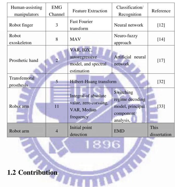
Figure 2-2 shows the flow chart of the EMD process, which deconstructs the complete signal into a set of IMFs in eight steps (with Steps 1 to 5 for the sifting process) [32, 50]:
Step 1: Identify the local maxima in the filtered EMG data x
t by interpolating between the maxima and connect them via a cubic spline curve to obtain the upper envelope U
t .Step 2: Apply the same actions in Step 1 to identify the local minima and obtain the lower envelope L
t .Step 3: Compute the mean value of the upper and lower envelope m1
t :
2 1 t L t U t m (2-1)Step 4: Subtract the running mean value m1
t from the original data to obtain the first component :
t x
t h1 h1
t x t m1
t (2-2)Step 5: Iterate Steps 1-4 on h1
t for k times until the resulting component h1k
ter of local (h1 k1
t m1k
t ) satisfies two conditions: (a) the difference between the numbextremes and that of zero-crossings is zero or one and (b) the running mean value is zero.
Step 6: Designate if meets the two requirements mentioned above.
Step 7: Subtract the first IMF 1 from the original data to obtain the residual 1
t h
t c1 1k h1k
t c r
t :
t xt c
t r1 1 (2-3)Step 8: Treat r1
t as the new data and repeat Steps 1-7 on to obtain all the subsequent i.e.,
t r1
t r1
t c2
tr2 ,, rn
t rn1
t cn
t until the final residual rn
tmeets the predefined stopping criteria as a monotonic function, considered as the trend.
Based on the procedure above, the original data x
t can be exactly reconstructed by a linear superposition:
n i n i t r t c t x 1 (2-4)where n is the number of IMFs.
No Filtered EMG Signals Shifting Process Intrinsic Mode Functions Trend or Constant Yes Stop Empirical Mode Decomposition
x(t) hi(t) ri(t)
Figure 2-2 Flow chart for empirical mode decomposition
The number of IMFs depends on the characteristic of data. A complex data can be decomposed into more IMFs, which increases the computational load in EMD. As EMG signals are complex physiological signals, high data sampling window results in the fact that the mapping between the upper limb EMG signals and the corresponding robot arm
movements can not be established in the expected time. After several experiments, we found combining a sixth-order band-pass Butterworth filter with a window with 20 samples per second can reduce the computational load, meanwhile, the sampled data can be decomposed into three IMFs within one second. Among which, the 2nd IMF is on behalf of the limb movement. Figure 2-3 shows an example of the EMD process on the dedicated EMG data sampling window when muscle relaxes and flexes. Each of them includes the empirical EMG signal x(t), three IMFs (c1(t), c2(t), c3(t)), and residue (r3(t)). The summation of IMFs and
residue exactly equals to the empirical EMG signal. By judging from Figures 2-3(a) and (b), c1(t) shall be the background noise induced by skin impedance and temperature, cable
movement, etc., since its magnitude does not vary with arm movement evidently. In contrast, those of c2(t) and c3(t) are varied. As the strength of the magnitude of c2(t) increases when
0 2 4 6 8 10 12 14 16 18 20 -20 0 20 x( t) 0 2 4 6 8 10 12 14 16 18 20 -10 0 10 c1 (t ) c1 (t) 5 0 2 4 6 8 10 12 14 16 18 20 -5 0 c2 (t ) 0 2 4 6 8 10 12 14 16 18 20 -5 0 5 c3 (t ) c2 (t) c3 (t) 5 0 2 4 6 8 10 12 14 16 18 20 -5 0 Re s id u e Time (Samples) r (t) 3
(a) Muscle in relaxation
Figure 2-3 An example of empirical EMG signal and corresponding empirical mode decomposition components, including 3 IMFs and 1 residue (trend): (a) muscle in relaxation and (b) muscle in flexion.
0 2 4 6 8 10 12 14 16 18 20 -200 20 x( t) 0 2 4 6 8 10 12 14 16 18 20 -10100 c1 (t ) 0 2 4 6 8 10 12 14 16 18 20 -100 10 c2 (t ) 0 2 4 6 8 10 12 14 16 18 20 -50 5x 10 -3 c3 (t ) c1 (t) c2 (t) c3 (t) 0 2 4 6 8 10 12 14 16 18 20 -50 5 Re s id u e Time (Samples) r (t) 3 (b) Muscle in flexion
Figure 2-3 (Cont.) An example of empirical EMG signal and corresponding empirical mode decomposition components, including 3 IMFs and 1 residue (trend): (a) muscle in relaxation and (b) muscle in flexion.
2.3
Motion Classification
2.3.1 Initial Point Detection
Because the movements involved in the proposed system are not complicated, an initial point detection method is proposed to deduce the motion intention from the EMG signal. The
reason for the naming is because this method determines the onset of the upper limb motion via detecting the instant when the magnitude of the extracted EMG feature reaches the critical values. Due to its simplicity, real-time motion governing can be achieved. In the proposed classifier design, we start with the single critical value detection, in which the state of the muscle MS is determined by checking if the initial value for the feature exceeds a predefined critical value: , 0 , 1 MS if otherwise CV Fk (2-5)
where Fk stands for the th feature and CV the critical value. An active MS corresponds to an
``ON’’ robot command and an inactive one for that of ``OFF’’, as illustrated in Figure 2-4(a). Figure 2-5 shows an example, in which MAV is used to evaluate the EMG signal of Biceps Brachii. In Figure 2-5, section A indicates the muscle state during relaxation, and section B that during flexion, both of which exhibit some fluctuations. We thus propose a concept of double critical value detection, as illustrated in Figure 2-4(b). In Figure 2-4(b), the state of the muscle MS is determined to be active when the initial value for the feature Fk is larger than
the upper critical value CVu, and MS inactive when Fk is smaller than the lower critical value CVl:
(2-6) , 0 , 1 MS if if l k u k CV F CV F
(a) Single critical value (b) Double critical value
Figure 2-4 Conceptual diagram for single and double critical value detection: (a) single critical value and (b) double critical value.
The selection of CVu and CVl depends on the following observations. A large CVu implies
that the user has to generate a large force to move the robot arm. It may lead to muscle fatigue, in addition to the increase of the crosstalk between muscles. Contrarily, a small CVu results in
low tolerance against the noise. Meanwhile, a large CVl may make the robot arm stop its
movement earlier than that of the user, while a small CVl leads to the opposite. The
approaches of the trial-and-error method and fuzzy system can be utilized for determining
CVu and CVl. MS OFF Robot Command ON Fk CV 1 0 l CV Fk OFF OFF CVu MS ON 1 0 Robot Command
Voltage (V)
A B
Time (100 ms)
Figure 2-5 An example of EMG signal evaluation of Biceps Brachi using MAV.
To demonstrate that CVs, CVu and CVl, can be set to be fixed under certain condition in a
period of time, we chose a set of fixed CVs empirically and performed the motion of elbow up and down for fifty times continuously. The experimental results in Figure 2-6 show consistent classification, except the twenty-fifth trial (marked in red). The entire process lasted for about 10 minutes. After that, the fatigue of the muscle led to inconsistent classification. It indicates that fixed CVs are appropriate for the proposed system to govern robot motion for a certain period of time, but should not be used when the subject felt fatigued.
Several factors influence the realization of the classifier, including feature selection, number of samples for feature extraction, and choice of the CVs. It is suggested to use
features with smooth waveforms. A larger number of samples may be helpful for feature extraction, at the expense of efficiency and delay.
Classifi cation Out p u t Time (second)
Figure 2-6 Feasibility evaluation by performing the motion of elbow up and down for fifty times continuously (numbers 0-3 correspond to STOP, UP, DOWN, and ERROR, respectively).
Chapter 3
Experimental Design
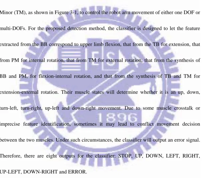
The proposed EMG-based upper-limb robot control system is using four sets of electrodes placed on Biceps Brachii (BB), Triceps Brachii (TB), Pectoralis Major (PM), and Teres Minor (TM), as shown in Figure 3-1, to control the robot arm movement of either one DOF or multi-DOFs. For the proposed detection method, the classifier is designed to let the feature extracted from the BB correspond to upper limb flexion, that from the TB for extension, that from PM for internal rotation, that from TM for external rotation, that from the synthesis of BB and PM, for flexion-internal rotation, and that from the synthesis of TB and TM for extension-external rotation. Their muscle states will determine whether it is an up, down, turn-left, turn-right, up-left and down-right movement. Due to some muscle crosstalk or imprecise feature identification, sometimes it may lead to conflict movement decision between the two muscles. Under such circumstances, the classifier will output an error signal. Therefore, there are eight outputs for the classifier: STOP, UP, DOWN, LEFT, RIGHT, UP-LEFT, DOWN-RIGHT and ERROR.
Table 3-1 summarizes the mapping from EMG to robot movement. When EMG signals from all channels (CH1~4) are determined to be OFF, the classifier outputs 0 as relaxation; ON for CH1 and OFF for the others, outputs 1 as flexion; ON for CH2 and OFF for the others, outputs 2 as extension; ON for CH3 and OFF for the others, outputs 3 as internal rotation; ON
for CH4 and OFF for the others, outputs 4 as external rotation; simultaneously ON for CH1 & CH3 and OFF for the others, outputs 5 as flexion plus internal rotation; simultaneously ON for CH2 & CH4 and OFF for the others, outputs 6 as extension plus external rotation; and simultaneously ON for undefined channels, outputs 7 as error detection. Figure 3-2 illustrates the classification outputs corresponding to the robot arm movements.
Biceps Brachii (CH1) Teres Minor (CH4) Triceps Brachii (CH2) Pectoralis Major (CH3) (a) (b)
Figure 3-1 Electrode locations: (a) Biceps Brachii and Pectoralis Major, and (b) Triceps Brachii and Teres Minor.
Table 3-1 Mapping from EMG to robot movement EMG BB (CH1) TB (CH2) PM (CH3) TM (CH4)
Upper Limb Status Classifier
Output Robot Arm OFF OFF OFF OFF Relaxation 0 STOP
ON OFF OFF OFF Flexion 1 J2 axis UP
OFF ON OFF OFF Extension 2 J2 axis DOWN OFF OFF
ON OFF Internal Rotation 3 J1 axis TURN LEFT OFF OFF
OFF ON External Rotation 4 J1 axis TURN RIGHT
ON OFF ON OFF Flexion-Internal Rotation 5 J5 axis UP
OFF ON OFF ON Extension-External Rotation 6 J5 axis DOWN
The others Error 7 STOP
Classifier Output 0 1 2 3 4 5 6
3.1 Experimental Setup
A series of experiments were performed to evaluate the performance of the proposed system. Figure 3-3 shows the implementation of the proposed system for experiments. In Figure 3-3, the measured EMG signals are first amplified using the ETH-256 physiological signal amplifier (manufactured by iWorx Systems, USA, the specifications are listed in Table 3-2 and the hardware is shown in Figure 3-4), and the amplified analog signals (voltages) then transformed into digital signals via National Instrument USB-6009 A/D data acquisition device (the specifications are listed in Table 3-3 and the hardware is shown in Figure 3-5) with 1KS/s sampling rate. The digital signals are further forwarded to the LabVIEW development system, as Figure 3-6 shown, which includes a sixth-order band-pass Butterworth filter with the cut-off frequencies at 20 and 400 Hz, respectively, a 10-sampling-data-window feature extractor, and a motion classifier. Via the processing, robot motion commands can be determined, and then sent to a 6-DOF Mitsubishi RV-2A robot manipulator for execution (the specifications are listed in Table 3-4, and the axis definition is shown in Figure 3-7, only J1, J2 and J5 axes manipulated). The experimental setup is shown in Figure 3-8.
The effectiveness of the proposed scheme is demonstrated via the following two experiments: (1) 1-DOF robot arm movement governing and (2) multi-DOF robot arm
those for the later in Chapter 4 due to its complexity.
Figure 3-3 System implementation of the proposed scheme.
Table 3-2 iWork ETH-256 specifications Number of Channel 2
Operation Modes Bridge/Biopotential (ECG, EMG, EEG) Gain 1, 5, 10, 100, 500, 1K, 5K Filters High Pass (Hz): DC, 0.03, 0.3, 3
Low Pass (Hz): 5, 50, 150, 2K, 10K Input Impedance 10 G
Output Impedance 100 G Input Connector DIN & BNC Output Connector BNC Offset Range -5 ~ +5 V Common Mode Rejection 85db@200Hz
EMG signal Analog signal Digital signal EMG Amplifier Data Acquisition Device Motion command Butterworth Filter Feature Extractor Robot motion Motion Classifier LabView Development System
Figure 3-4 iWork ETH-256.
Table 3-3 National Instrument USB-6009 A/D data acquisition device specifications
Analog Input Number of channel: 8 Resolution: 14 bit Sampling rate: 48 KS/s Analog Output Number of channel: 2 Resolution: 12 bit Sampling rate: 150 S/s Digital I/O Number of channel: 12
Figure 3-5 National Instrument USB-6009 A/D data acquisition device.
Table 3-4 Mitsubishi RV-2A robot arm specifications Degrees of freedom 6
Maximum load capacity
2 Kg (rating)
Maximum reach radius 621 mm Pose repeatability 0.04 mm Weight 37 Kg Shoulder shift 100 mm Upper arm 250 mm Fore arm 250 mm Arm length Elbow shift 130 mm Wrist length 85 mm J1 axis 320° (-160 to +160) J2 axis 180° (-45 to +135) J3 axis 120° (+50 to +170) J4 axis 320° (-160 to +160) J5 axis 240° (-120 to +120) Operating range J6 axis 400° (-200 to +200)
Figure 3-7 Mitsubishi RV-2A robot arm axis definition. RV-2A LabVIEW Develop System ETH-256 USB-6009 A/D
3.2
One-DOF Robot Arm Movement Control
Two sets of electrodes placed on the Biceps Brachii, marked as CH1, and the Triceps Brachii, marked CH2, respectively, shown in Figure 3-1, are used to govern the motion of RV-2A. First things first, the setting of CVu and CVl has to be determined for the invited subjects. In
the first set of experiments, we used the empirical method to determine CVu and CVl for the
three invited male subjects, with their physical data listed in Table 3-5 and derived CVu and CVl in Table 3-6. Their determination is customized for each individual subject through an extensive trial-and-error procedure according to the effectiveness on classification. The subject was asked to contract/extend his upper limb to move robot arm, J2 axis, from 0 to 90 degrees, 90 to 0 degrees, 0 to 45 degrees, 45 to 90 degrees, 90 to 45 degrees, and 45 to 0 degrees. The moving speed of the robot arm is 6 deg./sec. We define the successful discrimination rate (SDR) as the times that the robot arm successfully follows the motion of the subject out of the total number of classification:
% 100 tion classifica of number Total following motion successful of Number SDR (3-1)
Table 3-5 Physical data of the three male subjects
Subject Height (cm) Weight (kg)
Muscle for electrode
A 174 70 Ordinary
B 166 60 Slender C 164 82 Fat
Table 3-6 Critical values via the empirical method
Biceps Brachi Triceps Brachi Subject
CVu CVl CVu CVl
A 4.5 2.2 4 2.5 B 3.2 2.2 4.5 3 C 5 2.8 5 3.3
The experimental results are shown in Figures 3-9 to 3-11. Figure 3-9 shows the EMG signals after band-pass filtering for subjects A-C, in which larger amplitudes indicate larger forces during the movements of the flexor/extensor. Figure 3-10 shows the variations of MAV features corresponding to the filtered EMG signals in Figure 3-9. Based on these features, the classifier determines the corresponding upper limb movements, while more evident feature
variations lead to better discrimination. Figure 3-11 shows the outputs from the classifier, where numbers 0-3 in the vertical coordinate denote STOP, UP, DOWN, and ERROR respectively, and I-VI the stages of 0-90, 90-0, 0-45, 45-90, 90-45, and 45-0.
Subject C reported that he felt a little bit fatigued. It might be due to higher CVu and CVl
demanded him to make more effort for movement. The SDR for the subjects is 95.5%, 97%, and 95.5%, respectively, indicating quite successful motion following.
0 200 400 600 800 1000 1200 1400 1600 1800 2000 -20 -10 0 10 20
Filtered Biceps Brachii EMG
Sample V ol tage ( V ) 0 200 400 600 800 1000 1200 1400 1600 1800 2000 -20 -10 0 10 20
Filtered Triceps Brachii EMG
Sample V ol tage ( V ) (a) Subject A
0 200 400 600 800 1000 1200 -20 -10 0 10 20
Filtered Biceps Brachii EMG
Sample V ol tage ( V ) 0 200 400 600 800 1000 1200 -20 -10 0 10 20
Filtered Triceps Brachii EMG
Sample V ol tage ( V ) (b) Subject B 0 200 400 600 800 1000 1200 1400 1600 1800 -20 -10 0 10 20
Filtered Biceps Brachii EMG
Sample V ol tage ( V ) 0 200 400 600 800 1000 1200 1400 1600 1800 -20 -10 0 10 20
Filtered Triceps Brachii EMG
Sample V ol tage ( V ) (c) Subject C
0 20 40 60 80 100 120 140 160 180 200 0
2 4 6
Biceps Brachii MAV
Time (S) V ol tage ( V ) 0 20 40 60 80 100 120 140 160 180 200 0 2 4 6 8
Triceps Brachii MAV
Time (S) V ol tage ( V ) (a) Subject A 0 20 40 60 80 100 120 0 2 4 6
Biceps Brachii MAV
Time (S) V ol tage ( V ) 0 20 40 60 80 100 120 0 2 4 6 8
Triceps Brachii MAV
Time (S) V ol tage ( V ) (b) Subject B
0 20 40 60 80 100 120 140 160 180 0 2 4 6 8
Biceps Brachii MAV
Time (S) V ol tage ( V ) 0 20 40 60 80 100 120 140 160 180 0 2 4 6 8
Triceps Brachii MAV
Time (S) V ol tage ( V ) (c) Subject C
(a) Subject A (b) Subject B I II III IV V VI I II III IV V VI I II III IV V VI (c) Subject C
Due to the individual fuzziness, the tuning of the system parameters for the individual user is not that straightforward. Thus the concept of the fuzzy system [35, 51, 52] is employed for
CVu and CVl determination, so that the tedious process encountered in the trial-and-error
method can be avoided. MAV (signal power) and BZC (zero crossing) were chose as the input variables of the fuzzifier, as each of them provides the time- and frequency-domain estimation, respectively. Figure 3-12 shows the fuzzy sets used for MAV, BZC, and CVu (CVl),
where W, M, and S stand for weak, middle, and strong, L, M, and H for low, middle, and high, , , and () the strength of MAV, BZC, and CVu (CVl), respectively, and A, B, and C (D)
the membership function for MAV, BZC and CVu (CVl). With them, the fuzzifier transforms
the extracted features into the linguistic values. The fuzzy rules, listed in Table 3-7, are obtained from the empirical knowledge acquired via extensive experiments. The values of and are empirically set to be 1/3 of the MAV and BZC, respectively, and and are 2 and 1.4 times of . The fuzzy inference engine determines the jth firing strength j of the jth fuzzy
rule via Eq.(3-2):
j
j B
A
j
(3-2)
And, the defuzzifier utilizes the center of gravity (COG) method to map the inferred fuzzy action into a nonfuzzy value of CVu (CVl):
n j j n j j j l u z CV CV 1 1 ) ( (3-3)where n is the number of fuzzy rule and zj the strength of CVu (CVl) at the jth fuzzy rule. CVu (CVl) L M H 1 0 () (2) 2 (3) 3 C(D) W M S 1 0 2 3 A B 1 0 2 3 W M S MAV BZC (a) MAV (b) BZC (c) CVu (CVl)
Figure 3-12 Fuzzy partitions of MAV, BZC, and CVu (CVl).
Table 3-7 Fuzzy rule base BZC CVu,(CVl) W M S W L M M M M M H MAV S H H H
In the second set of experiments, the fuzzy system is used to determine CVs for each individual user, listed in Table 3-8, and asked the subjects to perform the same movements as
those they did in the first set of experiments. The experimental results are shown in Figures 3-13 to 3-15. Figure 3-13 shows the filtered EMG signals, Figure 3-14 variations of the MAV features, and Figure 3-15 outputs from the classifier. The SDR for the subjects is 95.5%, 97%, and 97%, respectively, also indicating quite successful motion following. From Tables 3-6 and 3-8, different set of CVs were derived by the empirical method and fuzzy system, while both of them led to successful motion governing. Meanwhile, the fuzzy system may be with better potential when dealing with more complex movement, as it possesses the ability of automatic parameter tuning.
Table 3-8 Critical values via the fuzzy system Biceps Brachi Triceps Brachi Subject
CVu CVl CVu CVl
A 4.09 2.86 4.25 2.98 B 4.99 3.49 4.34 3.04 C 4.36 1.96 4.95 2.23
0 200 400 600 800 1000 1200 1400 1600 1800 2000 -20 -10 0 10 20
Filtered Biceps Brachii EMG
Sample V ol tage ( V ) 0 200 400 600 800 1000 1200 1400 1600 1800 2000 -20 -10 0 10 20
Filtered Triceps Brachii EMG
Sample V ol tage ( V ) (a) Subject A 0 200 400 600 800 1000 1200 1400 1600 1800 -20 -10 0 10 20
Filtered Biceps Brachii EMG
Sample V ol tage ( V ) 0 200 400 600 800 1000 1200 1400 1600 1800 -20 -10 0 10 20
Filtered Triceps Brachii EMG
Sample V ol tage ( V ) (b) Subject B
0 200 400 600 800 1000 1200 1400 1600 1800 -20 -10 0 10 20
Filtered Biceps Brachii EMG
Sample V ol tage ( V ) 0 200 400 600 800 1000 1200 1400 1600 1800 -20 -10 0 10 20
Filtered Triceps Brachii EMG
Sample V ol tage ( V ) (c) Subject C
Figure 3-13 (Cont.) Filtered EMG signals for subjects A-C.
0 20 40 60 80 100 120 140 160 180 200 0 2 4 6 8
Biceps Brachii MAV
Time (S) V ol tage ( V ) 0 20 40 60 80 100 120 140 160 180 200 0 2 4 6 8
Triceps Brachii MAV
Time (S) V ol tage ( V ) (a) Subject A
0 20 40 60 80 100 120 140 160 180 0 2 4 6 8
Biceps Brachii MAV
Time (S) V ol tage ( V ) 0 20 40 60 80 100 120 140 160 180 0 2 4 6
Triceps Brachii MAV
Time (S) V ol tage ( V ) (b) Subject B 0 20 40 60 80 100 120 140 160 180 0 2 4 6 8
Biceps Brachii MAV
Time (S) V ol tage ( V ) 0 20 40 60 80 100 120 140 160 180 0 2 4 6 8
Triceps Brachii MAV
Time (S) V ol tage ( V ) (c) Subject C
(a) Subject A (b) Subject B I II III IV V VI I II III IV V VI I II III IV V VI (c) Subject C
Chapter 4
Multi-DOF Robot Arm Movement Control
While the proposed system is shown to be effective for 1-DOF robot motion governing, it is not appropriate to serve as a classifier for more than 1-DOF upper limb motion as it has larger muscle mutual interference. To tackle this, the EMD method is applied in feature extraction design. To reduce the computational load in EMD, a sixth-order band-pass Butterworth filter and a window with 20 samples per second are employed. The muscle state was determined by the root mean square (RMS) of the 2nd IMF, c2(t), expressed as:
Fk = RMS(c2(t)), 0 t 20 (4-1)
Meanwhile, for multi-DOF upper limb motion, the fuzzy system adopted for 1-DOF motion is not efficient enough for the tuning of the critical valuesfor each individual user. For its excellence on adaptation, the ANFIS is employed to realize the fuzzy system.
4.1 Adaptive Neuro-Fuzzy Inference System
Figure 4-1 shows the conceptual diagram of the proposed ANFIS for CVu and CVl
Brachii (TB), Pectoralis Major (PM), and Teres Minor (TM) into linguistic variables. One degree of Sugeno-type inference system is employed to depict the fuzzy rule in fuzzy inference engine. The fuzzy rules are formulated as
Ri: IF BB is Ai and TB is Bi and PM is Ci and TM is Di THEN CVu (CVl)= pi BB + qiTB + ri PM +si TM, i{1,2, …,54} (4-2)
where BB, TB, PM, and TM are the input variables, A, B, C, D = {W, M, S} linguistic variables, CVu (CVl) the output variable, and
pi qi ri si
the consequent parameter set.Defuzzifier transforms the fuzzy results of the inference into a real CVu (CVl) using weighted
averaged method. ANFIS uses the least-squares method to identify the consequent parameter set and the backpropagation gradient descent method to set the premise parameters of the membership function to emulate the given training data set, listed in Table 4-1, where INa, INb,
INc, INd stand for the EMG signals of BB, TB, PM and TM, respectively, OUT for CVu, W, M,
S, VL, L, H and VH for weak, middle, strong, very low, low, high and very high. By extensive experiments, the values of the W, M, S in INa~INd are empirically set to be 1/3, 2/3,
1 of INa~INd, respectively, and those of VL, L, M, H and VH in OUT are 1/3, 2/3, 1, 4/3, 5/3
of INa~INd; CVl is set to be 0.7 times of CVu. By considering the conditions, such as skin
impedance and temperature, etc. are different from those of the training, the aforementioned values can be divided by a compensating parameter, , ranging from 0.8 to 1.3. The
Step 1: Set the compensating parameter, , to be 0.8 in the proposed ANFIS to obtain the first set of CVu and CVl.
Step 2: Ask the operator to perform the motion of flexion, extension, internal rotation, and external rotation two times consecutively.
Step 3: If the SDR is lower than 80%, add 0.1 to and iterate Steps 2-3 until the SDR is equal
to or more than 80%.
The proposed ANFIS consists of five layers as shown in Figure 4-2. Layer 1 is the input layer. Each node in this layer represents an input variable of the model with the membership function: ) ( 1 BB O i A i , , , , ( ) (4-3) 1 3 TB O i B i ( ) 1 6 PM O i C i ( ) 1 9 TM O i D i i1,2,3
The bell-shaped membership function is employed, shown in Figure 4-3, and expressed as
bi i i Ai a c BB BB 2 / 1 1 ) ( , i1,2,3 (4-4)
bi i i Bi a c TB TB 2 / 1 1 ) ( , i1,2,3 (4-5)
bi i i Ci a c PM PM 2 / 1 1 ) ( , i1,2,3 (4-6)
bi i i Di a c TM TM 2 / 1 1 ) ( , i1,2,3 (4-7)where represent the premise parameter set. Layer 2 is the inference layer. Each node in th ultiplied by the input signal to become :
(4-8)
ai bi ci
is layer is m wi ) ( ) ( ) ( ) ( 2 TM PM TB BB w Oi i Ai Bi Ci Di , 54i1,2, ,i
w stands for the firing strength of the rule. Layer 3 is the normalization layer that normalizes
the firing strength by calculating the ratio of ith firing strength to their sum:
54 1 3 j j i i i w w w O , i1,2,,54 (4-9)Layer 4 is the output layer. Each node multiplies the normalized firing strength by the consequent function to generate the qualified consequent of each rule. The output of the node is computed as
p BB qTB rPM sTM
w CV CV w Oi4 i u( l)i i i i i i , i1,2, ,54 (4-10) Layer 5 is the defuzzification layer, which computes the weighted average of the output signals from the output layer:
54 1 54 1 54 1 5 ( ) ) ( i i i i i u l i i l u i i w CV CV w CV CV w O (4-11) Fuzzy Inference Engine Fuzzy Rule ANFIS BicepsBrachii Fuzzifier Defuzzifier Training Data Fuzzy System Triceps Brachii Teres Minor Pectoralis Major CVl,BB,TB,PM,TM (CVu,BB,TB,PM,TM)Table 4-1 Training data set Set No. INa INb INc INd OUT Set No. INa INb INc INd OUT 1 W W W W VL 28 M W W W L 2 W W W M VL 29 M W W M L 3 W W W S L 30 M W W S M 4 W W M W VL 31 M W M W L 5 W W M M L 32 M W M M M 6 W W M S L 33 M W M S M 7 W W S W VL 34 M W S W L 8 W W S M L 35 M W S M M 9 W W S S L 36 M W S S M 10 W M W W L 37 M M W W M 11 W M W M L 38 M M W M M 12 W M W S L 39 M M W S M 13 W M M W M 40 M M M W H 14 W M M M M 41 M M M M H 15 W M M S M 42 M M M S H 16 W M S W M 43 M M S W H 17 W M S M M 44 M M S M H 18 W M S S M 45 M M S S H 19 W S W W H 46 M S W W VH 20 W S W M H 47 M S W M VH 21 W S W S H 48 M S W S VH 22 W S M W H 49 M S M W VH 23 W S M M H 50 M S M M VH 24 W S M S H 51 M S M S VH 25 W S S W VH 52 M S S W VH 26 W S S M VH 53 M S S M VH 27 W S S S VH 54 M S S S VH
Figure 4-2 Structure of the ANFIS for the proposed system. A1 A2 B1 B2 A3 B3 N N N N N N BB TB
Layer1 Layer2 Layer3 Layer4 Layer5
) ( l u CV CV 1 w w1 CVu1 (CVl1) C1 C2 D1 D2 C3 D3 TM PM 2 w CVu2 (CVl2) 3 w CVu3 (CVl3 ) 4 w CVu4 (CVl4 ) 5 w CVu5 (CVl5 ) 6 w CVu6 (CVl6) N N N N N N 49 w CVu49 (CVl49) 50 w CVu50 (CVl50) 51 w CVu51 (CVl51) 52 w CVu52 (CVl52) 53 w CVu53 (CVl53 ) 54 w CVu54 (CVl54)
) ( 54 54 54CVu CVl w ) ( 1 1 1CVu CVl w 8 w 18 w 28 w 38 w 48 w 54 w0.35 0.4 0.45 0.5 0.55 0.6 0.65 0.7 0 0.2 0.4 0.6 0.8 1 BB & PM W M S 0.4 0.5 0.6 0.7 0.8 0.9 1 0 0.2 0.4 0.6 0.8 1 TB & TM W M S )
Figure 4-3 Bell-shaped membership functions for input variables.
4.2 Experimental Results
The effectiveness of the proposed scheme for governing multi-DOF robot arm movement is demonstrated via asking two male and two female subjects (with their physical data listed in Table 4-2) to perform the following three experiments: (1) the motion of flexion, extension, internal rotation, and external rotation for four times consecutively, (2) the motion of flexion plus internal rotation, and extension plus external rotation for three times consecutively, and (3) the motion of elbow up, down, internal rotation, external rotation, flexion plus internal rotation, and extension plus external rotation for two times consecutively. Experiment 1 is
limb motions, experiment 2 to check the capability of the proposed system for recognizing the motion with larger muscle mutual interference, and experiment 3 to evaluate the operation duration of the proposed system.
Table 4-2 Physical data of the four subjects
Subject Height (cm) Weight (kg) Gender Muscle for electrode A 166 60 Male Slender B 164 82 Male Fat C 155 52 Female Ordinary D 150 50 Female Ordinary
4.2.1 Experiment 1
The results for experiment 1 are shown in Figure 4-4 which includes the subject’s CH1-4 filtered raw EMG signals, CH1-4 muscle states, and the classification output. The muscle states reveal that subjects C and D had significantly mutual muscle interferences occurred during movements, especially subject D. The SDR for the subjects is 97%, 100%, 87.9%, and 81.8%, respectively. The proposed system still achieved quite high a successful discrimination rate for subject D though.
0 200 400 600 800 1000 1200 1400 1600 1800 2000 2200 -20 0 20 C H1 Ra w E M G 0 10 20 30 40 50 60 70 80 90 100 110 0 2 4 CH 1 M S 0 200 400 600 800 1000 1200 1400 1600 1800 2000 2200 -20 0 20 CH2 Ra w E M G 0 10 20 30 40 50 60 70 80 90 100 110 0 5 10 CH2 M S 0 200 400 600 800 1000 1200 1400 1600 1800 2000 2200 -20 0 20 CH3 R a w E M G 0 10 20 30 40 50 60 70 80 90 100 110 0 5 10 CH3 M S 0 200 400 600 800 1000 1200 1400 1600 1800 2000 2200 -20 0 20 C H4 Ra w E M G 0 10 20 30 40 50 60 70 80 90 100 110 0 2 4 CH4 M S 0 10 20 30 40 50 60 70 80 90 100 110 0 2 4 6 C la s s ific a ti o n O u tp u t Time (Samples) (a) Subject A 0 500 1000 1500 2000 2500 3000 -20 0 20 CH 1 R a w E M G 0 50 100 150 0 2 4 CH 1 M S 0 500 1000 1500 2000 2500 3000 -20 0 20 CH2 Ra w E M G 0 50 100 150 0 5 CH 2 M S 0 500 1000 1500 2000 2500 3000 -20 0 20 CH 3 R a w E M G 0 50 100 150 0 2 4 CH 3 M S 0 500 1000 1500 2000 2500 3000 -20 0 20 CH4 Ra w E M G 0 50 100 150 0 2 4 CH 4 M S 0 50 100 150 0 2 4 6 Clas s if ic at ion O ut put Time (Samples) (b) Subject B
0 500 1000 1500 2000 2500 -20 0 20 C H1 Ra w E M G 0 20 40 60 80 100 120 140 0 5 CH 1 M S 0 500 1000 1500 2000 2500 -20 0 20 CH 2 R a w E M G 0 20 40 60 80 100 120 140 0 5 10 CH 2 M S 0 500 1000 1500 2000 2500 -20 0 20 C H3 Ra w E M G 0 20 40 60 80 100 120 140 0 5 10 CH3 M S 0 500 1000 1500 2000 2500 -20 0 20 CH 4 Ra w E M G 0 20 40 60 80 100 120 140 0 5 CH4 M S 0 20 40 60 80 100 120 140 0 2 4 6 8 C la s s ifi c a ti o n O u tp u t Time (Samples) (c) Subject C 0 500 1000 1500 2000 2500 3000 3500 4000 4500 -20 0 20 CH1 Ra w E M G 0 50 100 150 200 0 2 4 CH 1 M S 0 500 1000 1500 2000 2500 3000 3500 4000 4500 -20 0 20 CH2 Ra w E M G 0 50 100 150 200 0 5 10 CH2 M S 0 500 1000 1500 2000 2500 3000 3500 4000 4500 -20 0 20 CH 3 Raw E M G 0 50 100 150 200 0 2 4 CH 3 M S 0 500 1000 1500 2000 2500 3000 3500 4000 4500 -20 0 20 CH4 Ra w E M G 0 50 100 150 200 0 5 10 CH4 M S 0 50 100 150 200 0 2 4 6 8 C las s if ic at ion O ut put Time (Samples) (d) Subject D
4.2.2 Experiment 2
Different from the motions performed in experiment 1, the motions in experiment 2 are determined via detecting the instant when both magnitudes of the extracted BB and PM (TB and TM) reach their individual upper critical value simultaneously. These motions led to not only larger mutual muscle interferences but also higher muscle coupling. The experimental results are shown in Figure 4-5. The muscle states reveal that the subjects’ forces acting on BB and PM (TB and TM) sometimes did not reach individual upper critical value simultaneously. Nevertheless, the goal was still achieved, and the SDR for the subjects is 84.6%, 92.3%, 76.9%, and 100%, respectively, indicating that the proposed system dealt with these complicated motions successfully.
0 100 200 300 400 500 600 700 800 900 1000 -20 0 20 C H1 Ra w E M G 0 5 10 15 20 25 30 35 40 45 50 0 5 CH 1 M S 0 100 200 300 400 500 600 700 800 900 1000 -20 0 20 CH2 Ra w E M G 0 5 10 15 20 25 30 35 40 45 50 0 5 10 CH2 M S 0 100 200 300 400 500 600 700 800 900 1000 -20 0 20 C H3 Ra w E M G 0 5 10 15 20 25 30 35 40 45 50 0 2 4 CH 3 M S 0 100 200 300 400 500 600 700 800 900 1000 -20 0 20 CH 4 Ra w E M G 0 5 10 15 20 25 30 35 40 45 50 0 5 CH4 M S 0 5 10 15 20 25 30 35 40 45 50 0 2 4 6 8 C la s si fi ca ti o n O u tp u t Time (Samples) (a) Subject A
0 200 400 600 800 1000 1200 -20 0 20 CH1 Ra w E M G 0 10 20 30 40 50 60 0 5 10 CH1 M S 0 200 400 600 800 1000 1200 -20 0 20 C H2 Ra w E M G 0 10 20 30 40 50 60 0 5 CH 2 M S 0 200 400 600 800 1000 1200 -20 0 20 C H3 Ra w E M G 0 10 20 30 40 50 60 0 5 CH3 M S 0 200 400 600 800 1000 1200 -20 0 20 CH 4 Ra w E M G 0 10 20 30 40 50 60 0 5 10 CH 4 M S 0 10 20 30 40 50 60 0 2 4 6 8 C la s si fi ca ti o n O u tp u t Time (Samples) (b) Subject B 0 200 400 600 800 1000 -20 0 20 C H1 Ra w E M G 0 10 20 30 40 50 0 2 4 CH 1 M S 0 200 400 600 800 1000 -20 0 20 CH2 R a w E M G 0 10 20 30 40 50 0 5 CH2 M S 0 200 400 600 800 1000 -20 0 20 C H3 Ra w E M G 0 10 20 30 40 50 0 5 10 CH 3 M S 0 200 400 600 800 1000 -20 0 20 CH 4 Ra w E M G 0 10 20 30 40 50 0 5 10 CH4 M S 0 10 20 30 40 50 0 2 4 6 8 C la s si fi ca ti o n O u tp u t Time (Samples) (c) Subject C
0 100 200 300 400 500 600 700 800 900 1000 -20 0 20 CH 1 Raw E M G 0 5 10 15 20 25 30 35 40 45 50 0 5 10 CH1 M S 0 100 200 300 400 500 600 700 800 900 1000 -20 0 20 CH 2 Ra w E M G 0 5 10 15 20 25 30 35 40 45 50 0 5 10 CH2 M S 0 100 200 300 400 500 600 700 800 900 1000 -20 0 20 CH 3 Raw E M G 0 5 10 15 20 25 30 35 40 45 50 0 5 10 CH3 M S 0 100 200 300 400 500 600 700 800 900 1000 -20 0 20 CH4 Raw E M G 0 5 10 15 20 25 30 35 40 45 50 0 5 10 CH4 M S 0 5 10 15 20 25 30 35 40 45 50 0 2 4 6 8 C la ssi fi ca ti o n O u tp u t Time (Samples) (d) Subject D
Figure 4-5 (Cont.) Results for experiment 2.
4.2.3 Experiment 3
To evaluate the operation duration of the proposed system, we asked the subjects to perform the motion of elbow up, down, internal rotation, external rotation, flexion plus internal rotation, and extension plus external rotation continuously. In average, the subjects felt fatigued after continuously executing the motions twice. The results for experiment 3 are shown in Figure 4-6. The SDR for the subjects is 96%, 92%, 72%, and 84%, respectively, indicating quite successful motion following except for subject C. When examining the

![Figure 2-2 shows the flow chart of the EMD process, which deconstructs the complete signal into a set of IMFs in eight steps (with Steps 1 to 5 for the sifting process) [32, 50]:](https://thumb-ap.123doks.com/thumbv2/9libinfo/8128378.166149/23.892.128.814.349.895/figure-process-deconstructs-complete-signal-steps-sifting-process.webp)