Demonstration of bi-directional LED visible light
communication using TDD traffic with
mitigation of reflection interference
Y. F. Liu,1 C. H. Yeh,2 C. W. Chow,1,* Y. Liu,3 Y. L. Liu,2 and H. K. Tsang4 1Department of Photonics and Institute of Electro-Optical Engineering, National Chiao Tung University, Hsinchu
30010, Taiwan
2Information and Communications Research Laboratories, Industrial Technology Research Institute (ITRI), Hsinchu 31040, Taiwan
3Hong Kong Productivity Council (HKPC), Hong Kong
4Department of Electronic Engineering, the Chinese University of Hong Kong, Shatin, Hong Kong *[email protected]
Abstract: In this work, we experimentally demonstrate a bi-directional transmission link using light emitting diode (LED) visible light communication (VLC) for both downlink and uplink paths. Time-division-duplex (TDD) is proposed and demonstrated to significantly eliminate the reflection interference in VLC. A free space bi-directional transmission of 2 m using simple on-off keying (OOK) modulation with bit error rate (BER) of < 10−5 in both directions are achieved. Moreover, the influence of
reflection interference is analyzed, showing the proposed scheme can significantly eliminate the reflection interference.
©2012 Optical Society of America
OCIS codes: (230.3670) Light-emitting diodes; (060.4510) Optical communications; (060.4080) Modulation.
References and links
1. H. L. Minh, D. O’Brien, G. Faulkner, L. Zeng, K. Lee, D. Jung, and Y. Oh, “High-speed visible light
communications using multiple-resonant equalization,” IEEE Photon. Technol. Lett. 20(14), 1243–1245 (2008). 2. Z. Wang, C. Yu, W.-D. Zhong, and J. Chen, “Performance improvement by tilting receiver plane in M-QAM
OFDM visible light communications,” Opt. Express 19(14), 13418–13427 (2011).
3. W.-Y. Lin, C.-Y. Chen, H. H. Lu, C.-H. Chang, Y.-P. Lin, H.-C. Lin, and H.-W. Wu, “10m/500 Mbps WDM visible light communication systems,” Opt. Express 20(9), 9919–9924 (2012).
4. Z. Wang, C. Yu, W.-D. Zhong, J. Chen, and W. Chen, “Performance of a novel LED lamp arrangement to reduce SNR fluctuation for multi-user visible light communication systems,” Opt. Express 20(4), 4564–4573 (2012). 5. Y. F. Liu, Y. C. Chang, C. W. Chow, and C. H. Yeh, “Equalization and pre-distorted schemes for increasing data
rate in in-door visible light communication system,” in Proc. of OFC, JWA083, 2011.
6. C. H. Yeh, Y. F. Liu, C. W. Chow, Y. Liu, P. Y. Huang, and H. K. Tsang, “Investigation of 4-ASK modulation with digital filtering to increase 20 times of direct modulation speed of white-light LED visible light
communication system,” Opt. Express 20(15), 16218–16223 (2012).
7. Y. F. Liu, C. H. Yeh, C. W. Chow, and Y. Liu, “Optimized OFDM modulation format for white-light LED optical wireless communication with pre-equalization,” in Proc. of IPOC, 1–3B-4, 2011.
8. J. Vučić, C. Kottke, S. Nerreter, K. Langer, and J. W. Walewski, “513 Mbit/s visible light communications link
based on DMT-modulation of a white LED,” J. Lightwave Technol. 28, 3512–3518 (2010).
9. T. Komine, S. Haruyama, and M. Nakagawa, “Bidirectional visible-light communication using corner cube modulator,” IEIC Tech. Report 102, 41–46 (2003).
10. J. Hou and D. O'Brien, “Vertical handover-decision-making algorithm using fuzzy logic for the integrated Radio-and-OW system,” IEEE Trans. Wirel. Comm. 5(1), 176–185 (2006).
11. T. D. C. Little, P. Dib, K. Shah, N. Barraford, and B. Gallagher, “Using LED Lighting for Ubiquitous Indoor Wireless Networking,” in Proc. of IEEE WIMOB, 373–378, 2008.
1. Introduction
Due to the increase in popularity of using light emitting diode (LED) as the lighting source, it is convenient and easy to provide in-home and in-building visible light communication (VLC) using the already existing LED lamps. The LED-based VLC system offers short-range,
license-free and secure communication link. There is no electromagnetic interference (EMI). Several VLC schemes have been proposed and demonstrated [1–8].
Although the LED VLC can provide many transmission advantages, there are several challenges for the implementation of LED VLC system. In the LED VLC link, the optical path difference (OPD) of the multiple LEDs transmitter (Tx) and the field of view (FOV) of the receiver (Rx) would introduce an inter-symbol interference (ISI) of the received data [1]. Besides, the modulation bandwidth of the phosphor-based white LED is limited by the slow response of the phosphor. This also introduces ISI in the received signal [6]. There are different techniques to solve this issue by increasing the available bandwidth of the LED, such as using multiple-resonant equalization [1], pre-distortion [5], post-equalization [6], optical blue filter [8] etc. Moreover, to achieve higher data rate within the limited bandwidth and signal to noise ratio, the orthogonal division multiplexing (OFDM) and discrete multi-tone (DMT) could be used [7, 8].
Another challenging issue left for the in-home and in-building VLC deployment is the provision of an uplink path. Since VLC is basically a broadcast transmission, providing an uplink path is challenging. Modulated retro-reflecting link has been proposed [9], however the available modulators are generally low speed and costly. Besides, the location of the Rx needs further study. Using radio-frequency (RF) to provide the uplink path has been proposed [10], however it cannot be used in some RF restricted areas, such as hospital and airplane. Using LED VLC for both uplink and downlink has been demonstrated [11], in which black adhesive-tape was used to block the downlink signals from entering the uplink Rx. However, the signal quality was degraded when the power ratio of reflection interference increased.
In this work, we experimentally demonstrate a bi-directional transmission link using LED VLC in both downlink and uplink paths. Time-division-duplex (TDD) is proposed and demonstrated to significantly eliminate the reflection interference in VLC. Although TDD will reduce the effective data rates, higher level modulations, such as multi-level amplitude shift keying (ASK) [6] or OFDM [7, 8] can be used to increase the system capacities. Apart from mitigating the reflection interference, the TDD scheme also provides the advantage of dynamic system capacity allocation by adjusting different time-slot size for the uplink and downlink signals. Besides, the TDD also provides high flexibility in time-domain arrangement for different users.
Here, a free space bi-directional transmission of 2 m using simple on-off keying (OOK) modulation with bit error rate (BER) of < 10−5 in both directions is achieved. Moreover, the
influence of reflection interference is analyzed, showing the proposed scheme can significantly eliminate the reflection interference.
2. Experiment
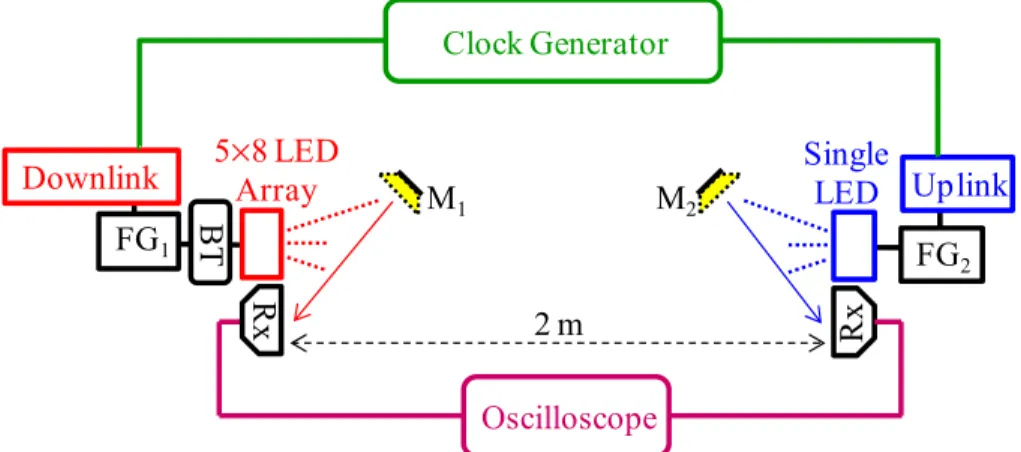
Figure 1 shows the experimental setup of our proposed TDD VLC system. The downlink message and uplink message were generated by function generator 1 (FG1, Agilent 33220A)
and function generator 2 (FG2, Agilent 33120A), respectively. A clock generator produced a
12 kHz square wave with duty cycle close to 50%, which was used for triggering both function generators in burst mode. Here, FG1 and FG2 were triggered by falling edge and
The PIN Rxs (ThorLabs PDA36A) were employed to measure the uplink and downlink signals. The PIN Rx has the detection wavelength range of 350 − 1100 nm with responsivity of 0.65 A/W and active area of 13 mm2. Its bandwidth is 17 MHz and the root mean square
(rms) noise is 530 μV. They were connected to a real-time oscilloscope (Tektronix, TDS2022B). The bandwidth of the oscilloscope is 100 MHz, with vertical resolution of 9-bit and sample rate of 1.25 GSa/s. To analyze and measure the reflection interference in the experiment, two glass mirrors with an area of 64 cm2 were placed at M
1 or M2, respectively,
as illustrated in Fig. 1. They are placed at about 25 cm away from the LED Tx. By tuning the mirror angles, the interference power could be adjusted accordingly.
Downlink 5×Array8 LED
Rx BT M1 Rx M2 Single LED FG1 FG 2 Downlink Uplink Clock Generator Oscilloscope 2 m
Fig. 1. Experimental Setup for the TDD VLC system: M: mirror; FG: function generator; Rx: receiver; BT: bias-tee.
2. Measurement results
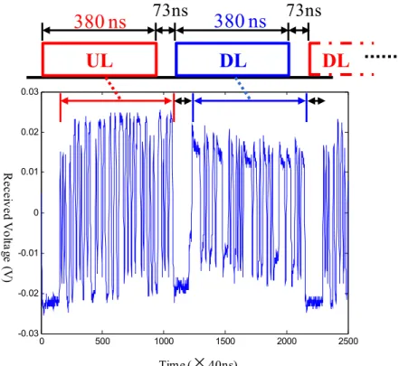
Figure 2 shows the time slot assigned for the uplink (UL) and downlink (DL) signals. Each signal contains 95 symbols and the corresponding time-interval is 380 ns. The guard time between uplink and downlink is approximately 73 ns. The measured time domain waveforms for both uplink and downlink are included. The experiment results verified that this interval was long enough to prevent crosstalk in the proposed system.
The reflection interference analysis of the uplink signal quality was performed by putting the glass mirror at position M1 as shown in Fig. 1. Figure 2 shows the measured time domain
waveform of the upstream Rx. Both uplink and downlink signals can be received. The uplink signal was the target signal to be received, and the downlink signal (the unwanted and interference signal) can be identified in time-domain when TDD was used. The uplink and downlink bursts were properly separated in time domain with sufficient guard time. The received waveform showed that the reflected interference signal (downlink) from the mirror generated a significant interference signal power. By turning off the time slot of the received interference signal, the performance of the uplink signal can be significantly improved.
0 500 1000 1500 2000 2500 -0.03 -0.02 -0.01 0 0.01 0.02 0.03
UL
DL
DL
380 ns
73ns
380 ns
73ns
Time ( 40ns)×
Rec ei ved V olt ag e (V )Fig. 2. The received time domain waveform by upstream Rx with assigned time slot for uplink, downlink and guard time.
(a)
(b)
Fig. 3. Eye-diagram with TDD system used (a) Downlink (b) Uplink.
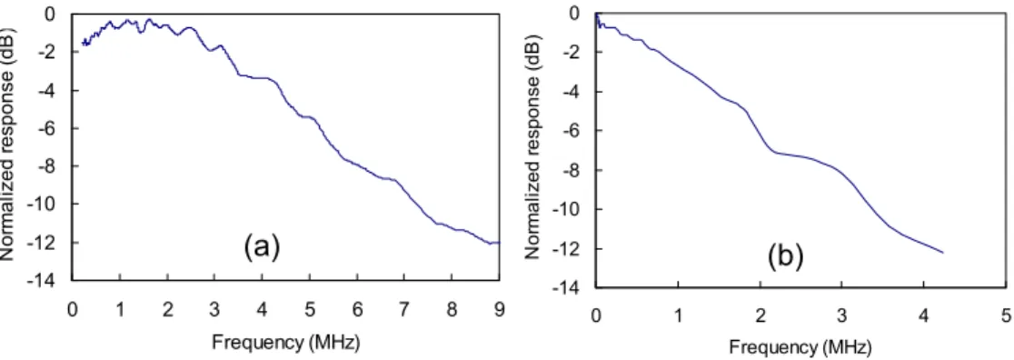
V). Hence we observe a low frequency cut-off in Fig. 4(a). For driving the single-LED, the DC-bias was provided from the FG. The frequency response curves also explain the eye-shapes of the downlink and uplink signals as shown in Fig. 3(a) and 3(b) respectively. We can observe that the rise-time and fall-time of the downlink signal are faster due to the higher modulation bandwidth of the downlink channel.
-14 -12 -10 -8 -6 -4 -2 0 0 1 2 3 4 5 6 7 8 9 Frequency (MHz) N or m al iz ed r es ponse (dB ) -14 -12 -10 -8 -6 -4 -2 0 0 1 2 3 4 5 Frequency (MHz) N o rma liz e d re sp o n se (d B ) (a) (b)
Fig. 4. Frequency response curves of the (a) Downlink (b) Uplink
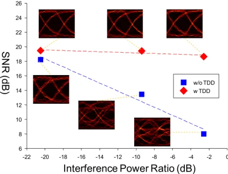
Then, we analyzed the influence of reflection interference. The uplink path was selected in this analysis, and it is worth to note that uplink and downlink channels behaved similarly. Figure 5 shows the measured signal-to-noise ratio (SNR) of the uplink signal under different interference power ratios with and without the TDD mode. The SNR was estimated by calculating the mean and variance of the received uplink signal voltage. The interference power ratio was defined as the power ratio of the interference signal to the uplink signal. We can observe that the SNR deteriorates with the increase in the interference power without using the TDD mode. At the interference power ratio of −2.5 dB, the SNR of the uplink signal dropped to 8 dB. By using the TDD mode, the uplink signal was not affected by the reflected interference signal even at a very high interference power ratio of −2.5 dB. The SNR of the uplink signal was maintained at about 19 dB, which corresponded to the BER of < 10−5. We
can also observe from Fig. 5 that the change of the uplink signal SNR was negligible under different interference power ratios, showing the proposed scheme can significantly eliminate the reflection interference even at high reflection power.
Interference Power Ratio (dB)
-22 -20 -18 -16 -14 -12 -10 -8 -6 -4 -2 0SN
R
(dB)
6 8 10 12 14 16 18 20 22 24 26 w/o TDD w TDDFig. 5. SNR over different interference power ratio with and without using TDD. 4. Conclusion
One of the most challenging issues for the in-home and in-building LED VLC deployment is the provision of an uplink path. Previous works using modulated retro-reflector, RF and using black adhesive-tape to block the downlink signals from entering the uplink Rx have been proposed, but have different limitations.
In this work, we experimentally demonstrated a bi-directional transmission link using LED VLC in both downlink and uplink paths. TDD was proposed and demonstrated to significantly eliminate the reflection interference in VLC. A free space bi-directional transmission of 2 m using simple OOK modulation with BER of < 10−5 in both directions was
achieved. Moreover, the influence of reflection interference is analyzed. By using the TDD mode, the uplink signal was not affected by the reflected interference signal even at very high interference power ratio of −2.5 dB. The SNR of the uplink signal was maintained at about 19 dB, and the change of the uplink signal SNR was negligible under different interference power ratios. If the TDD mode was not used, the SNR degraded with the increase in the interference power. Thus, at the interference power ratio of −2.5 dB, the SNR of the uplink signal dropped to 8 dB.