應用於無線多輸入多輸出基頻處理器之頻率相依的IQ不平衡效應之研究
42
0
0
全文
(2) 應用於無線多輸入多輸出基頻處理器之 頻率相依的 IQ 不平衡效應之研究 The Study of All-Digital Compensation for I/Q Mismatch with Frequency Dependent Imbalance in MIMO-OFDM Baseband Designs. 研 究 生:賴煒棋. Student:Wei-Chi Lai. 指導教授:許騰尹. Advisor:Terng-Yin Hsu. 國 立 交 通 大 學 資 訊 科 學 與 工 程 研 究 所 碩 士 論 文. A Thesis Submitted to Institute of Computer Science and Engineering College of Computer Science National Chiao Tung University in partial Fulfillment of the Requirements for the Degree of Master in Computer Science June 2006 Hsinchu, Taiwan, Republic of China. 中華民國九十五年六月.
(3) 應用於無線多輸入多輸出基頻處理器之 頻率相依的 IQ 不平衡效應之研究 學生:賴煒棋. 指導教授:許騰尹 博士 國立交通大學. 資訊學院 資訊工程學系碩士班. 摘要 直接降頻的接收器(DCR)架構目前在工業和學術界已經成為一個趨勢,因為它擁 有體積小,便宜和消耗更少動力的優勢。但是,這種架構會一起伴隨著一些射頻(RF) 的不完美效應,像是直流電(DC)偏移,頻率偏移,以及 I/Q 不平衡效應等等…在這篇 論文中,主要是研究頻率相依的 I/Q 不平衡效應。 為了使無線接收器上的類比 I/Q 處理器得到令人滿意的效能,實部和虛部的匹配 變得至關重要。 此論文提出一個新穎的基頻處理方法來估計和補償在 MIMO-OFDM 系統下,頻率相依的 I/Q 不平衡效應。 提出的方法只要使用一次的估算,就能夠估計 並且補償非理想效應,它可以容忍的範圍包含了震幅誤差 2dB, 相位誤差 20 度,以 及實部的低通濾波器是 [1 0.1 ],虛部的低通濾波器是 [0.1 1 ] 的情況。. i.
(4) The Study of All-Digital Compensation for I/Q Mismatch with Frequency Dependent Imbalance in MIMO-OFDM Baseband Designs Student:Wei-Chi Lai. Advisor:Terng-Yin Hsu. Department of Computer Science and Information Engineering, National Chiao Tung University. Abstract A direct-conversion receiver (DCR) architecture becomes a trend in industry and academic world nowadays because it is small, cheap and less power-consuming. This kind of architecture, however, accompanies with some radio frequency (RF) imperfections such as the direct current (DC) offset, frequency offset, inphase/quadrature (I/Q) imbalance, and etc. In this thesis, it focuses on the topic of the RF impairment of frequency dependent I/Q imbalance. To achieve satisfactory performance in analog I/Q (inphase/quadrature) processing based wireless receivers, the matching of amplitudes and phases of the I and Q branches becomes vital. In this thesis, a novel baseband I/Q estimation and compensation technique is proposed to overcome the frequency dependent I/Q imbalance in MIMO-OFDM systems. The proposed method uses a one-shot algorithm which is able to estimate and compensate the non-ideal effect up to gain error 2 dB, phase error 20 degree, and the low pass filter of the real part is [1 0.1], the low pass filter of the image part is [0.1 1].. ii.
(5) Acknowledgment. This thesis describes research work I performed in the Integration System and Intellectual Property (ISIP) Lab during my graduate studies at National Chiao Tung University (NCTU). This work would not have been possible without the support of many people. I would like to express my most sincere gratitude to all those who have made this possible. First and foremost I would like to thank my advisor Dr. Terng-Yin Hsu for the advice, guidance, and funding he has provided me with. I feel honored by being able to work with him and look forward to a continued research relationship for my Ph.D. I am very grateful to You-Hsien Lin, Ming-Fu Sun and the members of ISIP Lab, Jyun-Rong Li, Ta-Young Juan, Li-Sheng Lu, Wei-Ren Wang for their support and suggestions. Finally, and most importantly, I want to thank my parents for their unconditional love and support they provide me with. It means a lot to me.. Wei-Chi Lai July 2006. iii.
(6) Contents. page. Chinese Abstract........................................................................................................ i English Abstract.........................................................................................................ii Acknowledgment.......................................................................................................iii Contents.....................................................................................................................iv List of Figures.............................................................................................................v List of Tables.............................................................................................................vii Abbreviations..........................................................................................................viii CHAPTER 1 INTRODUCTION ............................................................................................1 CHAPTER 2 SYSTEM MODEL OF MIMO-OFDM ..........................................................4 CHAPTER 3 GENERAL I/Q IMBALANCED MODEL.....................................................7 CHAPTER 4 ESTIMATION FOR FREQUENCY DEPENDENT I/Q IMBALANCE ..11 CHAPTER 5 SIMULATION RESULT AND PERFORMANCE .....................................17 CHAPTER 6 PROPOSED HARDWARE ARCHITECTURE ..........................................25 CHAPTER 7 CONCLUSION AND FUTURE WORK ......................................................29 REFERENCES.......................................................................................................................30. iv.
(7) List of Figures. page. FIGURE 2-1 MIMO BASIC ARCHITECTURE ..............................................................................4 FIGURE 2-2 ALAMOUTI STBC(SPACE TIME BLOCK CODE) ................................................5 FIGURE 2-3 MIMO BASIC TRANSMITTER ................................................................................5 FIGURE 2-4 MIMO BASIC RECEIVER.......................................................................................5 FIGURE 2-5 SYSTEM CHANNEL MODEL ...................................................................................6 FIGURE 3-1 MIMO-OFDM I/Q SYSTEM MODEL.....................................................................8 FIGURE 3-2 AMPLITUDE OF C.F.R.OF GAIN ERROR 1DB, PHASE ERROR 20°............................9 FIGURE 3-3 PHASE OF C.F.R. OF GAIN ERROR 1DB, PHASE ERROR 20° ...................................9 FIGURE 3-4 AMPLITUDE OF CHANNEL FREQUENCY RESPONSE OF. hI (t ) =[1 0.1], hQ (t ) =[0.1 1], GAIN ERROR 1DB, PHASE ERROR 20° ...............10 FIGURE 3-5 PHASE OF CHANNEL FREQUENCY RESPONSE OF. hI (t ) =[1 0.1], hQ (t ) =[0.1 1] , GAIN ERROR 1DB, PHASE ERROR 20°...............10 FIGURE 4-1 MIMO-OFDM PACKET FORMAT ........................................................................11 FIGURE 4-2 HT-LTF TONE INTERLEAVING ACROSS 4 SPATIAL STREAMS .................................12 FIGURE 4-3 HT-LTF TONE INTERLEAVING ACROSS 2 SPATIAL STREAMS .................................12 FIGURE 4-4 FLOW CHART OF PROPOSED ALGORITHM ............................................................16 FIGURE 5-1 AMPLITUDE OF C.F.R. Hˆ 11 ( hI (t ) =[1 0.1], hQ (t ) =[0.1 1] , 1DB 20° ) .................18 FIGURE 5-2 PHASE OF C.F.R. Hˆ 11 ( hI (t ) =[1 0.1], hQ (t ) =[0.1 1] , 1DB 20° ) .......................18 FIGURE 5-3 AMPLITUDE OF CHANNEL FREQUENCY RESPONSE Hˆ 11 IN TGNE .........................19 FIGURE 5-4 PHASE OF CHANNEL FREQUENCY RESPONSE Hˆ 11 IN TGNE ..................................19. v.
(8) FIGURE 5-5 AMPLITUDE OF CHANNEL FREQUENCY RESPONSE OF TGND ..............................20 FIGURE 5-6 PER VS SNR, MCS 13, TGND, 1DB 10° AND 0.7DB 8°......................................20 FIGURE 5-7 PER VS SNR, MCS 13, TGND, 1DB 20° AND 2DB 10°.......................................21 FIGURE 5-8 AMPLITUDE OF CHANNEL FREQUENCY RESPONSE OF TGNE ..............................21 FIGURE 5-9 PER VS SNR, MCS 13, TGNE, 1DB 10° AND 0.7DB 8° ......................................22 FIGURE 5-10 PER VS SNR, MCS 13, TGNE, 1DB 20° AND 2DB 10° .....................................22 FIGURE 5-11 AMPLITUDE OF CHANNEL FREQUENCY RESPONSE OF TGNF.............................23 FIGURE 5-12 PER VS SNR, MCS 13, TGNF, 1DB 10° AND 0.7DB 8°.....................................23 FIGURE 5-13 PER VS SNR, MCS 13, TGNF, 1DB 20° AND 2DB 10°......................................24 FIGURE 6-1 BLOCK DIAGRAM OF THE PROPOSED I/Q ESTIMATOR & COMPENSATION ............25 FIGURE 6-2 BLOCK OF IQ-ESTIMATION .................................................................................26 FIGURE 6-3 BLOCK OF IQ-COMPENSATION ............................................................................26 FIGURE 6-4 BLOCK STRUCTURE OF I/Q-ESTIMATION.............................................................27 FIGURE 6-5 BLOCK STRUCTURE OF I/Q-COMPENSATION. ......................................................28. vi.
(9) List of Tables. page. TABLE 1-1 THE STATE OF THE ART ..........................................................................................3 TABLE 4-1 TONE PARTITIONING INTO SETS FOR 20MHZ (56 TONES).......................................12 TABLE 5-1 TGN MULTIPATH SPECIFICATIONS .........................................................................18 TABLE 7-1 COMPARISON WITH OTHER METHODS ...................................................................29. vii.
(10) Abbreviations. AWGN. additive white Gaussian noise. BPSK. binary phase shift keying. CFO. carrier frequency offset. DFT. discrete Fourier transform. DVB-T. digital video broadcasting terrestrial TV. FFT. fast Fourier transform. IFFT. inverse fast Fourier transform. I/Q. in phase/quadrature phase. I/Q-M. I/Q mismatch. FDI. frequency dependent imbalance. LO. local oscillator. MIMO. multi-input multi-output. OFDM. orthogonal division frequency modulation. PER. packet error rate. PPDU. PLCP protocol data unit. PSDU. PHY service data unit. RF. radio frequency. SNR. signal-to-noise ration. WLAN. wireless local area network. viii.
(11) CHAPTER 1 INTRODUCTION Orthogonal Frequency Division Multiplexing (OFDM) is a kind of spectrally efficient signaling technique for communications over frequency selective fading channels [1], [2]. MIMO-OFDM is one of the promising technologies satisfying the need for high throughput. Orthogonal frequency division multiplexing (OFDM) possesses the ability to resist multipath channel by simple frequency-domain equalizer; thus, it has been adopted by many transmission systems, e.g., IEEE802.11a/g based WLAN systems [3], [4], digital audio broadcasting (DAB) [5], and digital video broadcasting terrestrial TV (DVB-T) [6]. Unfortunately, OFDM systems are sensitive to imperfect synchronization and non-ideal front-end effects, causing serious system performance degradation. One of the key effects coming from non-ideal RF circuit is I/Q imbalance, which is due to the gain and phase mismatch between in-phase (I) and quadrature-phase (Q) paths. More specifically, it occurs when the difference of the phase in I and Q channels from local oscillator is not exactly 90 degree and the gain is not the same. In this thesis, we propose a novel one-shot frequency domain technique for calibrate frequency dependent I/Q imbalance in MIMO-OFDM systems. Multiple-input multiple-output (MIMO) makes use of multiple transmitter and multiple receiver antennas to transmit independent data streams simultaneously for increasing diversity and spectral efficiency. Consequently, the combination of MIMO and OFDM is widely discussed in recent years and has been used by some wireless broadband systems such as IEEE 802.11n [7] and IEEE.802.16a. In fact, there are tons of literatures focusing on the problem of I/Q imbalance and the compensation scheme; see [9]-[24] and references therein. However, most of them put emphasis on frequency-independent I/Q imbalance, and only a few of them [9], [12]-[17] provide compensation schemes for frequency-dependent I/Q imbalance, which is much more complicated. Based on the assumption that desired signal and image interference are statistically independent, some methods make use of the blind source separation techniques. 1.
(12) to extract the desired signal [9][12][18][19]. However, the finite training sequences used to estimate the coefficients for compensation do not always satisfy the assumption. Therefore, decision-directed methods are usually needed for these algorithms to adaptively converge the desired solutions. Some other adaptive compensation methods, such as [20], also encounter the same difficulty. Then, [16] deriving an adaptive MMSE solution and I/Q mismatch cancellation in frequency domain for MIMO-OFDM systems. It independently calculates the coefficients of detection and compensation for each subcarrier, but the coefficients of neighboring subcarriers are highly correlated. Accordingly, we should take account of this property to improve speed of convergence. On the other hand, some researchers develop the compensation algorithms by means of the training symbols known by the receiver in advance, like [21]-[24]. Reference [21] analyzes the frequency-dependent I/Q imbalance in the presence of frequency-offset. Still, some restrictions on the training sequence exist and a finite impulse response (FIR) filter is adopted to correct the frequency-dependent I/Q mismatch. Truly, a FIR filter is not suitable for OFDM systems because it increases the effective channel length experienced by transmitted signal. If the effective channel length is larger than the guard interval (GI), we have to show the great concern about the inter-symbol interference (ISI) which is a troublesome issue in OFDM systems. Then, speaking of Reference [22], it only discusses frequency-independent I/Q imbalance problem on the basis of channel smoothness criterion. Moreover, both [21] and [22] ignore the noise contribution when they analyze these RF imperfections, and it doesn’t conform to the real case. Different from [21] and [22], assuming the noise at receiver is an additive white Gaussian noise (AWGN), references [23] [24] propose techniques that jointly estimates the I/Q imbalance and other RF impairments based on the maximum likelihood (ML) criterion. However, the joint estimators of [23][24] are only for the frequency-independent I/Q mismatch and can not be directly applied to MIMO-OFDM systems. In order to maintain and realize system with imperfect RF distortions, we major focus on “how to calibrate the frequency dependent I/Q imbalance accuracy”. Table 1-1 shows the state of the art of the I/Q-M problem in OFDM system. And in this thesis, the proposed algorithm using the long training field preamble in MIMO-OFDM packet format is developed to overcome frequency dependent I/Q-M. From simulation results, it is shown that the proposed scheme make a high performance receiver possible in the condition of frequency dependent I/Q-M.. 2.
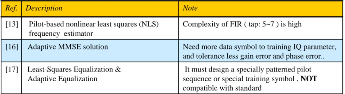
(13) Ref.. Description. Note. [13]. Pilot-based nonlinear least squares (NLS) frequency estimator. Complexity of FIR ( tap: 5~7 ) is high. [16]. Adaptive MMSE solution. Need more data symbol to training IQ parameter, and tolerance less gain error and phase error... [17]. Least-Squares Equalization & Adaptive Equalization. It must design a specially patterned pilot sequence or special training symbol , NOT compatible with standard. Table 1-1 The State of The Art. The remainder of this thesis is organized as follows. Chapter 2 describes the MIMO-OFDM system model. Chapter 3 describes the general I/Q Imbalance Model. Then a novel algorithm for compensating for frequency dependent I/Q-M is developed in Chapter 4. The simulation results are shown in Chapter 5. Proposed hardware architecture is in Chapter 6. Finally, this thesis is concluded in Chapter 7 And reference is in the last part of this thesis.. 3.
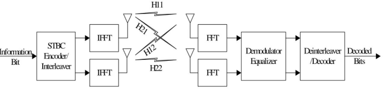
(14) CHAPTER 2 SYSTEM MODEL OF MIMO-OFDM The MIMO-OFDM system supports BPSK、QPSK、16-QAM、64-QAM four kinds of modulation, FEC supports 1/2、2/3、3/4、5/6 four kinds of coding rate,and it can uses 2x2 or 4x4 antennas to transmit data. Before data transmitted, the data must go through Alamouti STBC(Space Time Block Code)encoding. After that, data go through OFDM modulation, and using IFFT to transfer frequency domain data to time domain signal. In each OFDM symbol, each symbol has 64 subcarriers , and 52 of them are data carrier, 4 of them are pilot carrier, others are null carrier. In receiver, first step, it uses FFT to transfer received signal to frequency domain data. Second step, equalizer will compensate channel effect then combine two stream data into original by Alamouti Decoder. The MIMO basic architecture is as Figure 2-1 and the Alamouti STBC(Space Time Block Code)is as Figure 2-2.The basic MIMO-OFDM transmitter and receiver is as Figure 2-3 and Figure 2-4 [7]. And Figure 2-5 shows the used system channel model. In this thesis, we will focus on the I/Q mismatch, and the general I/Q model will be introduced in next section in detail.. H11 H2 1. IFFT Information Bit. STBC Encoder/ Interleaver. FFT 2 H1. IFFT. Demodulator Equalizer. H22. FFT. Figure 2-1 MIMO Basic Architecture. 4. Deinterleaver Decoded /Decoder Bits.
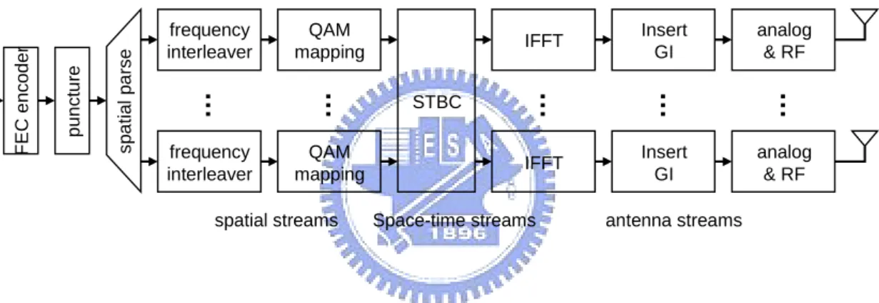
(15) time1. time2. X1D − X. h2,1. X 2D. X1*D. time2. time1. h1,1. * 2D. Y = X1D H11 + X 2 D H12 + W 1 1. 1 1. Y = − X H11 + X1*D H12 + W21 1 2. * 2D. h1,2 Y12 = X1D H21 + X 2 D H22 + W12 Y22 = − X 2*D H21 + X1*D H22 + W22. h2,2. spatial parse. puncture. QAM mapping. STBC. spatial streams. analog & RF. …. …. frequency interleaver. Insert GI. IFFT. …. QAM mapping. …. frequency interleaver. …. FEC encoder. Figure 2-2 Alamouti STBC(Space Time Block Code). IFFT. Insert GI. analog & RF. Space-time streams. antenna streams. spatial merge. de-interleaver. de-map. spatial streams. Figure 2-4. IQ Est. & IQ Comp.. Space-time streams. channel estimate FFT. sync. analog & RF. antenna streams. MIMO Basic Receiver. 5. analog & RF. …. STBC decoder. sync. …. de-puncture. FFT. de-map. …. Viterbi decode. de-interleaver. …. output. de-scramble. Figure 2-3 MIMO Basic Transmitter.
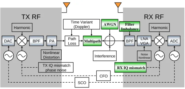
(16) TX RF. RX RF Time Variant (Doppler). Harmonic. DAC. BPF. PA. Path Loss. AWGN. Multipath. Nonlinear Distortion. Filter Imbalance BPF. RX IQ mismatch CFO SCO. Figure 2-5. LNA VGA Noise Nonlinear. Interference. TX IQ mismatch phase noise. Harmonic. System Channel Model. 6. ADC.
(17) CHAPTER 3 GENERAL I/Q IMBALANCED MODEL A generalized block-diagram of an I/Q signal processing based quadrature receiver [9] is presented in Figure 3-1.The I/Q imbalance caused by the LO can be characterized by an amplitude mismatch g = (1+ ε ) and a phase error θ . Following the LO are mixers, amplifiers, LPFs and A/D converters which in general cause the frequency dependent I/Q imbalance. And we represent the I/Q baseband signal paths by two mismatched LPFs (with frequency responses of H I ( f ) and H Q ( f ) ,respectively) [9]. The local oscillator signal X LO (t ) of an imbalanced quadrature demodulator is here modeled as:. X LO (t ) = I LO (t ) + jQLO (t ) = cos(2π f ct ) − jg sin(2π f ct + θ ) = K1e− j 2π fct + K2e j 2π fct. = K1 z (t ) + K 2 z * (t ). ( 3-1 ). Where g = (1+ ε ) and θ represent the demodulator amplitude and phase imbalances, respectively (ideally g = 1 and θ = 0 ). The mismatch coefficients K1 and K2 in ( 3-1 ) are given by. K1 = [1 + ge − jθ ] / 2. ( 3-2a ). K 2 = [1 − ge jθ ] / 2. ( 3-2b ). 7.
(18) From [9], to analyze the effect of branch mismatches, the signal after through LPFs, and Fourier transforms, we can get. RBB ( f ) = I BB ( f ) + jQBB ( f ) = I LO ( f ) H I ( f ) + jQLO ( f ) H Q ( f ). ( 3-3 ). RBB ( f ) represents the received data in the baseband as in Fig.3-1 .After some manipulations, the result of ( 3-3 ) can be written in a more convenient form as. RBB ( f ) = α ( f ) Z ( f ) + β ( f ) Z * ( − f ) Where. ( 3-4 ). α ( f ) = [ H I ( f ) + H Q ( f ) ge− jθ ]/ 2. ( 3-5a ). β ( f ) = [ H I ( f ) − H Q ( f ) ge jθ ]/ 2 ( 3-5b ). I LO (t ) = cos(2π f c t ). I BB (t ). H I (t ) Z (t ) 90°+ θ. QLO (t ) = −(1 + ε ) sin(2π f c t + θ ) LPF. 1+ε Figure 3-1. ADC. H Q (t ). QBB (t ). MIMO-OFDM I/Q System Model.. 8. Baseband. ADC. LPF. RBB (t ).
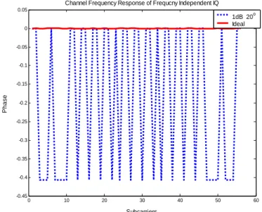
(19) In ( 3-4 ), the term relative to Z * (− f ) is caused by the imbalances and represents the image aliasing effect. Notice that the basic imbalance model used in [10]-[11] is a special case of ( 3-4 ) for which H I ( f ) = H Q ( f ) . And because the front-end processing cannot sufficiently attenuate the image band signal and some kind of compensation is needed. Following figures show how the frequency independent I/Q-M and frequency dependent I/Q-M affect the channel frequency response in the condition of No Multipath, and No AWGN. In Figure 3-2 and Figure 3-3, it shows the amplitude and phase of the channel frequency response under the condition of frequency-independent I/Q-M of gain error 1dB, phase error 20°. 1dB, 20 Ideal. Channel Frequency Response of Independent IQ 1.2. o. Amplitude. 1.15. 1.1. 1.05. 1. 0.95. 0. 10. 20. 30. 40. 50. 60. Subcarriers. Amplitude of C.F.R. of Gain Error 1dB, Phase Error 20°. Figure 3-2. Channel Frequency Response of Frequcny Independent IQ 0.05. 1dB 20 Ideal. 0. o. -0.05. -0.1. Phase. -0.15. -0.2. -0.25. -0.3. -0.35. -0.4. -0.45. 0. 10. 20. 30. 40. 50. 60. Subcarriers. Figure 3-3. Phase of C.F.R. of Gain Error 1dB, Phase Error 20°. 9.
(20) In Figure 3-4 and Figure 3-5, it shows the amplitude and phase of the channel frequency. response under the condition of frequency dependent I/Q-M of gain error 1dB, phase error 20°, hI (t ) =[1 0.1], hQ (t ) =[0.1 1].. Channel Frequency Response of Frequency Dependent IQ 1.5 1dB 20o ;HI=[1 0.1] HQ=[0.1 1] 1.4. Ideal. 1.3. 1.2. Amplitude. 1.1. 1. 0.9. 0.8. 0.7. 0.6. 0.5. 0. 10. 20. 30. 40. 50. 60. Subcarriers. Figure 3-4. Amplitude of C.F.R. of hI (t ) =[1 0.1], hQ (t ) =[0.1 1], Gain Error 1dB, Phase Error 20°. Channel Frequency Response of Frequency Dependent IQ 3 o. 1dB 20 ; HI=[1 0.1] HQ=[0.1 1] Ideal 2. Phase. 1. 0. -1. -2. -3. 0. 10. 20. 30. 40. 50. 60. Subcarriers. Figure 3-5. Phase of C.F.R. of hI (t ) =[1 0.1], hQ (t ) =[0.1 1] , Gain Error 1dB, Phase Error 20°. 10.
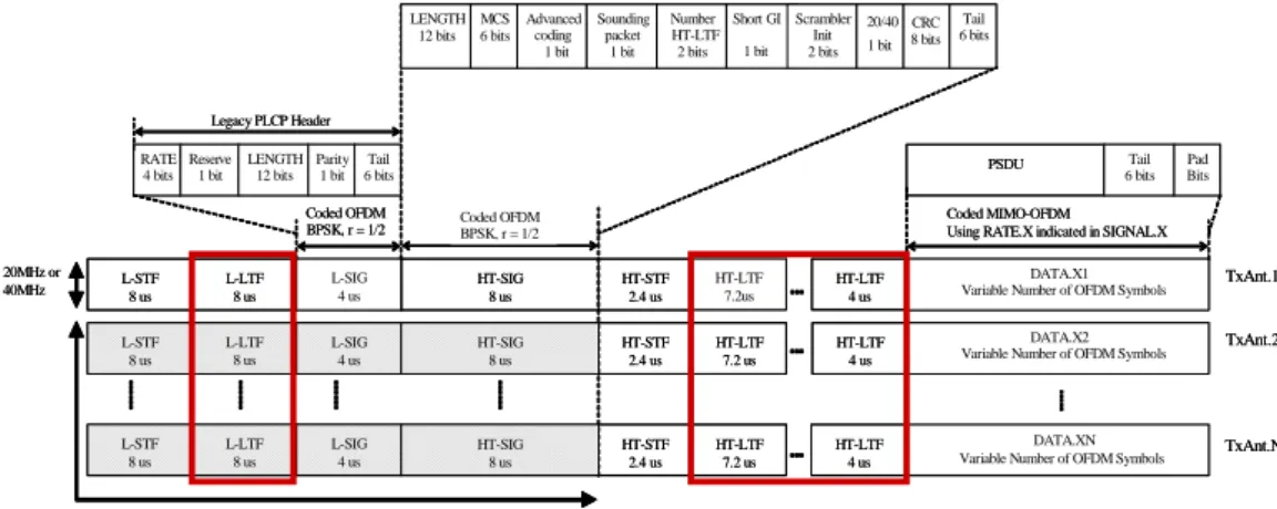
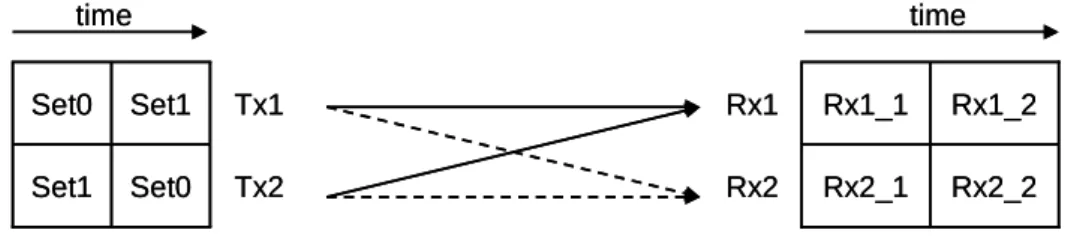
(21) CHAPTER 4 ESTIMATION FOR FREQUENCY DEPENDENT I/Q IMBALANCE In MIMO-OFDM system, the packet format is as Figure 4-1. The legacy long training OFDM symbol is identical to the 802.11a long training OFDM symbol [7]. And the L-LTF is the same in each antenna. The HT-LTFs are transmitted after the HT-STF. For any PPDU, there must be at least as many HT-LTFs as spatial streams in the HT Data portion of the PPDU. The first HT-LTF consists of two Long Training Symbols (LTS) as in 802.11a/g and a regular guard interval of 0.8 µs, giving a total length of 7.2µs. Following second and all subsequent HT-LTFs each consist of a single HT-LTS with a regular guard interval of 0.8 µs, giving a total length of 4µs. And the HT-LTF is tone interleaved across antennas, the 56 tones are partitioned across the antenna array during each OFDM symbol. Tone partitioning into sets for 20MHz is shown in Table 4-1. At each OFDM symbol interval, each set of tones maps to one transmit antenna. And over time, all sets get mapped to an antenna. An example of tone interleaving across 4 transmit antennas is shown in Figure 4-2 [7]. And Figure 4-3 shows the HT-LTF tone interleaving across 2 spatial streams.. LENGTH MCS 12 bits 6 bits. Advanced coding 1 bit. Sounding packet 1 bit. Number Short GI Scrambler HT-LTF Init 1 bit 2 bits 2 bits. 20/40 CRC 1 bit 8 bits. Tail 6 bits. Legacy PLCP Header RATE Reserve 4 bits 1 bit. 20MHz or 40MHz. LENGTH Parity Tail 12 bits 1 bit 6 bits. PSDU. Coded OFDM BPSK, r = 1/2. Coded OFDM BPSK, r = 1/2. Tail 6 bits. Pad Bits. Coded MIMO-OFDM Using RATE.X indicated in SIGNAL.X. L-STF 8 us. L-LTF 8 us. L-SIG 4 us. HT-SIG 8 us. HT-STF 2.4 us. HT-LTF 7.2us. HT-LTF 4 us. DATA.X1 Variable Number of OFDM Symbols. TxAnt.1. L-STF 8 us. L-LTF 8 us. L-SIG 4 us. HT-SIG 8 us. HT-STF 2.4 us. HT-LTF 7.2 us. HT-LTF 4 us. DATA.X2 Variable Number of OFDM Symbols. TxAnt.2. L-STF 8 us. L-LTF 8 us. L-SIG 4 us. HT-SIG 8 us. HT-STF 2.4 us. HT-LTF 7.2 us. HT-LTF 4 us. DATA.XN Variable Number of OFDM Symbols. TxAnt.Ntx. Shaded fields transmitted as CDD (optional). Figure 4-1. MIMO-OFDM Packet Format. 11.
(22) Nss. Set 0. Set 1. Set 2. Set 3. 1. [-28:1:-1] [1:1:+28]. 2. [-28:2:-2] [2:2:28]. [-27:2:-1] [1:2:27]. 3. [-28:3:-1] [2:3:26]. [-27:3:-3] [3:3:27]. [-26:3:-2] [1:3:28]. 4. [-28:4:-4] [1:4:25]. [-27:4:-3] [2:4:26]. [-26:4:-2] [3:4:27]. [-25:4:-2] [4:4:28]. Table 4-1 Tone partitioning into sets for 20MHz (56 tones). HT-LTF 0. HT-LTF 1. HT-LTF 2. HT-LTF 3. SS 0. Set 0. Set 3. Set 2. Set 1. SS 1. Set 1. Set 0. Set 3. Set 2. SS 2. Set 2. Set 1. Set 0. Set 3. SS 3. Set 3. Set 2. Set 1. Set 0. time. Figure 4-2. HT-LTF tone interleaving across 4 spatial streams. time. time. Set0. Set1. Tx1. Rx1. Rx1_1. Rx1_2. Set1. Set0. Tx2. Rx2. Rx2_1. Rx2_2. Figure 4-3. HT-LTF tone interleaving across 2 spatial streams. 12.
(23) From Figure 4-1 ~ Figure 4-3, we can get the Set0 and Set1 in 2x2 system.. –. Set_0 = [0. 0 -1. –. Set_1 = [0 -1. 0 1. 0 -1. 0 1. 0 -1. 0 -1 0 -1. 0. 0. 1. 0. 1. 0. ... ]. 1. 0 -1. 0. -1. ... ]. Because the data of Set0 and Set1 intersects, we can get the channel frequency response by interpolating the received data. And because the HT-LTF is tone interleaved across antennas, channel frequency response for each channel can be estimated by using the interpolating the received HT-LTF. Taking 2x2 system for example, these channel. frequency response Hˆ 11 ( f ) 、 Hˆ 12 ( f ) 、 Hˆ 21 ( f ) 、 Hˆ 22 ( f ) can be estimated.( Hˆ RT ( f ) means the estimating channel frequency response of Tth transmitter antenna to Rth receiver antenna ).From equation ( 3-4 ), the data affected by I/Q imbalance will be attenuated by its mirror part. In HT-LTF and L-LTF, there exit some pairs in which the quotient of data and its mirror part data is +1, and in others positions, their quotients are -1. Taking 2x2 systems for example, we can find some pairs which their quotient in HT-LTF is +1, and in L-LTF, in the same pair’s positions, their quotient is -1. In HT-LTF, the quotient of some pairs is +1, we can estimate the channel frequency response Hˆ 11 ( f ) 、 Hˆ 12 ( f ) 、 Hˆ 21 ( f ) 、 Hˆ 22 ( f ) from these pairs position as following.. Hˆ 11 ( f ) = α1 ( f ) H11 ( f ) + β1 ( f ) H11* (− f ). ( 4-1a ). Hˆ 12 ( f ) = α1 ( f ) H12 ( f ) + β1 ( f ) H12* (− f ). ( 4-1b ). * Hˆ 21 ( f ) = α 2 ( f ) H 21 ( f ) + β 2 ( f ) H 21 (− f ). ( 4-1c ). * Hˆ 22 ( f ) = α 2 ( f ) H 22 ( f ) + β 2 ( f ) H 22 (− f ). ( 4-1d ). Where. α1 ( f ) and β1 ( f ). means. the. I/Q-M. coefficients. in. receiver. one;. α 2 ( f ) and β 2 ( f ) means the I/Q-M coefficients in receiver two. And H11 ( f ) 、 H12 ( f ) 、 H 21 ( f ) 、 H 22 ( f ) represent the real channel frequency response.. In L-LTF, in the same pair’s positions, their quotient is -1. The L-LTF part in receiver one is as following.. 13.
(24) R1 ( f ) = α1 ( f ) { H11 ( f )L-LTF( f ) + H12 ( f )L-LTF( f )} + β1 ( f ) { H11* (− f )L-LTF* (− f ) + H12* (− f )L-LTF* (− f )}. ( 4-2 ). And because the L-LTF are all real number, L-LTF* ( f ) = L-LTF( f ) . After some rearrangement, equation ( 4-2 ) will become:. R1 ( f ) = α1 ( f ) H11 ( f )L-LTF( f ) + β1 ( f ) H11* (− f )L-LTF(− f ) +α1 ( f ) H12 ( f )L-LTF( f ) + β1 ( f ) H12* (− f )L-LTF(− f ). ( 4-3 ). And because L-LTF( − f ) = −1× L-LTF( f ) , equation ( 4-3 ) can be written as. R1 ( f ) = α1 ( f ) H11 ( f )L-LTF( f ) + β1 ( f ) H11* (− f ) [ L-LTF( f ) − 2L-LTF( f )]. +α1 ( f ) H12 ( f )L-LTF( f ) + β1 ( f ) H12* (− f ) [ L-LTF( f ) − 2L-LTF( f ) ] ( 4-4 ). Substituting equation ( 4-1a ) and ( 4-1b ) into equation ( 4-4 ), it will become…. R1 ( f ) = L-LTF( f ) Hˆ 11 ( f ) + L-LTF( f ) Hˆ 12 ( f ). −2 β1 ( f )L-LTF( f ) ⎣⎡ H11* (− f ) + H1*2 (− f ) ⎦⎤. ( 4-5 ). From equation ( 4-3 ) , and knowing L-LTF( f ) = −1× L-LTF( − f ) , getting the following... R1 ( f ) = α1 ( f ) H11 ( f ) [ L-LTF(− f ) − 2L-LTF(− f )] + β1 ( f ) H11* (− f )L-LTF(− f ). +α1 ( f ) H12 ( f ) [ L-LTF(− f ) − 2L-LTF(− f )] + β1 ( f ) H12* (− f )L-LTF(− f ) ( 4-6 ). Substituting equation ( 4-1a ) and ( 4-1b ) into equation ( 4-6 ), it will become…. R1 ( f ) = L-LTF( − f ) Hˆ 11 ( f ) + L-LTF( − f ) Hˆ 12 ( f ). −2α1 ( f )L-LTF(− f ) [ H11 ( f ) + H12 ( f )] 14. ( 4-7 ).
(25) After some rearrangement and making whole equation conjugate, equation ( 4-7 ) becomes:. R1* (− f ) = L-LTF* ( f ) Hˆ 1*1 (− f ) + L-LTF* ( f ) Hˆ 12* ( − f ) −2α1* (− f )L-LTF* ( f ) ⎡⎣ H11* (− f ) + H12* (− f ) ⎤⎦. ( 4-8 ). From equation ( 4-5 ) and ( 4-8 ), and L-LTF* ( f ) = L-LTF( f ) , we can get the following…. ( 4-9 ). And we can also find some pairs which their quotient in HT-LTF is -1, and in same pair’s positions in L-LTF, their quotient is +1. Follow the same method, we can find the equation below:. ( 4-10 ). From equation ( 4-9 ) and ( 4-10 ), there are 24 ratios of. β1 ( f ) in the receiver one in α1* (− f ). MIMO 2x2 systems of 20MHz. And by interpolating the 24 ratios, we can get the all ratios of 56 subcarriers of a symbol. After getting these 56 ratios, we can compensate the data of receiver one in frequency domain by the following equation.. α1* (− f ) R1 ( f ) − β1 ( f ) R1* (− f ) Z1 ( f ) = α1 ( f )α1* (− f ) − β1 ( f ) β1* (− f ) In the Receiver two, we can also take the same methods to get the 56 ratios of. ( 4-11 ). β2 ( f ) α 2* (− f ). to compensate for the frequency dependent I/Q-M in receiver two.. α 2* (− f ) R2 ( f ) − β 2 ( f ) R2* (− f ) Z2 ( f ) = α 2 ( f )α 2* (− f ) − β 2 ( f ) β 2* (− f ). 15. ( 4-12 ).
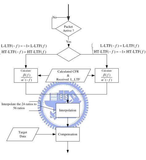
(26) Above equation from ( 4-1a ) to ( 4-12 ) is the case of 2x2 MIMO-OFDM systems in 20 MHz, we can also apply these one-shot method to solve the frequency dependent I/Q-M in MIMO-OFDM 4x4 systems. And following Figure 4-4 is the flow chart of the proposed algorithm.. No Packet Arrive ?. ⎧L-LTF(− f ) = −1× L-LTF( f ) ⎨ ⎩ HT-LTF(− f ) = HT-LTF( f ). Calculate. β( f ) α * (− f ). Interpolate the 24 ratios to 56 ratios. Target Data. Figure 4-4. Yes. Calculated CFR & Received L_LTF. L-LTF(− f ) = L-LTF( f ) ⎧ ⎨ − f ) = −1× HT-LTF( f ) HT-LTF( ⎩. Calculate. β( f ) α * (− f ). Interpolation. Compensation. Flow Chart of Proposed Algorithm. 16.
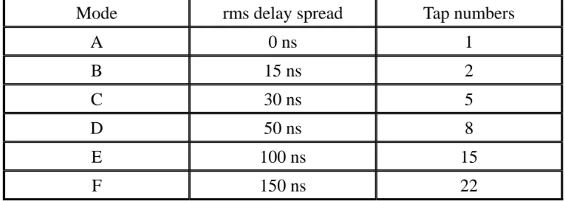
(27) CHAPTER 5 SIMULATION RESULT AND PERFORMANCE To evaluate the proposed algorithm, a typical MIMO-OFDM system based on IEEE P802.11 Wireless LANs, TGn Sync Proposal Technical Specification is used as a. reference-design platform. The parameters used in the simulation platform are “The length of OFDM symbol is 64 and cyclic prefix is 16”. A satisfactory accuracy can usually be reached if enough data samples are used to calculate the estimate from the long training symbols. As a result, the proposed method uses high throughput long training field symbols and legacy long training field symbols to measure the frequency dependent I/Q-M.. The simulation result below is based on following conditions: z. 2x2 MIMO-OFDM systems in 20MHhz.. z. PSDU is 1024. bytes. z. MCS is 13 (modulation is 64QAM, coding rate is 2/3 ). z. Decoder using soft Viterbi decoder. z. Multipath Model: TGnD, TGnE, TGnF, and the relative rms delay and Tap number will be shown in Table 5-1 [25]. We set three kinds conditions of I/Q Mismatch: High I/Q : gain error is 1dB, phase error is 20° in receiver 1; and gain error is 2dB, phase error is 10° in receiver 2. Low I/Q : gain error is 1dB, phase error is 10° in receiver 1; and gain error is 0.7dB, phase error is 8° in receiver 2.. Worst FDI (Frequency Dependent Imbalance): The hI (t ) represents the LPF in real part in time domain is [1 0.1] The hQ (t ) represents the LPF in image part in time domain is [0.1 1]. 17.
(28) Mode. rms delay spread. Tap numbers. A. 0 ns. 1. B. 15 ns. 2. C. 30 ns. 5. D. 50 ns. 8. E. 100 ns. 15. F. 150 ns. 22. Table 5-1 TGn Multipath Specifications. Following Figure 5-1 and Figure 5-2, it shows the amplitude and the phase of estimated channel frequency response Hˆ 11 under frequency dependent I/Q-M ( hI (t ) =[1 0.1], hQ (t ) =[0.1 1] ,. 1dB 20° ) , No AWGN, No Mutipath. 1.6 H11 before Compensation H11 after Compensation 1.4. amplitude. 1.2. 1. 0.8. 0.6. 0.4. 0.2. 0. 10. 20. 30. 40. 50. 60. subcarrier. Figure 5-1. Amplitude of C.F.R. Hˆ 11 ( hI (t ) =[1 0.1], hQ (t ) =[0.1 1] , 1dB 20° ). 3 H11 before Compensation H11 after Compensation 2. phase. 1. 0. -1. -2. -3. 0. 10. 20. 30. 40. 50. 60. subcarrier. Figure 5-2. Phase of C.F.R. Hˆ 11 ( hI (t ) =[1 0.1], hQ (t ) =[0.1 1] , 1dB 20° ). 18.
(29) From the above two figures, it shows that the I/Q-M has been calibrated, and the channel frequency response left can be compensated by the Aloumouti equalizer easily.. Following Figure 5-3 and Figure 5-4 , it shows the amplitude and the phase of estimated channel frequency response Hˆ 11 under frequency dependent I/Q-M ( hI (t ) =[1 0.1], hQ (t ) =[0.1 1] , 1dB 20° ) , Mutipath: TGnE, No AWGN.. H11 before Compensaion H11 after Compensaion H11 ideal. 2.2. 2. 1.8. 1.6. amplitude. 1.4. 1.2. 1. 0.8. 0.6. 0.4. 0.2. 0. 10. 20. 30. 40. 50. 60. subcarriers. Amplitude of Channel Frequency Response Hˆ 11 in TGnE. Figure 5-3. H11 before Compensation H11 after Compensation H11 ideal. 4. 2. 0. phase. -2. -4. -6. -8. -10. 0. 10. 20. 30. 40. 50. 60. subcarrier. Figure 5-4. Phase of Channel Frequency Response Hˆ 11 in TgnE. 19.
(30) Following figure will show the whole system performance ( PER ) improved by the proposed algorithms in all kinds of conditions. In Figure 5-5~ Figure 5-13, the multipath condition is TGnD or TGnE, or TGnF, Low I/Q or High I/Q, it shows that , the proposed algorithms can improve the system performance greatly when frequency dependent I/Q-M effect is serious.. Figure 5-5 Amplitude of Channel Frequency Response of TGnD. Figure 5-6. PER vs SNR, MCS 13, TGnD, 1dB 10° and 0.7dB 8°. 20.
(31) Figure 5-7. PER vs SNR, MCS 13, TGnD, 1dB 20° and 2dB 10°. Figure 5-8 Amplitude of Channel Frequency Response of TGnE. 21.
(32) Figure 5-9. PER vs SNR, MCS 13, TGnE, 1dB 10° and 0.7dB 8°. Figure 5-10 PER vs SNR, MCS 13, TGnE, 1dB 20° and 2dB 10°. 22.
(33) Figure 5-11 Amplitude of Channel Frequency Response of TGnF. Figure 5-12 PER vs SNR, MCS 13, TGnF, 1dB 10° and 0.7dB 8°. 23.
(34) Figure 5-13 PER vs SNR, MCS 13, TGnF, 1dB 20° and 2dB 10°. 24.
(35) CHAPTER 6 PROPOSED HARDWARE ARCHITECTURE Below Figure 6-1 shows the block diagram of the proposed I/Q estimator & compensation. And following Figure 6-2 and Figure 6-3 are the IQ-Estimation and IQ-Compensation block. And in Figure 6-4 and Figure 6-5, it shows the block architecture.. In this design, the critical module is the Complex Divider.. Data in AFC. Alamouti Equalizer. FFT. To FEC. IQ & Channel Estimation. Estimated IQ parameter IQ Compensation. Figure 6-1. Block Diagram of the proposed I/Q Estimator & Compensation. 25.
(36) L-LTF FFT_OUT_I L-LTF FFT_OUT_Q CFR_OUT_I IQ_ESTI. CFR_OUT_Q. IQ_ESTI_OUT1_I IQ_ESTI_OUT1_Q IQ_ESTI_OUT2_I IQ_ESTI_OUT2_Q. IQ ESTI_ENABLE IQ_ESTI_FINISH. CLK RST. Figure 6-2 Block of IQ-Estimation. IQ_ESTI_Parameter1_I. IQ_COMP_DATA_I IQ_COMP_DATA_Q IQ_COMP_FINISH. IQ_ESTI_Parameter1_Q IQ_ESTI_Parameter2_I IQ_ESTI_Parameter2_Q IQ_COMP. FFT_OUT_DATA_I FFT_OUT_DATA_Q IQ_COMP_ENABLE CLK RST. Figure 6-3. Block of IQ-Compensation. 26.
(37) Figure 6-4 Block Structure of I/Q-Estimation.. 27.
(38) Figure 6-5 Block Structure of I/Q-Compensation.. 28.
(39) CHAPTER 7 CONCLUSION AND FUTURE WORK This thesis has proposed a novel one-shot algorithm to estimate the frequency dependent I/Q-M in MIMO-OFDM receivers. The proposed algorithm can uses two kinds of long training symbols to estimate frequency dependent I/Q-M in multipath environments. From simulation results, the proposed algorithm can meet many system requirements to prevent obvious performance loss under different frequency dependent I/Q-M conditions. Following Table 7-1 shows the comparison result with other methods. Ref [16]. Ref [17]. Proposed work. Method. Nonlinear Least Squares (NLS) Frequency Estimator. Ref [13]. MMSE & RLS adaptive filter. Least-Squares Equalization & Adaptive Equalization. Using the preamble format different. Packet Frame Used. Pilot-based. Pilot-based. Training symbol or Pilot. HT-LTF & L-LTF. Consider Filter Imbalance ?. Yes. No. Yes. Yes,. Computational Effort. High. High. High. Low. Compatible for IEEE. Standard ?. Yes, compatible with IEEE. OFDM specification ( for 1x1 system ). Yes, compatible with IEEE. MIMO Standard specification. No, they have special design pilot or special training symbols. Yes, compatible with IEEE. MIMO Standard Specification. Performance. Average SNR loss is less 1dB (Channel condition is not clear). Improves within 2.5dB ( Need about 30-35 symbols for training ). Average SNR loss is about 2~3dB ( Need 10~40 training symbols ). In TGnD, filter imbalance IQ condition, the SNR loss is about 3dB. Table 7-1 Comparison with other Methods. 29.
(40) References [1] R. V. Nee and R. Parsed, OFDM for Wireless Multimedia Communication, MA: Artech House, 2000. [2] J. Heiskala and J. Terry, OFDM Wireless LANs: A Theoretical and Practical Guide, Sams, Indianapolis, Indiana, 2002. [3] Wireless LAN Medium Access Control (MAC) and Physical Layer (PHY) Specifications, IEEE Std 802.11a, 1999 [4] Wireless LAN Medium Access Control (MAC) and Physical Layer (PHY) Specifications, IEEE Std 802.11g, 2003 [5] Eur. Telecommun. Stand., Radio Broadcasting Systems: Digital Audio Broadcasting to Mobile, Portable and Fixed Receivers, Feb.1995. [6] Eur. Telecommun. Stand., Digital Vedio Broadcasting: Framing Structure, Channel Coding, and Modulation for Digital Terrestrial Television, Aug. 1997. [7] TGn Sync Group, IEEE P802.11 Wireless LAN - TGn Sync Proposal Technical Specification, Proposal of IEEE802.11n, IEEE Document 802.11-04/889r4, [8] January 2005.B. Cutler, “Effects of physical layer impairments on OFDM systems,” RF Design Magazine, May 2002. [9] M. Valkama , M. Renfors, and V. Koivunen, “Compensation of frequency-selective IQ imbalances in wideband receivers models and algorithms”, Wireless Communications, 2001. (SPAWC '01). 2001 IEEE Third Workshop on Signal Processing Advances in 20-23 March 2001 Page(s):42 – 45 [10] M. Valkama, and M. Renfors. “Advanced DSP for I/Q imbalance compensation in a low-IF receiver,” in Proc. IEEE Int. Conf. on Communications, New Orleans, LA,USA, Jun.2000.pp.768-772. [11] M. Valkama , M. Renfors, and V. Koivunen,,.”Blind source separation based I/Q imbalance compensation,” in Proc. IEEE Symposium 2000 on Adaptive Systems for Signal Processing, Communications and Control, Lake Louise, Alberta, Canada, Oct. 2000, pp 310-314.. 30.
(41) [12] K.P. Pun, J.E. Franca, C. Azeredo-Leme, C.F. Chan,C.S. Choy, “Correction of frequency-dependent I/Q mismatches in quadrature receivers,” IEEE Electronics Letters, Volume 37, Issue 23, Page(s):1415–1417, Nov 2001. [13] X. Guanbin, S. Manyuan, L. Hui, “Frequency offset and I/Q imbalance compensation for direct-conversion receivers,” IEEE Transactions Wireless Communications, Volume 4, Issue 2, Page(s):673–680, March 2005. [14] T.M. Ylamurto, “Frequency domain IQ imbalance correction scheme for orthogonal frequency division multiplexing (OFDM) systems,” IEEE Wireless Communications and Networking, Volume 1, Page(s):20–25, March 2003. [15] A. Schuchert, R. Hasholzner, P. Antoine, “A novel IQ imbalance compensation scheme for the reception of OFDM signals,” IEEE Transactions Consumer Electronics, Volume 47, Issue 3, Page(s):313–318, Aug. 2001. [16] R.M. Rao, B. Daneshrad, “I/Q mismatch cancellation for MIMO-OFDM systems,” 15th IEEE International Symposium Personal, Indoor and Mobile Radio Communications (PIMRC), Volume 4, Page(s):2710-2714, Sept. 2004. [17] A. Tarighat, A.H. Sayed, “On the baseband compensation of IQ imbalances in OFDM systems,” IEEE International Acoustics, Speech, and Signal Processing (ICASSP '04) Conference, Volume 4, Page(s):iv-1021-4, May 2004. [18] P. Rykaczewski, J. Brakensiek, F.K. Jondral, “Decision directed methods of I/Q imbalance compensation in OFDM systems,” IEEE 60th Vehicular Technology Conference (VTC2004-Fall), Volume 1, Page(s):484-487, Sept. 2004. [19] M. Valkama, M. Renfors, V. Koivunen, “Advanced methods for I/Q imbalance compensation in communication receivers” IEEE Transactions Signal Processing, Volume 49, Issue 10, Page(s):2335–2344, Oct. 2001. [20] J.K. Cavers, M.W. Liao, “Adaptive compensation for imbalance and offset losses in direct conversion transceivers,” IEEE Transactions Vehicular Technology, Volume 42, Issue 4, Page(s):581–588, Nov. 1993. [21] X. Guanbin, S. Manyuan, L. Hui, “Frequency offset and I/Q imbalance compensation for direct-conversion receivers,” IEEE Transactions Wireless Communications, Volume 4, Issue 2, Page(s):673–680, March 2005. [22] J. Tubbax, B. Come, L. VanderPerre, S. Donnay, M. Engels, H. DeMan, M. Moonen, “Compensation of IQ Imbalance and Phase Noise in OFDM Systems,”. IEEE. Transactions Wireless Communications, Volume 4, Issue 3, Page(s):872–877, May 2005.. 31.
(42) [23] S. Il-Hyun, J. Eui-Rim, Y.H. Lee, “Data-aided approach to I/Q mismatch and DC offset compensation in communication receivers,” IEEE Communications Letters, Volume 6, Issue 12, Page(s):547 – 549, Dec. 2002 [24] G. Gye-Tae, S. Il-Hyun, P. Jin-Kyu, Y.H. Lee, “Joint ML estimation of carrier frequency, channel, I/Q mismatch, and DC offset in communication receivers,” IEEE Transactions Vehicular Technology, Volume 54, Issue 1, Page(s):338–349, Jan. 2005. [25] IEEE P802.11 Wireless LANs, TGn Channel Models , May 10, 2004. 32.
(43)
數據
+7
![Figure 3-5 Phase of C.F.R. of =[1 0.1], =[0.1 1] , Gain Error 1dB, Phase Error 20°](https://thumb-ap.123doks.com/thumbv2/9libinfo/8469045.183451/20.892.247.662.694.1027/figure-phase-of-c-gain-error-phase-error.webp)
相關文件
無線射頻識別 (Radio Frequency Identification, RFID) 系統近年來越來越普及,應用範圍如供
無線射頻識別 (Radio Frequency Identification, RFID) 系統近年來越來越普及,應用範圍如供
無線射頻識別 (Radio Frequency Identification, RFID) 系統近年來越來越普及,應用範圍如供
無線射頻識別 (Radio Frequency Identification, RFID) 系統近年來越來越普及,應用範圍如供
無線射頻識別 (Radio Frequency Identification, RFID) 系統近年來越來越普及,應用範圍如供
無線射頻識別 (Radio Frequency Identification, RFID) 系統近年來越來越普及,應用範圍如供
無線射頻識別 (Radio Frequency Identification, RFID) 系統近年來越來越普及,應用範圍如供
An OFDM signal offers an advantage in a channel that has a frequency selective fading response.. As we can see, when we lay an OFDM signal spectrum against the
