A Low-Flow CE/Electrospray Ionization MS
Interface for Capillary Zone Electrophoresis,
Large-Volume Sample Stacking, and Micellar
Electrokinetic Chromatography
Yet-Ran Chen, Mei-Chun Tseng, Yan-Zin Chang, and Guor-Rong Her* Department of Chemistry, National Taiwan University, Taipei, Taiwan, R.O.C.
A simple and versatile low-flow interface has been devel-oped for interfacing capillary electrophoresis (CE) with electrospray ionization (ESI) mass spectrometry. This low-flow interface showed better sensitivity than a conventional sheath liquid interface, primarily attributed to a low dilution factor and a reduction in the sprayer orifice size. The interface was also found to be more tolerant to the presence of nonvolatile salts. Because of tolerance to the surfactant SDS, this interface can be used to couple micellar electrokinetic chromatography (MEKC) with ESI-MS. The performance of the interface in an MEKC-MS application, as demonstrated in the analysis of triazines, was significantly better than that obtained with a conven-tional sheath liquid interface. Moreover, this interface can be easily used for large-volume sample-stacking (LVSS) applications. Using a series of phenols as a test case, an approximate 500-fold enrichment was achieved by LVSS in conjunction with the low-flow CE/MS interface de-scribed.
With the increasing availability of electrospray mass spectrom-etry (ESI-MS),1-4the interest to interface this ionization technique with liquid-based separation has also increased. An important area of ESI-MS interfacing is with capillary electrophoresis (CE);5,6a combination that offers high-resolution separations and informa-tion-rich detection.
The most common way of interfacing CE to ESI-MS is through the use of a liquid sheath, as first demonstrated by Smith and co-workers.7 The sheath liquid interface is most widely used
because of its relative ease of implementation and versatility. The sheath liquid provides electrical contact with the outlet end of the separation capillary and allows CE/ESI-MS operation with a wide range of buffer systems.8,9 Although the sheath liquid interface has facilitated progress in CE/ESI-MS, it does have some limitations. One of the major drawbacks is that the addition of sheath liquid in the interface can degrade sensitivity, since the analyte band is diluted by the high flow rate of the sheath liquid (several microliters per minute).
Another type of CE-MS interface is the liquid-junction interface. The liquid-junction interface, a small gap of 10-20 µm filled with CE buffer connect the end of the CE capillary with the ESI emitter, was first developed by Henion and co-workers.10The advantage of liquid junction is that the CE capillary is partially disconnected from the ESI emitter, allowing the ESI process to be optimized by adding a freely chosen liquid sheath flow. However, construc-tion of a properly performing interface is not always a trivial matter. Poor alignment of the CE and emitter capillary can result in broad peaks and the loss of separation efficiency.11,12
The third type of CE/MS interface is the sheathless interface.13-18 In this interface, the end of the CE capillary terminated as a conductive capillary tip is employed to eliminate the need for a liquid sheath to maintain the electrical continuity of the electrophoresis circuit. An important consequence of this design is that the sample bands are not diluted. Unfortunately, because the sheathless CE/ESI-MS interface uses a single capillary, several practical issues arise. A major concern is that the diameter of the tip needs to be carefully selected to maintain reasonable migration times and ESI stability. Another disadvantage of the sheathless interface is that it is often difficult to find a buffer * Corresponding author. Tel: (886) 2-23690152, ext. 109. Fax: (886) 2-23638058.
E-mail: [email protected].
(1) Yamashita, M.; Fenn, J. B. J. Phys. Chem. 1984, 88, 4451-4459. (2) Aleksandrov, M. L.; Gall, L. N.; Krasnov, V. N.; Nikolaev, V. I.; Pavlenko, V.
A.; Shkurov, V. A. Dokl. Akad Nauk SSSR 1984, 277, 379-383. (3) Aleksandrov, M. L.; Gall, L. N.; Krasnov, V. N.; Nikolaev, V. I.; Pavlenko, V.
A.; Shkurov, V. A.; Baram, G. I.; Gracher, M. A.; Knorre, V. D.; Kusner, Y. S. S. Bioorg. Khim. 1984, 10, 710-712.
(4) Fann, J. B.; Mann, M.; Meng, C. K.; Wing, S. K.; Whitehouse, C. Science
1989, 246, 64-71.
(5) Smith, R. D.; Goodlett, D. R.; Wahl, J. H. Handbook of Capillary Electro-phoresis; Landers, J. P., Ed.; CRC Press Inc.: NW Boca Raton, FL, 1994; Chapter 8.
(6) Henion, J. D. Anal. Chem. 1997, 69, 2901-2907.
(7) Smith, R. D.; Barinaga, C. J.; Udseth, H. R. Anal. Chem. 1988, 60, 1948-1952.
(8) Chu, Y. H.; Dunayevskiy, Y. M.; Kirby, D. P.; Vouros, P.; Karger, B. L. J. Am. Chem. Soc.1996, 118, 7827-7835.
(9) Nashabeh, W.; Greve, K. F.; Kirby, D.; Foret, F.; Karger, B. L.; Reifsnyder, D. H.; Builder, S. E. Anal. Chem. 1994, 66, 2148-2154.
(10) Lee, E. D.; Muck, W.; Henion, J. D.; Covey, T. D. Biomed. Env. Mass Spectrom.1989, 18, 844-850.
(11) von Brocke, A.; Nicholson, G.; Bayer, E. Electrophoresis, 2001, 22, 1251-1266.
(12) Ding, J.; Vouros, P. Anal. Chem. 1999, 378A-385A.
(13) Whal, J. H.; Gale, D. C.; Smith, R. D. J. Chromatogr. 1994, 659, 217-222. (14) Kriger, M. S.; Cook, K. D.; Ramsey, R. S. Anal. Chem. 1995, 67, 385-389. (15) Whal, J. H.; Smith, R. D. J. Capillary Electrophor. 1994, 1, 62-71. (16) Moini, M. Anal. Chem. 2001, 73, 3497-3501.
(17) Chang, Y. Z.; Her, G. R. Anal. Chem. 2000, 72, 626-630.
(18) Chang, Y. Z.; Chen, Y. R.; Her, G. R. Anal. Chem. 2001, 73, 5083-5087. Anal. Chem.2003,75,503-508
10.1021/ac026098c CCC: $25.00 © 2003 American Chemical Society Analytical Chemistry, Vol. 75, No. 3, February 1, 2003 503
Downloaded by NATIONAL TAIWAN UNIV on July 31, 2009
solution optimized for both CE separation and ESI ionization efficiency. Therefore, the selection of running buffer is rather limited.
After considering the merits and limitations of the three interface types, a more ideal CE/ESI-MS interface would combine the versatility of the liquid sheath design with the sensitivity of the sheathless format. A reasonable alternative is an interface which incorporates a low-flow-rate makeup liquid. The sensitivity of a low-flow interface (several hundred nanoliters per minute) would be better than a conventional sheath liquid interface because of less dilution. When compared to a sheathless interface, a low-flow design would accommodate a greater selection of running buffers, since the running buffer can be mixed with makeup liquid to produce a solution more suitable for ESI. Two low-flow interfaces have been reported.19,20Kirby et al. developed a CE/ESI-MS interface by combining optimized component sizes, tapered capillary tips, and adjustment of the capillary with respect to the liquid sheath tube during electrospray (ES) operation to establish a stable ES at low sheath flow rate.19 More recently, Hsieh et al. designed a low-flow sheath liquid CE/ESI-MS interface by combining the CE capillary with a commercial nanospray tip.20 In this interface, two fine capillaries (185-µm o.d., 50-µm i.d. and 165-µm o.d., 100-µm i.d.) were inserted into the nanospray tip. One capillary (185-µm o.d., 50-µm i.d.) was used for CE separation, and the other was used for delivering makeup liquid. Unfortu-nately, in this particular design, the sample band was diluted considerably, because the 1 µL/min makeup flow was significantly higher than the flow rate of CE.
In CE, trace-level analysis (e.g., ppb) has been hindered by the requirement of extremely small injection volumes. Large-volume sample stacking (LVSS) is a very promising technique to overcome this limitation and has demonstrated an enhancement of >1000-fold in concentration sensitivity.21Nonetheless, coupling LVSS to the CE/MS is not an easy task, because the flow was reversed (relative to the sample injection) during the sample stacking process. Most likely because of difficulty in maintaining electrical continuity, sheathless CE/ESI-MS has not been reported for LVSS operation. In the case of the sheath liquid interface, electrical continuity is maintained during stacking by retracting the separation capillary into the liquid sheath tube, which acts as a microreservoir for cathodic buffer. After stacking, the capillary is placed back to its original position. In addition to being inconvenient, this process is not easy to perform, because the position of capillary tip with respect to the sheath liquid tube is very critical.19,22If the capillary is not positioned correctly after stacking, the ESI sensitivity and stability are degraded.
MEKC is known for its excellent resolving power in the separation of charged as well as neutral compounds. Although direct coupling of MEKC with ESI-MS has been reported,23,24it is generally considered difficult, since nonvolatile surfactants, such
as SDS, are known to reduce ionization efficiency and to lead to ion source contamination.25A number of approaches to overcome these problems have been reported, including APCI,26 coupled capillary,27the use of high-molecular-weight surfactants,28 partial-filling MEKC,29and the use of the anodically migrating micelles.30 In this paper, a simple and versatile low-flow interface was developed for CE/MS operation. The potential and limitations of this interface in CZE/MS, LVSS CZE/MS, and MEKC/MS applications are reported.
EXPERIMENTAL SECTION
Reagents. 4-Nitrophenol (4-NP), 2-nitrophenol (2-NP), 2,4-dinitrophenol (2,4-DNP), 2-methyl-4,6-2,4-dinitrophenol (2-M-4,6-DNP), 2,4,6-trichlorophenol (2,4,6-TCP), and pentachlorophenol (PCP) were purchased from Fluka (Switzerland). Triazine stan-dards were obtained from Supelco (Bellefonte, PA). Berberine chloride, sodium dodecyl sulfate (SDS) and 2-[N-cyclohexylamino] ethanesulfonic acid (CHES) were purchased from Sigma (St. Louis, MO). Coptisine chloride was purchased from Nacalai Tesque (Tokyo, Japan). Ammonium acetate, along with HPLC grade methanol and isopropyl alcohol (IPA), were purchased from J. T. Baker (Phillipsburg, NJ) and used without further purification. Deionized water (Milli-Q Water System, Millipore Inc., Bedford, MA) was used for the preparation of the samples and buffer solutions.
Preparation of Tapered CE Capillary. All separations were performed on a 90-cm × 50-µm-i.d. × 375-µm-o.d. fused-silica capillary (Polymicro Technologies, Phoenix, AZ) with a tapered tip dimension of 40-µm o.d.× 25-µm i.d. To prepare this capillary, the fused silica was drawn manually using a vertically suspended section of capillary to which a small weight (45 g) had been attached. The capillary was slowly heated to the melting stage using a butane/oxygen microtorch (Pro-Iroda Industries Inc., Taiwan) and then quickly withdrawn. The tapered capillary tip was cut to about 50-µm o.d. and 5-µm i.d. under microscope inspection. The tip was then etched by immersing the tip in 48% HF for 5 min. After etching, the tip dimension was about 40-µm o.d. and 25-µm i.d. The tip dimension was estimated by comparing the tip with a 50-µm-i.d. capillary under the microscope. The capillary surface and inner wall were washed with deionized water to remove residual HF. Before use, the capillary was conditioned with 1 M NaOH, followed by 0.1 M NaOH and deionized water. To prolong the lifetime of the tapered capillary, all of the solutions should be filtered with a 0.25-µm syringe filter.
CE Instrument. The CE instrument was configured in-house. Briefly, the setup consisted of a 1000 R high-voltage power supply (Spellman, Plainview, NY) connected to a platinum electrode in a vial containing CE buffer and operated at constant-voltage mode. One end of the separation capillary was inserted into the CE buffer, and another end was inserted to the CE/ESI-MS interface. (19) Kirby, D. P.; Throne, J. M.; Gotzinger, W. K.; Karger, B. L. Anal. Chem.
1996, 68, 4451-4457.
(20) Hsieh, F.; Baronas, E.; Muir, C.; Martin, S. A. Rapid Commun. Mass Spectrom.
1999, 13, 67-72.
(21) Morales, S.; Cela, R. J. Chromatogr., A 1999, 846, 401-411. (22) Tsai, C. Y.; Her, G. R. J. Chromatogr., A 1996, 743, 315-321.
(23) Tanaka, Y.; Kishimoto, Y.; Otsuka, K.; Terabe S. J. Chromatogr., A 1998, 817, 49-57.
(24) Cheng, H. L.; Tseng, M. C.; Tsai, P. L.; Her, G. R. Rapid Commun. Mass Spectrom.2001, 15, 1473-1480.
(25) Rundlett, K. L.; Armstrong, D. W. Anal. Chem. 1996, 68, 3493-3497. (26) Takada, Y.; Sakairi, M.; Koizumi, H. Rapid Commun. Mass Spectrom. 1995,
9, 488-490.
(27) Lamoree, M. H.; Tjaden, U. R.; van der Greef, J. J. Chromatogr., A 1995, 712, 219-225.
(28) Ozaki, H.; Itou, N.; Terabe, S.; Takada, Y.; Sakairi, M.; Koizumi, H. J. Chromatogr. A1995, 716, 69-79.
(29) Nelson, W. M.; Tang, Q.; Harrata, A. K.; Lee, C. S. J. Chromatogr., A 1996, 749, 219-226.
(30) Yang, L.; Harrata, A. K.; Lee, C. S. Anal. Chem. 1997, 69, 1820-1826.
Downloaded by NATIONAL TAIWAN UNIV on July 31, 2009
ESI-MS. All mass spectrometry experiments were conducted on a LCQ ion-trap mass spectrometer (Finnigan MAT, San Jose, CA), and CE/ESI-MS electropherograms were acquired in se-lected ion monitoring mode (SIM). A commercial x-y-z translation stage for the LCQ API source (Protana Co., Odense, Denmark) was used for mounting the low-flow sheath liquid CE/ESI-MS interface. The position of the interface could be adjusted via the micrometer screws of the translation stage. A nebulizing gas was not necessary, and the heated capillary was kept at a temperature of 200°C.
The Sheath Liquid CE/ESI-MS Interface. The CE-MS interface equipped with the LCQ ion trap mass spectrometer (Finnigan MAT, San Jose, CA) was used for all the sheath liquid experiments. The interface utilizes a triaxial flow arrangement whereby CE eluent is mixed with a suitable sheath liquid at the tip and nebulized by nitrogen gas. The sheath liquid was delivered at a flow rate of 5 µL/min by a syringe pump, and the flow rate of nebulization gas was set to 20 (an arbitrary unit).
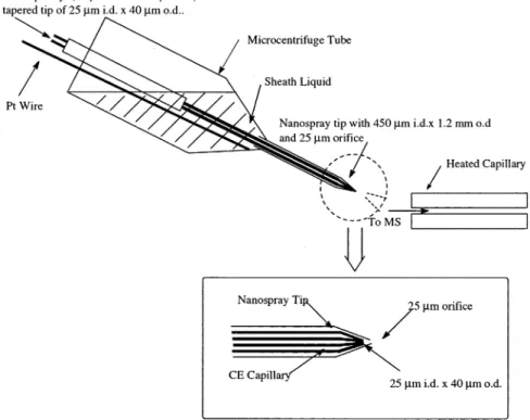
The Low-Flow CE/ESI-MS Interface. The orifice of a borosilicate nanospray tip (Protana Co., Odense, Denmark) was modified by removing the end of the tip using a ceramic cutter aided by visual inspection with a microscope. The tip was connected to a liquid reservoir (a microcentrifuge tube) and used as a sprayer for ESI (Figure 1). In CE/MS operation, the makeup liquid was injected into the reservoir using a 500-µL syringe. The tapered CE capillary was then fully inserted into the nanospray tip. Electrical contact was achieved by inserting a platinum (Pt) wire into the liquid reservoir. On average, the makeup solution was replaced every 10 runs.
Running buffer was driven by electroosmotic flow (EOF) of the capillary. However, unlike conventional sheath liquid interface, makeup liquid was not delivered by a syringe pump. In an experiment to estimate the flow rate of the interface, two compounds of very similar ionization efficiency (coptisine and
berberine) were added separately to the running buffer and makeup liquid. The flow rate of the running buffer (electroosmotic flow) was ∼200 nL/min. Because the intensities of the two compounds were found to be similar, the flow rate of the makeup liquid was estimated to be∼200 nL/min. Consequently, the total flow rate of the interface was∼400 nL/min.
CE/ESI-MS Analysis of Phenols. The separation buffer was 20 mM CHES in aqueous solution. The pH of the solution was adjusted to 10.0 with ammonia. Before each run, the capillary was flushed with the separation buffer and equilibrated for 15 min. The makeup liquid IPA/H2O/NH4OH (80/20/0.5, v/v/v) was placed into the liquid reservoir (volume, 500 µL). The 40 ppm phenolic mixture was hydrodynamically injected into the capillary using 15 mbar pressure differential for a duration of 15 s. The injection volume was calculated to be∼5 nL. CE/ESI-MS separa-tions were achieved by applying 20 kV and -2 kV to the injection end of the capillary and the liquid reservoir, respectively. The sprayer was positioned at a distance of∼2 mm from the orifice of the heated capillary.
LVSS CZE/ESI-MS Analysis of Phenols. Before sample injection, the CE running buffer (100 µL) was injected into the reservoir (microcentrifuge tube). The 40 ppb phenolic compounds, dissolved in 1 mL water with addition of 1 µL of 1 M NaOH, were hydrodynamically injected using a 30 mbar pressure differential for a duration of 30 min. The injection volume was∼1060 nL. Electrostacking was achieved by applying -20 kV to the capillary. The duration of the stacking process was determined by the current readout of the high-voltage supply. The stacking process was stopped when the current dropped to∼98% of the initial value. After stacking, the tip was moved closer to the MS orifice, and the remaining buffer in the reservoir was removed by the vacuum of the mass spectrometer. Makeup liquid was then injected into the reservoir prior to CE/MS analysis.
Figure 1. Schematic representation of the low-flow sheath liquid CE/ESI-MS interface.
Downloaded by NATIONAL TAIWAN UNIV on July 31, 2009
MEKC/ESI-MS Analysis of Triazines. The MEKC running buffers contained 20 mM ammonium acetate and 25 mM SDS in aqueous solution. The pH of the solution was adjusted to 7.0 with ammonia. The triazine mixture (20 ppm) was hydrodynamically injected into the capillary using a 15 mbar pressure differential for a duration of 10 s. The makeup liquid consisted of methanol, water, and acetic acid (70/30/1, v/v/v). The mass spectrometer was operated in positive ion mode and the data were collected in SIM mode.
Safety Considerations. Triazines and phenols are hazardous to human heath. The CE high voltage should be used with caution. RESULTS AND DISCUSSION
Dimensions of the Sprayer and the Cathode End of the Separation Capillary. In a conventional sheath liquid interface, the flow rate of sheath liquid is in the range of several microliters/ minute. This flow rate imparts a considerable dilution of the sample bands, since the flow rate of CE is in the range of several hundred nanoliters/minute. The use of such a high flow rate in a conventional sheath liquid interface is most likely due to the relatively large dimension of the sprayer used (for example, the orifice of the sheath tube is∼400 µm). It has been shown that the size of the orifice determines the optimal flow rate of the interface.31 In general, decreasing the size of the orifice also reduces the optimum flow rate. A tip with an orifice of∼25 µm was chosen for the interface used. For a 25-µm tip, optimum sensitivity can be obtained if the flow rate is above 200 nL/min.32 For the interface used, the flow rate was measured to be∼400 nL/min. This flow rate is higher than 200 nL/min and is about twice the EOF of a 50-µm-i.d. capillary, and as can be expected, sample dilution was minimized. It has been shown that a tip with a smaller orifice leads to increased ionization and ion-transfer efficiency, as compared to ESI conducted using a tip of larger orifice.33,34Because the orifice of the tip used was considerably smaller than that found with conventional sheath liquid interfaces, the sensitivity gain was expected to exceed the factor predicted from sample concentration alone. Although tips of even smaller inside diameter would improve sensitivity, an orifice diameter of <10 µm is not recommended, since it can easily become blocked by particles. Moreover, the flow rate of the separation capillary may be higher than the flow rate of a 10-µm tip, causing sample to accumulate inside the tip and resolution to degrade.
In the interface presented, the separation capillary was inserted to the very end of the sprayer in order to minimize dead volume (the volume between the tip of CE capillary and the orifice of the sprayer). To accommodate this design, one end of the separation capillary was tapered down to∼40-µm o.d..
Occasionally, during injection of the solution into the interface, air bubbles were observed in the sprayer. To remove air bubbles, the tip was moved closer (from 2 mm to∼0.5-1 mm) to the heated capillary orifice to use the vacuum of the mass spectrom-eter.
Performance of the Interface in CZE/ESI-MS. To evaluate the performance of the low-flow interface, a mixture of phenolic compounds was hydrodynamically injected into the capillary using (31) Wilm, M. S.; Mann, M. Int. J. Mass Spectrom. Ion Processes 1994, 136,
167-180.
(32) Gucek, M.; Vreeken, R. J.; Verheij, E. R. Rapid Commun. Mass Spectrom.
1999, 13, 612-619.
(33) Andren, P. E.; Emmet, M. R.; Caprioli, R. M. J. Am. Soc. Mass Spectrom.
1994, 5, 605-613.
(34) Wilm, M.; Mann, M. Anal. Chem. 1996, 68, 1-8.
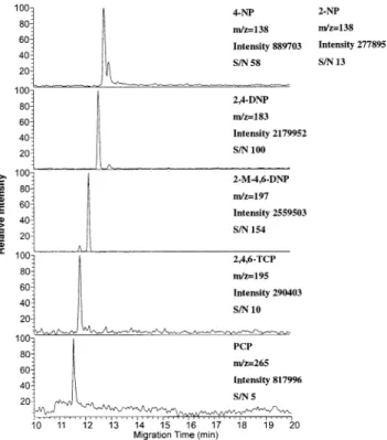
Figure 2. Mass electropherograms of a 40 ppm (dissolved in H2O) phenolic mixture using the low-flow CE/ESI-MS interface. The makeup liquid (IPA/H2O/NH4OH)80/20/0.5, v/v/v) was delivered at a flow rate of∼200 nL/min. The potential applied to the buffer reservoir was +20 kV, and the ESI voltage was set at-2 kV.
Figure 3. Mass electropherograms of a 40 ppm (dissolved in H2O) phenolic mixture using a conventional sheath liquid CE/ESI-MS interface. The sheath liquid (IPA/H2O/NH4OH)80/20/0.5, v/v/v) was delivered at a flow rate of 5µL/min. The potential applied to the buffer reservoir was+20 kV, and the ESI voltage was set at-4 kV.
Downloaded by NATIONAL TAIWAN UNIV on July 31, 2009
a 15 mbar pressure differential for a duration of 15 s. All compounds were resolved and detected in <15 min (Figure 2), and no electrical discharge occurred during CE/ESI-MS operation. Figure 3 shows the results obtained for the same phenolic solution using a conventional sheath liquid interface. A comparison of Figures 2 and 3 indicates that the low-flow interface exhibited significantly higher sensitivity than the conventional sheath liquid interface. On the basis of the average peak heights, the improve-ment was∼3-fold (275 931 ( 9.1% for low-flow interface and 75 386 ( 13.4% for conventional sheath liquid interface with N ) 3). As mentioned earlier, the improvement is most likely due to the low dilution factor and the use of a small-orifice tip.
LVSS CZE/ESI-MS. An important feature of this interface is that it allows in-probe focusing for on-line LVSS CZE/ESI-MS. The small volume between the separation capillary and the nanospray tip acts as a microreservoir for the running buffer. In this mode of operation, the sprayer was filled with running buffer before the stacking. After the stacking, the remaining buffer was removed and replaced with the makeup liquid prior to CE/MS operation. Figure 4 shows the results achieved with this interface. The improvement in sensitivity is illustrated by comparison to Figure 5, which displays the corresponding data obtained using normal hydrodynamic injection. An∼500-fold enhancement was achieved with this interface.
In conventional sheath liquid interface, the capillary tip should be retracted into the sheath-liquid tube during stacking. After the stacking, the capillary tip must be returned to its original position. This manual intervention represents a major difficulty in conven-tional LVSS operation. Using the low-flow interface, the position of the capillary tip remains constant during stacking and CE/MS
separation, making LVSS operation much easier than the con-ventional sheath liquid interface.
MEKC/ESI-MS. To demonstrate the feasibility of coupling MEKC with ESI-MS using SDS as the surfactant, a 20 ppm triazine mixture was hydrodynamically injected into the capillary using a
Figure 4. Mass electropherograms of a 40 ppb (dissolved in H2O) phenolic mixture using LVSS and the low-flow CE/ESI-MS interface. The makeup liquid (IPA/H2O/NH4OH)80/20/0.5, v/v/v) was delivered at a flow rate of∼200 nL/min. The potential applied to the buffer reservoir was+20 kV, and the ESI voltage was set at-2 kV.
Figure 5. Mass electropherograms of a 200 ppm (dissolved in running buffer) phenolic mixture using the low-flow CE/ESI-MS interface. The makeup liquid (IPA/H2O/NH4OH)80/20/0.5, v/v/v) was delivered at a flow rate of∼200 nL/min. The potential applied to the buffer reservoir was+20 kV, and the ESI voltage was set at-2 kV.
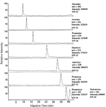
Figure 6. Mass electropherograms of triazine herbicides, 20 ppm (dissolved in H2O), using the low-flow interface. The makeup liquid (MeOH/H2O/CH3COOH)70/30/1, v/v/v) was delivered at a flow rate of∼200 nL/min. The potential applied to the buffer reservoir was+22 kV, and the ESI voltage was set at+2 kV.
Downloaded by NATIONAL TAIWAN UNIV on July 31, 2009
15 mbar pressure differential for a duration of 10 s. Eight triazine herbicides were fully separated and detected in the mass chro-matogram, as shown in Figure 6. The resolution of this approach appeared to be better than the data obtained using the technique of partial filling. Four (instead of eight) triazines were studied in a partial filling approach, and two of the triazines were not separated.29
It is known that SDS suppresses the signals of analytes. The effect of SDS on the signal of the analyte was studied. The results showed that the signal dropped to <30% when the concentration of SDS was increased to 35 mM. The signal was dropped to <10% if the concentration of SDS was increased to 55 mM. In this experiment, an SDS concentration of 25 mM was chosen because, with 25 mM SDS, the eight triazines could be baseline-resulted and the signals were∼30% higher than those at 35 mM SDS.
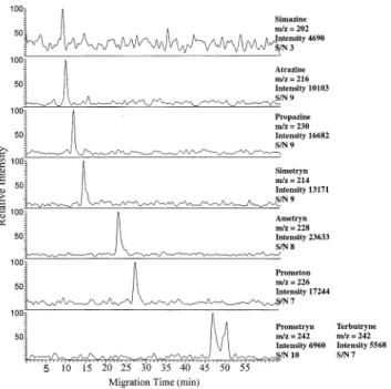
The quality of the data was also significantly better than that obtained by MEKC using a conventional sheath liquid interface. The mass chromatograms of triazines obtained with a conventional sheath liquid interface are shown in Figure 7. As can be seen,
significant increase in the sensitivity was observed in the low-flow interface (Figure 6), as compared to the conventional interface (Figure 7). On the basis of the average peak heights, the improvement was∼12-fold (230 337 ( 26.3% for low-flow interface and 18 891 ( 40.1% for conventional sheath liquid interface with
N )3).
The improved sensitivity can be explained by the higher salt tolerance and the superior ionization and sampling efficiency obtained using a nanospray tip. It has been reported that in nanospray, the higher surface charge density of the initial droplet results in early fissions without extensive evaporation, thereby decreasing the relative concentration of nonvolatile salts.35 There-fore, smaller and more highly charged droplets result not only in better electrospray ionization efficiency, but also resist ionization suppression when nonvolatile salts, such as SDS, are present in the CE running buffer. In addition to the better sensitivity, ion signals were also found to be much more stable than the conventional sheath liquid interface.23,24
CONCLUSIONS
A simple and versatile low-flow interface has been developed for CZE/MS, LVSS CZE/MS, and MEKC/MS operations. In this interface, the use of a small orifice electrospray tip substantially reduces the required makeup flow rate and thus decreases sample dilution. Because of low dilution and better ionization efficiency using a smaller tip, the sensitivity of this interface was found to be significantly better than a conventional sheath liquid interface. Since the position of the capillary tip remains stationary during stacking and CE/MS operation, LVSS is easier to perform than with a conventional sheath liquid interface. In addition, MEKC using 25 mM SDS can be easily coupled to ESI-MS using this low-flow interface. A more thorough investigation on the ability of this interface to accommodate other high salt conditions (e.g., phosphate, borate, etc.) awaits further study.
ACKNOWLEDGMENT
This work was supported by the National Research Council of the Republic of China.
Received for review September 2, 2002. Accepted November 26, 2002.
AC026098C
(35) Juraschek, R.; Dulcks, T.; Karas, M. J. Am. Soc. Mass Spectrom. 1999, 10, 300-308.
Figure 7. Mass electropherograms of triazine herbicides, 20 ppm (dissolved in H2O), using a conventional sheath liquid interface. The sheath liquid (MeOH/H2O/CH3COOH)70/30/1, v/v/v) was delivered at a flow rate of 5µL/min. The potential applied to the buffer reservoir was+24 kV, and the ESI voltage was set at+4 kV.
Downloaded by NATIONAL TAIWAN UNIV on July 31, 2009