國
立
交
通
大
學
電機學院 電機與控制學程
碩
士
論
文
應用緊密耦合記憶體之
Linux 內核效能最佳化
Optimizing Linux Kernel Performance with Tightly-Coupled Memory
研 究 生:林榮燦
指導教授:黃育綸 博士
應用緊密耦合記憶體之
Linux 內核效能最佳化
Optimizing Linux Kernel Performance with Tightly-Coupled Memory
研 究 生:林榮燦 Student:Jung-tsan Lin 指導教授:黃育綸 Advisor:Yu-Lun Huang 國 立 交 通 大 學
電機學院 電機與控制學程
碩 士 論 文 A ThesisSubmitted to College of Electrical and Computer Engineering National Chiao Tung University
in partial Fulfillment of the Requirements for the Degree of
Master of Science in
Electrical and Control Engineering July 2012
Hsinchu, Taiwan, Republic of China
應用緊密耦合記憶體之
Linux 內核效能最佳化
學生:林榮燦 指導教授:黃育綸 國立交通大學 電機學院 電機與控制學程碩士班 摘 要 緊密耦合記憶體 (Tightly-Coupled Memory,TCM) 比傳統記憶體結構 擁有高速存取與低耗電的優點。為此,TCM 最適合用於關鍵的常用程式和 資料結構。當前此領域的研究都是集中在非作業系統的嵌入式應用程式, 例如多媒體資料的處理,以提高整體效能。可能是由於 Linux 內核程式碼 和其資料結構是龐大且複雜的,因此沒有關於將作業系統內核函數程式放 到 TCM 之性能影響的討論。不當安排內核函數程式在 TCM 中會造成效 能降低。在本論文中,我們分析 TCM 的利用率和效能的影響,並把 Linux 內核函數程式根據 TCM 的容量進行分組。然後,我們選擇不同群組的 Linux 內核函數程式進行個別編譯,在系統執行期間將這些群組放入 TCM 並且不再置換。通過使用 lmbench 的實驗,我們找到把 exec() 或 schedule() 函數程式放置到 TCM 可以縮短本地端通信延遲 13%-14%。Optimizing Linux Kernel Performance with Tightly-Coupled Memory
student:Jung-tsan Lin Advisors:Dr. Yu-Lun Huang
Degree Program of Electrical and Computer Engineering
National Chiao Tung University
Abstract
TCM (Tightly-Coupled Memory) is advantaged of high-speed data access with lower power consumption than the traditional memory architecture. As such, TCM is a best fit to hold mission critical routines and data structures. Prior research of this area has emphasized on how TCM can be applied to non-OS embedded applications, like media streaming, to improve the overall performance. Possibly due to large and complicated Linux kernel code base and its data structures, there is no discussion regarding the performance impact when placing OS kernel functions into TCM. An improper arrangement of kernel functions in TCM can contrarily downgrade the performance. In this paper, we analyze the utilization and performance impact of TCM, and classify Linux kernel functions into groups per the TCM capacity. Then, we select different groups of Linux kernel functions at the compiling time and place these function groups into TCM without swapping them out during execution. By conducting the experiments with lmbench, we find that placing exec() or schedule() into TCM can reduce the local communication latency by a factor of 13% - 14%.
誌 謝
首先要由衷感謝指導教授 黃育綸老師在我碩士學習期間總是熱心而 不厭倦的指導我如何做研究,讓我得以順利的完成本論文; 再來要感謝家人 在我求學的日子里,給予我最大的支持,讓在學習路途上不會因為挫折而 放棄。 本篇論文謹獻給我的指導教授、我的家人以及在求學路上幫助我、鼓 勵我的長輩和朋友們,與您們一起分享這份喜悅。
Contents
摘要 i
Abstract ii
誌謝 iii
Contents iv
List of Figures vii
List of Tables xii
Chapter 1 Introduction 1
1.1 Tightly-coupled memory (TCM) 1
1.2 Motivation 3
1.3 Synopsis 4
Chapter 2 Related work 5
2.1 Data TCM allocation scheme 5
2.2 Instruction TCM allocation scheme 6 2.3 Both of instruction and data TCM allocation scheme 7 2.4 The analysis of instruction code 7
Chapter 3 The performance evaluation 9
3.1 Hardware architecture 9
3.2 Definition and analysis 13
3.3 Examples 15
Chapter 4 Kernel classification 21
4.1 Process-intensive 21 4.1.1 Process creation 21 4.1.2 Process termination 22 4.1.3 Process scheduling 22 4.1.4 Context switching 22 4.2 Memory-intensive 23
4.2.2 Virtual memory allocator 25
4.2.3 Buddy system 25
4.2.4 Slab system 27
4.2.5 Page fault operation 29
4.2.6 Physical page reclamation 29
4.3 I/O-intensive 30
4.3.1 Interrupts and interrupt handlers 30
4.3.2 Virtual file system (VFS) 31
4.3.3 Timer controller 32 Chapter 5 Experiments 33 5.1 Environments 33 5.1.1 Hardware requirement 33 5.1.2 Software requirement 33 5.1.3 Experimental environment 34 5.2 Experiments 40
5.2.1 Exp #1: Process benchmark 43
5.2.2 Exp #2: Context switching benchmark 50 5.2.3 Exp #3: File & VM system benchmark 54 5.2.4 Exp #4: Local communication benchmark 60
5.3 Analysis 63
Chapter 6 Conclusion 69
List of Figures
Figure 1.1 Memory diagram 2
Figure 1.2 TCM memory address space 2
Figure 1.3 ARM processer market share rate 4
Figure 2.1 The kernel-storage model 8
Figure 3.1 MMU checking and translation mechanism 10 Figure 3.2 Original embedded system architecture 11 Figure 3.3 Proposed embedded system architecture 12 Figure 3.4 The icache and main memory layout with TCM for case 3a 18 Figure 3.5 The icache and main memory layout with TCM for case 3b 19 Figure 3.6 TCM capacity vs. function size trend 20 Figure 4.1 Memory address space for 32-bit CPU 23
Figure 4.2 Page tables 25
Figure 4.3 The array of a buddy system 26 Figure 4.4 Layout of the slab allocator 28 Figure 4.5 The flow of write() system call 32
Figure 5.1 Experimental environment 34
Figure 5.2 Samba server setting in the /etc/samba/smb.conf 35 Figure 5.3 The setting of Linux kernel configuration 38 Figure 5.4 The simple system call latency 44
Figure 5.5 The simple I/O latency 45
Figure 5.6 File status access latency 45
Figure 5.7 File open and close latency 46 Figure 5.8 File descriptor select latency 46 Figure 5.9 Signal installation latency 47
Figure 5.10 Signal handling latency 48
Figure 5.11 Fork process running latency 48 Figure 5.12 Exec process running latency 49
Figure 5.13 Shell process running latency 49 Figure 5.14 2p/0K context switching latency 51 Figure 5.15 2p/16K context switching latency 51 Figure 5.16 2p/64K context switching latency 52 Figure 5.17 8p/16K context switching latency 52 Figure 5.18 8p/64K context switching latency 53 Figure 5.19 16p/16K context switching latency 54 Figure 5.20 16p/64K context switching latency 54
Figure 5.21 0K file creation latency 55
Figure 5.22 0K file deletion latency 56
Figure 5.23 10K file creation latency 56
Figure 5.24 10K file deletion latency 57
Figure 5.25 Memory mapping latency 57
Figure 5.26 Fault protection latency 58
Figure 5.27 Page fault latency 58
Figure 5.28 100 file descriptors selection latency 59
Figure 5.29 Pipe latency 61
Figure 5.30 AF UNIX latency 61
Figure 5.31 UDP latency 62
Figure 5.32 TCP latency 62
List of Tables
Table 3.1 An example of function allocation 15
Table 5.1 Required files 37
Table 5.2 The lmbench basic system parameters 41 Table 5.3 The lmbench process parameters 44 Table 5.4 The lmbench context switching parameters 50 Table 5.5 The lmbench file & VM system latency parameters 55 Table 5.6 The lmbench local communication latency parameters 60 Table 5.7 Summary of lmbench process latency 64 Table 5.8 Summary of lmbench context switching latency 65 Table 5.9 Summary of lmbench file & VM system latency 66 Table 5.10 Summary of lmbench local communication latency 67
Chapter 1
Introduction
This chapter introduces a novel memory technology, tightly-coupled memory (TCM), providing high speed data access within a central processing unit. After a brief introduction to TCM, we describe the pros and cons of the novel memory technology, our motivation, and the synopsis of the thesis.
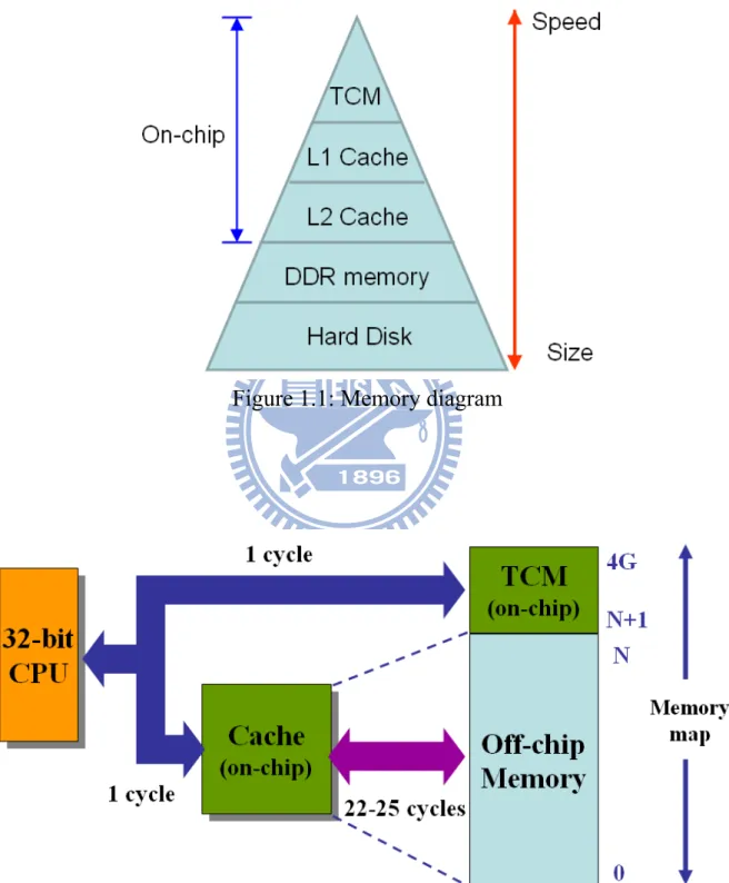
1.1 Tightly-coupled memory
TCM, a high speed SRAM (Static Random Access Memory) is designed in an embedded processor like Level 1 cache as shown in Figure 1.1. TCM memory address space is included within 4 GB (Giga-Bytes) memory map of a 32-bit CPU (Central Processing Unit). TCM can be used to store frequently accessed data or instructions. The advantage of TCM is that a CPU can access required instructions or data in one clock cycle to reduce the access latency around 25 cycles caused by an off-chip main memory.
However, in order to achieve the same clock frequency as a CPU, the size of TCM is limited like a cache. The size of TCM is usually between 4 KB to 32 KB (Kilo-Bytes). The limitation might lead the performance down if the size of an application program is too large to fit into TCM. For example, the size of a program containing a function foo_a and its subfunction foo_b is 100 KB. Since the program size is larger than TCM size, the function foo_a is located in TCM and its subfunction foo_b is located in the off-chip main memory. Trivially, accessing function foo_a can be done in one clock cycle, but more clock cycles are required due to the accessing to foo_b in the main memory. The total execution time might be greater than the processor without using TCM. TCM
has a disadvantage of limited size, so how we arrange appropriate code from huge codes such as Linux kernel into TCM is very important.
Figure 1.1: Memory diagram
Although a cache and a TCM are both made up of SRAM cells, the operations are different. A cache is designed to hold the instructions and data from recently accessed memory locations to improve performance of general purpose processors. A cache contains tag RAM and data RAM. The tag RAM is mapped against the external memory address. If the instruction or data exists in the cache, the processor fetches them in one clock cycle to reduce the accesses to the main memory. On the other hand, TCM only contains data RAM and is located as a part of the main memory address map. Avoiding a check of the tag RAM can reduce the total execution time. According to the characteristics of cache and TCM, many cache or TCM studies were proposed to improve the system performance. There is a detailed comparison between cache and TCM in [1], and the result shows that TCM has 40% lower power consumption and 34% smaller area than a cache memory with the same capacity.
1.2 Motivation
With the progress of science and technology, an embedded system becomes an integral part of human life. To handle a growing number of computing operations, instead of developing faster CPUs, we also consider the improvent of performance when running programs with the existing CPUs.
Under the existing CPU architectures, we can find out that ARM processers design TCMs and MIPS introduces Scratchpad memory to improve the system performance. The memory is located within a processer, its priority is higher than caches, and provides high speed performance without accessing system bus. According to the statistics shown in Figure 1.3 (data source: ARM official website in 2011), for mobile computing, ARM’s processer market share will be greater than 50% by 2015, especially 85% for Media Tablets, and >30% for Mobile PC. So we consider ARM processer as our research platform.
Figure 1.3: ARM processer market share rate
(data source: ARM official website in 2011)
In general, the TCM memory is used by non-OS software, because it is easy to be controlled by a designer. Regarding Linux, Android OS, and so on, the code structure is very complex and code size is much more than TCM memory size. Our purpose is to research how to select proper kernel functions from a common Linux kernel into the limited TCM memory space to improve the overall performance.
1.3 Synopsis
The remainder of this paper is organized as follows. Chapter 2 discusses related work. Chapter 3 describes TCM performance evaluation. Chapter 4 proposes kernel classification. Chapter 5 explains the experimental environment and presents the results. Finally, Chapter 6 is the conclusion of the thesis.
Chapter 2
Related work
Existing work on the TCM utilization can be classified into three categories: (1) apply to a data memory only; (2) apply to an instruction memory only; or (3) apply to both of an instruction memory and a data memory. Base on above categories, they can be further divided into two classes: one is static allocation and the other is dynamic allocation. The difference is whether the contents of TCM are changed during the program execution or not. The purpose of TCM memory utilization is to improve the performance of program execution and reduce the electrical energy.
2.1 Data TCM allocation scheme
For static data TCM, the optimization methods for data memory are presented in [3, 4, 5, 6, 7, 8]. In most of researches, test data patterns were analyzed to find frequently accessed variables and constants. For example, P. Panda et al. in [3] propose some partitioning strategies: (1) assign scalars to SRAM and arrays to DRAM; (2) array with size larger than SRAM is placed in DRAM; (3) arrays with highest intersecting life times are placed in SRAM; (4) arrays with highest variable access count are placed in SRAM.
For dynamic data TCM, a dynamic management method of data memory is presented in [9]. Ning Deng et al. propose a memory address random sampling scheme to identify the frequently accessed region during execution time. The proposed software handler can deal with TCM allocation.
[3, 4, 5, 6, 9] discuss the allocation of both global data and stack variables to TCM, while [7] and [8] can only allocate global data to TCM.
2.2 Instruction TCM allocation scheme
For static instruction TCM, an example is described in [10]. F. Angiolin et al.
propose a patching tool to do binary code relocation. First of all, the source code of application is compiled to binary one. Then, the binary image runs on target platform to collect the statistics of an execution trace. Those statistics and the application-independent information such as the size of the target TCM are analyzed by the TCM analysis algorithm. Eventually, some optimal code segments are found and passed to the patching tool. This tool modifies the original binary image of application to insert jump instructions, adjust some critical instructions, and move code to different address regions. The experiment proves that a post-compilation approach improves application optimization without compiling source code of application again.
For dynamic instruction TCM, the optimization methods for instruction memory are presented in [11, 12, 13]. For example, M. Kandemir et al. in [11] propose an algorithm to decide frequently accessed instructions into TCM. The algorithm has four steps: (1) divide the code into regions; (2) assign timestamp for each region; (3) select the instructions copied to and evicted from TCM according to code profiling; (4) decide if instructions are swapped actually according to cost analysis. The result of experiment shows the execution time has a great improvement.
The common characteristic of the above mothods is that the application code needs to be profiling in advance. This means that the application binrary or source code must be modified one or more times.
2.3 Both of instruction and data TCM allocation scheme
The representative research of instruction and data TCM static allocation is [14]. An algorithm analyzes the application and selects best program and data code into limited size of TCM to save the maximum of electrical energy. S. Steinke et al. define two memory object types; one is program memory object which is a function or a basic block; the other is data memory object which is a variable. Program memory objects are put into instruction TCM while data memory objects are put into data TCM. Based on the limited size of TCM, S. Steinke et al. define the related equations and apply the method of [15] to gain the cost for the use of a TCM memory. According to analysis of cost, the best set of memory objects can be found. Finally, S. Steinke et al. compare the TCM versus Cache performance in the same memory size. The result shows TCM saves about 22% of electrical energy.
2.4 The analysis of instruction code
In order to select the proper codes into an instruction TCM, an appropriate analysis method is necessary. Most of prior researches focus on loop blocks analysis of the trace of an application program. In [16], He Yi et al. built a kernel-storage model shown in Figure 2.1 to analyze the hot spot loop blocks of key instructions in stream programs. The left of Figure 2.1 is a kernel contains two loop functions. LOOP1 function has L1 instructions and is executed C1 times, while LOOP2 function has L2 instructions and is executed C2 times. Besides, LOOP1 includes LOOP2. The right of Figure 2.1 is an instruction TCM and its depth is L.
instruction TCM. If L1 > L ≥ L2, it means only LOOP2 function can be placed in the instruction TCM. Because LOOP1 includes LOOP2, He Yi et al. define that LOOP2 is the Hot Code of LOOP1.
Figure 2.1 The kernel-storage model (data source: [16])
Based on the analysis, He Yi et al. define Kernel Hot Code for each stream media application program. The Kernel Hot code is placed into an instruction TCM when running the specific program.
Loop analysis, however, has several disadvantages: (1) the system structure and relationship of loop functions should be very complex; (2) different applications need to design a specific system structure. Besides, all prior researches of TCM memory focus on a non-OS embedded application program, because it is easy to be analyzed. Regarding Linux, Android OS, and so on, the code structure is very complex and the size of the code is much more than the size of TCM memory. We purpose a method to select proper kernel codes into the limited TCM memory space to improve the performance.
Chapter 3
The performance evaluation
All prior researches of TCM memory focus on a non-OS embedded application program, because it is easy to be analyzed. Regarding Linux, Android OS, and so on, the code structure is very complex and code size is much more than the size of TCM memory. If use of TCM is not good, the performance is down. So an analysis model is necessary. In this chapter, we describe the architecture of ARM processor with TCM, the proposed analysis model, and a comparison analysis when kernel uses TCM or not.
3.1 Hardware architecture
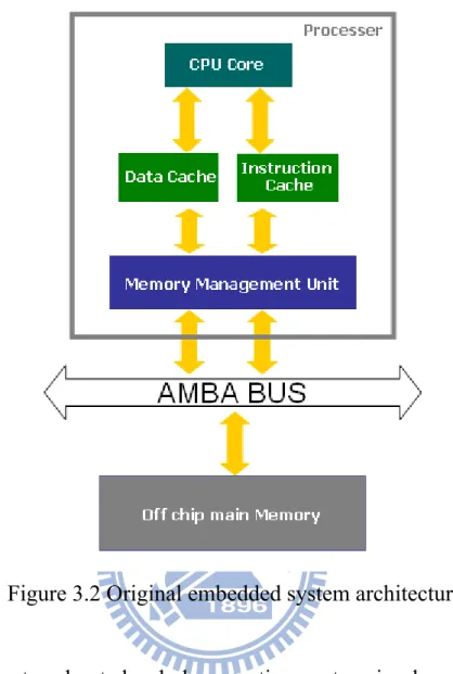
Under normal circumstances, an embedded operation system is designed to run at cache memory due to performance reason. There is a basic ARM embedded system architecture shown in Figure 3.2. We simplify the description of the embedded system and discuss the minimum requirement of running an operation system, so the architecture only contains an ARM processer, a system bus, and a main memory.
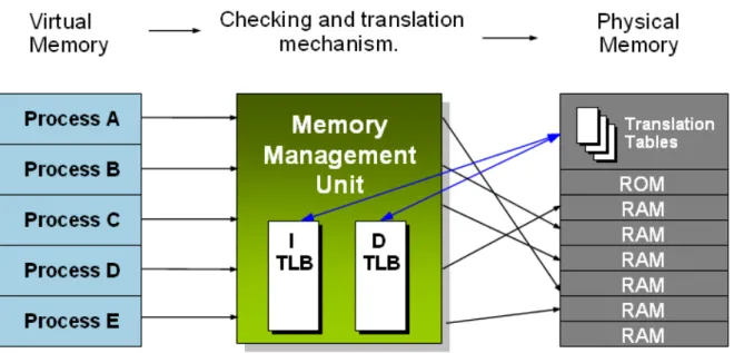
Generally, an ARM processer has a central processing unit (CPU), an Instruction Cache, a Data Cache, and a memory management unit (MMU) inside. The CPU core handles the execution of instructions. The Instruction Cache and Data Cache are designed to have the same clock frequency as a CPU core and store a few used instructions and data recently. Compared with the off chip main memory, the Instruction Cache reduces the fetch instruction latency while the Data Cache reduces load or store data latency. However, a cache memory has a disadvantage of high cost so that a cache memory is not suitable for large size. A MMU shown in Figure 3.1 controls the mapping between the physical address
memory space and the virtual address memory space for general operation systems. A general operation system has a multi-user and multi-process kernel. Each user program has its own address memory space and other unrelated programs can not see and access it. This address space is referred to as virtual address. In fact, the kernel and all programs are placed in the same off chip main memory. This address space is referred to as physical address. A MMU is an important bridge between them.
Figure 3.1 MMU checking and translation mechanism
A main memory is enough to store whole embedded operation system including the kernel, applications, and file system named RAM disk … and so on. But the main memory has long access latency. An Advanced Microcontroller Bus Architecture (AMBA) bus is an on-chip communications standard defined by ARM Limited.
Figure 3.2 Original embedded system architecture
After a system booted, whole operation system is placed in an off chip main memory. When the processer executes a process or task, the CPU fetches wanted instructions from the Instruction Cache and loads wanted data from the Data Cache first. If the caches don’t store these instructions and data, the CPU fetches them from external main memory through system bus and stores a copy in the Instruction Cache and the Data Cache. If the Cahe is full, the unused instructions and data recently are replaced by new ones.
Because the access latency of an off chip main memory is much greater than a cache memory, it is important issue to reduce the number of times that a CPU accesses an off chip main memory.
Figure 3.3 Proposed embedded system architecture
In this paper, we propose a new architecture shown in Figure 3.3. We add an Instruction TCM used in the embedded system. According to the proposed method, we choose the proper kernel codes in the compile phase and then put them into the Instruction TCM when the operation system power on. The instructions in the Instruction TCM are always alive and are never replaced in the run-time phase.
When the processer executes a process or task, the CPU fetches wanted instructions from the Instruction TCM directly if the TCM has them. Then the CPU fetches other wanted instructions from the Instruction Cache and loads wanted data from the Data Cache first. If the caches don’t store these
instructions and data, the CPU fetches them from external main memory through system bus and stores a copy in the Instruction Cache and the Data Cache. If most of the instructions of a process are placed in the TCM, the proposed architecture can reduce the number of times that a CPU accesses an off chip main memory. And then the performance of an operation system can improve.
3.2 Definition and analysis
This section describes our analysis model. The total kernel codes have
n
instructions; some of them have
x
instructions put in a TCM memory and the others havey
instructions placed in a cache memory. A formula can be defined as follows.Eq (1)
If
x
= 0, it means running an operation system doesn’t use a TCM memory. Otherwise, Ify
= 0, it means running an operation system doesn’t use a cache memory. In this paper, we focus on performance enhancement using current cache memory architecture of an operation system. So we don’t considery
= 0.If
x
= 0, an operation system always runs at a cache memory. A formula for total execution time of a task or process can be defined as follows.T
no−tcm=
y
×
t
c+
b
×
t
m Eq (2)Where
y
: Numbers of instructions in a cache memory.c
t
: The execution time of one instruction in a cache memory.m
t
: The execution time that a processer copies the instructions of one cache liney
x
from an off chip main memory to a cache memory when the CPU can not fetch the required instructions from a TCM and a cache memory.
b
: The number of times that a processer copies the instructions of one cache line from an off chip main memory to a cache memory after the CPU completed a task or process of an operation system.If
x
≠
0, an operation system runs at a TCM memory and a cache memory. A formula for total execution time of a task or process can be defined as follows. m c t tcm=
x
×
t
+
y
×
t
+
b
×
t
T
Eq (3) Wherex
: Numbers of instructions in a TCM memory.t
t
: The execution time of one instruction in a TCM memory.y
: Numbers of instructions in a cache memory.c
t
: The execution time of one instruction in a cache memory.m
t
: The execution time that a processer copies the instructions of one cache line from an off chip main memory to a cache memory when the CPU can not fetch the required instructions from a TCM and a cache memory.b
: The number of times that a processer copies the instructions of one cache line from an off chip main memory to a cache memory after the CPU completed a task or process of an operation system.In this paper, we adopt a static TCM allocation scheme. But, the TCM memory capacity of a processer is limited. For this reason, the size constraint is defined as follows.
TCM
of
size
≤
x
Eq (4)When
T
tcm≤ T
no−tcmunder the condition of Eq (4), we can improve theperformace of an operation system. If the select instructions are improper, it is possible to cause
T
tcm is greater thanT
no−tcm.3.3 Examples
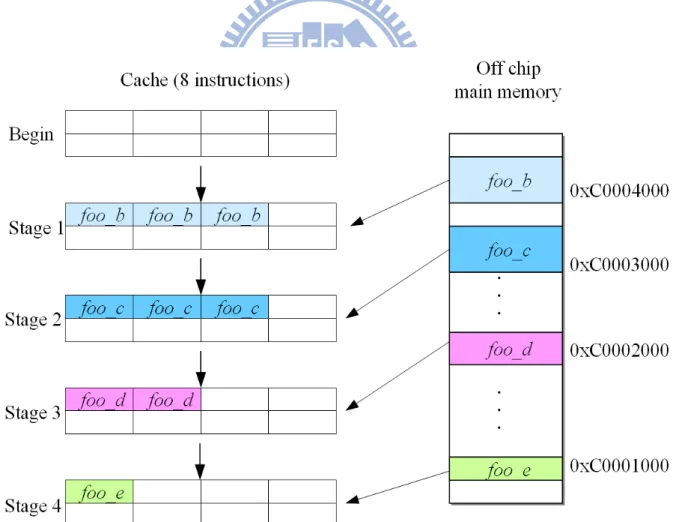
We assume that a CPU clock and a system bus clock use the same frequency. The CPU which accesses a TCM and a cache needs to spend one clock cycle. And the CPU which accesses a main memory on the system bus needs to spend 25 clock cycles. The size of a cache or a TCM is 8 instructions. A Linux executes the function 10 times after the Linux system powered on. In this section, we discuss the relationship between TCM capacity and Function size. They contain Function size ≤ TCM, TCM < Function size ≤ Instruction cache + TCM, and Instruction cache + TCM < Function size.
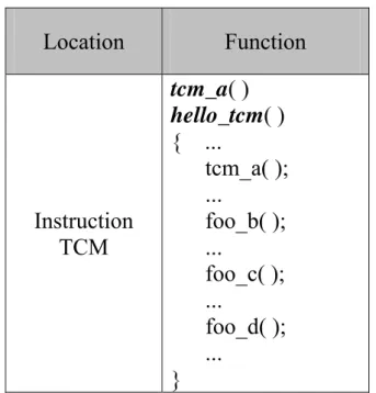
Table 3.1 An example of function allocation Location Function Instruction TCM tcm_a( ) hello_tcm( ) { ... tcm_a( ); ... foo_b( ); ... foo_c( ); ... foo_d( ); ... }
Off chip main memory foo_b( ) foo_c( ) foo_d( ) foo_e( )
Case 1: Function size ≤ TCM
There is one function called hello_tcm. Function hello_tcm contains three subfunctions, tcm_a, foo_b, foo_c, foo_d, and foo_e. The size of the function is 6 instructions.
Without TCM: whole function is copied to the cache one time and is
executed ten times in the cache, so
T
no−tcm= 6x10x1 + 1x25 = 85 cyclesaccording to Eq(2).
With TCM: whole function has been placed in the TCM and can be
executed ten times directly, so
T
tcm= 6x10x1 + 0x1 + 0x25 = 60 cyclesaccording to Eq(3).
We can get
T
tcm≤ T
no−tcm, so with TCM is better than without TCM.Case 2: TCM < Function size ≤ Instruction cache + TCM
There is one function called hello_tcm. Function hello_tcm contains three subfunctions, tcm_a, foo_b, foo_c, foo_d, and foo_e. The size of the function is 16 instructions.
Without TCM: the value of
b
is 20 (= 8 16 x10), so tcm no−
T
= 16x10x1+ 20x25 = 660 cycles according to Eq(2).
remainder is copied to the cache from the main memory one time and is executed ten times, so
T
tcm= 8x10x1 + 8x10x1 + 1x25 = 185 cyclesaccording to Eq(3).
We can get
T
tcm≤ T
no−tcm, so with TCM is better than without TCM.Case 3a: Instruction cache + TCM < Function size & continuous subroutines
There is one function called hello_tcm as shown in Table 3.1. Function
hello_tcm contains three subfunctions, tcm_a, foo_b, foo_c, foo_d, and foo_e.
The size of whole function is 17 instructions. hello_tcm and tcm_a are 8 instructions while foo_b, foo_c, foo_d, and foo_e are 9 instructions.
Without TCM: the value of
b
is 30 (= 8 17 x10), so tcm no−
T
= 17x10x1+ 30x25 = 920 cycles according to Eq(2).
With TCM: hello_tcm and tcm_a has been placed in the TCM. If foo_b,
foo_c, foo_d, and foo_e are contiguous in the main memory, the CPU
needs to access the main memory two times when running whole function every time, so
T
tcm= 8x10x1 + 9x10x1 + 8
9 x10x25 = 670 cycles
according to Eq(3).
We can get
T
tcm≤ T
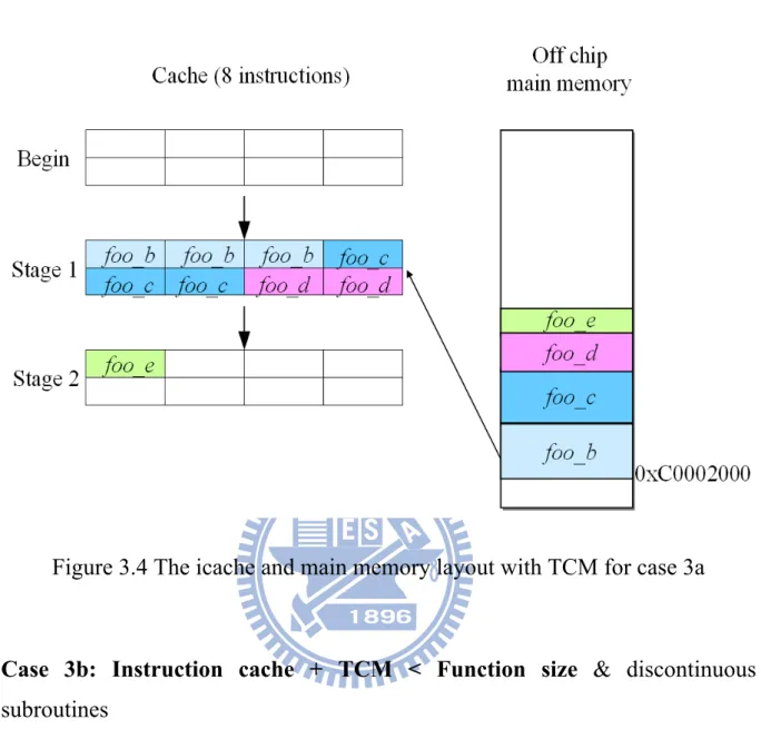
no−tcm, so with TCM is better than without TCM. Weassume that foo_b() has 3 instructions, foo_c() has 3 instructions, foo_d() has 2 instructions, and foo_e() has one instruction. Since the CPU fetches a cache line (8 instructions) in one time, the CPU spent 2 (=
8
9 ) times to copy these
subfunctions from the off chip main memory to the cache. Figure 3.4 shows the instruction cache and main memory layout with TCM for cache 3a.
Figure 3.4 The icache and main memory layout with TCM for case 3a
Case 3b: Instruction cache + TCM < Function size & discontinuous
subroutines
There is one function called hello_tcm as shown in Table 3.1. Function
hello_tcm contains three subfunctions, tcm_a, foo_b, foo_c, foo_d, and foo_e.
The size of whole function is 17 instructions. hello_tcm and tcm_a are 8 instructions while foo_b, foo_c, foo_d, and foo_e are 9 instructions.
Without TCM: the value of
b
is 30 (= 8 17 x10), so tcm no−
T
= 17x10x1+ 30x25 = 920 cycles according to Eq(2).
With TCM: hello_tcm and tcm_a has been placed in the TCM. If foo_b,
to access the main memory three times when running whole function every time, so
T
tcm= 8x10x1 + 9x10x1 + 4x10x25 = 1170 cycles according toEq(3).
We can get
T
tcm> T
no−tcm, so with TCM is worse than without TCM. Weassume that foo_b() has 3 instructions, foo_c() has 3 instructions, foo_d() has 2 instructions, and foo_e() has one instruction. The parent function, hello_tcm(), is distant from off chip main memory. The subfunctions may be discontiguous because the compiler may think these subfunctions have no relationship. Since these subfunctions are discontiguous, the CPU spent 4 times to copy these subfunctions from the off chip main memory to the cache. Figure 3.5 shows the instruction cache and main memory layout with TCM for cache 3b.
According to our analysis model, we get a TCM capacity vs. function size trend as shown in Figure 3.6. The trend shows that if improper functions are placed into the TCM, the overall system performance may be downgraded.
0 50 100 150 200 250 300 1 2 3 4 5 6 7 8 9 1011 121314 1516 171819 202122 232425 262728 2930 Function size Ex ec uti on tim e TCM (best case) TCM (worst case) Cache only
Figure 3.6 TCM capacity vs. function size trend
It is very important to select the proper kernel codes and place them into the TCM. However, the kernel is too huge to fit all into the TCM, so we classify the OS kernel according to characteristics of the kernel functions. The proposed kernel classification is detailed in Chapter 4.
Case 1
Case 2
Case 3b
Chapter 4
Kernel classification
Generally, a kernel image is too huge to be placed into TCM, so we must divide kernel to meet the limitation of TCM memory space. Furthermore, according to the proposed model in Chapter 3, to select appropriate instructions into TCM is very important, otherwise, the performance is down. In this chapter, we devide and classify kernel to process intensive, memory-intensive, and I/O-intensive according to the characteristics of kernel functions.
4.1 Process intensive
A process is an executing program in general operating systems. However, besides the executing program code, a process also includes some resources such as processor state, an address space, kernel data, and one or more threads. The most important part of process-intensive kernel functions is a process management. The process management involves process creation, process termination, and process scheduleing.
4.1.1 Process creation
A kernel uses fork() and exec() functions to complete a process creation. First of all, the fork() function creates a child process copied from the current process. And then exec() function loads the program code into the address space and execute it with the child process resources. In a Linux kernel, the major functions used to create processes are do_fork(), do_execve(), and so on.
4.1.2 Process termination
A process must die eventually. When a process terminates, the kernel releases the resources of the process and notifies the parent process. For example, a process completes its job to terminate, or a sub-function terminates and returns its main function in a program. The process calls the exit() system call to do that. Sometimes, a process terminates involuntarily when the process receives an exception such as ctrl+C signal from a keyboard. In a Linux kernel, the major function used to terminate processes is do_exit().
4.1.3 Process scheduling
The process scheduler is designed to select which process can be executed by the processer. The process scheduler manages the runnable processes to share the finite resource of processor time in the operation system. A good scheduler makes full use of system resources so that users think that multiple processes are executing simultaneously. An operation system with the process scheduler is called multitasking operating system such as Linux. The major function of the process scheduler is schedule() in a Linux kernel.
4.1.4 Context switching
A context switching function is responsible to switch from one runnable process to another. The context switching is one part of the process scheduler. It does two basic jobs: 1) to store the data of current process including stack information and the processor registers; 2) to change virtual memory mapping and the processor state from current process to the new process. In a Linux kernel, the major function of context switching is context_switch().
4.2 Memory-intensive
The most important part of memory-intensive kernel functions is a memory management. The virtual memory can be much larger than the physical memory in the operation system. As shown in Figure 4.1, each process has its own 4 GB address memory space and other unrelated processes can not see and access it. This address space is referred to as virtual memory address. In fact, these processes are placed in the same off chip main memory. This address space is referred to as physical memory address. The memory management system is responsible for managing process address spaces.
4.2.1 Page table operation
Although user application programs operate on a virtual memory, the processor operates them directly on a physical address. For this reason, when a user application program accesses a virtual memory address, it must first be translated into a physical address before the processor can deal with the request. In order to complete the translation, memory management unit (MMU) and page tables are necessary. A MMU is implemented in a processer. Page tables are placed in an off-chip main memory and store the mapping index between the virtual address and the physical address.
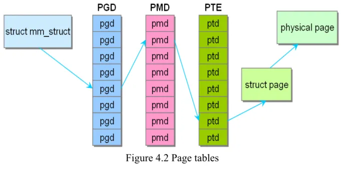
The page tables consist of three levels in a Linux. The multiple levels allow a small populated memory space to store a huge index map. If the page tables were designed as a single array, their size would be enormous. Three levels of page tables also can use on an architecture which does not support three levels in hardware. For example, the ARM processer uses a two-level page table for 4KB page size.
The top level page table is called page global directory (PGD). The PGD stores the entries of the second level directory. The second level page table is called page middle directory (PMD). PMD stores the entries of the final level page table. The final level page table is called page table entry (PTE). Page table entry stores the physical pages. In general, page table look-up is handled by hardware. Figure 4.2 shows a translation flow from a virtual address to corresponding physical address using page tables. Each process has its own page tables. In Linux kernel, the major function of kernel page table is paging_init().
Figure 4.2 Page tables
4.2.2 Virtual memory allocator
In a Linux kernel, the function of virtual memory allocator is referred to as
vmalloc(), and allocated memory is contiguous in a virtual address and not
necessarily contiguous in a physical RAM. That is, the virtual memory allocator can allocate noncontiguous physical memory space. For example, a user application program uses virtually contiguous memory space and never knows that physical memory space is contiguous or not.
4.2.3 Buddy system (physical page allocator)
When a kernel needs for memory allocation such as load a process, the kernel applies a buddy system minimum page mechanism to manage unused memory debris. In a buddy system, a page frame represents a group of contiguous minimum pages. The area of unused page is divided into ten species of block size. Respectively they are 1, 2, 4, 8, 16, 32, 64, 128, 256, and 512 contiguous minimum pages. Each minimum page of a Linux system is 4 KB. The buddy system uses a method called free_area[10] array as shown in Figure
4.3 to store the usage status of those page frames. The first page frame chain stores starting address of isolated idle minimum page, that is prevous and next page have been used. The second page frame chain stores starting address of first page in two contiguous minimum pages. The third page frame chain stores starting address of first page in four contiguous minimum pages. And so on.
Figure 4.3 The array of a buddy system
If there is a requirement of memory, the system is looking for the smallest block of sufficient size. For example, suppose that a process requires 15 pages, the system first checks whether the 16 pages frame chain has available free blocks or not. If not, then system looks for a 32 pages frame to the process. If the 32 pages frame chain has available free blocks, the system allocates 15 pages to the process and moves remaining 17 pages to 16 pages frame chain and one page frame chain. If the 32 pages frame chain still has no available free pages, the system searches free pages in next chain and makes a similar treatment.
After the process completed, it should release used page frame. Then the system attempts to combine these released pages with adjacent unused area to a single contiguous block, and stores starting address of new block into page frame chain. In a Linux kernel, the major functions of a buddy system are
alloc_pages(), alloc_page(), __alloc_pages(), __free_pages(), free_pages(), free_page(), and so on.
4.2.4 Slab system (allocates small memory blocks)
In a Linux 2.6 kernels, a slub allocator replaces the slab allocator. Although slub allocator and slab allocator are different algorithms, they are generally referred to as "slab allocator". Following the old name is to indicate the level of memory management mechanism. When kernel needs to allocate a small amount of memory like required memory of malloc function, a slab allocator is used and its allocated data is known as object. Slab object is stored in the page frame of buddy system, if we want to assign an object of size 32 bytes, slab requests a minimum page (4KB) from the buddy system, and then assign a slab allocator. And slab allocator preserves some bits to record layout information, and the remaining space is divided into objects of size 32 bytes. When the similar configuration request occurs, these empty objects can be used.
Figure 4.4 shows a slab structure. The top level is a cache chain. Each cache contains a list of slabs, which is a contiguous memory block (typically page). There are 3 kinds of slab below,
slabs_empty: all objects on a slab marked as free slabs_partial: a slab has both used and free objects slabs_ful: all objects on a slab marked as used
Figure 4.4 Layout of the slab allocator
Slab in the slabs_empty list is the main candidate for recycling, i.e the memory is returned to the operating system. In slab list, each slab is a contiguous memory block (one or more contiguous pages), which is divided into some objects. These objects are basic elements which are allocated and released from a specific cache.
The object is allocated and released from the slab, so a single slab can be moved between slab lists. For example, when all objects are used in a slab, the slab needs to be moved from slabs_partial list to slabs_full list. When an object in one slab of slabs_full list is released, this slab needs to be moved from slabs_full list to slabs_partial list. After all objects of this slab are released, this slab needs to be moved from slabs_partial list to slabs_empty list. The major
functions of a slab system are kmem_cache_create(), kmem_cache_alloc(),
kmem_cache_free(), kmem_cache_destroy(), kmem_cache_shrink() in a Linux
kernel.
4.2.5 Page fault operation (page table allocates physical memory pages)
We all know that each minimum page of a Linux operating system is 4 KB. When user executes some programs, the operating system loads a number of pages including the partial programs from storage device to main memory. When a program needs a page which is not in main memory and there is also no free page in main memory, the operating system takes currently unused page back to the storage device and then loads the required page into main memory. If there are some free pages in main memory, the operating system can copy the required page from storage device into a free page in main memory. Finally, the operating system modifies the mapping between virtual address and physical address for the required page. This operation is referred to as "Page Fault". In a Linux kernel, the major function is do_page_fault().
4.2.6 Physical page reclamation
A system eventually uses all available pages for various reasons. The operating system needs to select currently unused pages and then empties out them before physical main memory is exhausted. In order to reduce the amount of access storage device I/O, the operating system also uses the page cache. Page cache area is the kernel to access the data first. After the required data could not be found in Page cache, kernel finds it in storage device. All data that is first read from storage device is stored in the page cache. Continued access of operation causes page cache area is getting bigger. It eventually consumes all of
memory that can be used by operation system. Therefore, the least recently used data is moved out of page cache, and then limited memory space can store more frequently access data.
How does operation system select currently unused page? General operation system uses LRU (Least Recently Used) lists to store age information of each page so that the least recently used page can be easily scanned for replacement. The LRU in operation system consists of two lists which are the active list and the inactive list. The active list contains all working processes and the inactive list contains reclaim candidates. All the process pages and file pages are managed in two LRU lists by page replacement policy. In a Linux, the major functions of page reclamation are add_to_page_cache(), lru_cache_add(),
activate page(), and so on.
4.3 I/O-intensive
The I/O-instensive kernel functions contain all peripherals of an operation system such as interrupt controllers, file systems, timer controllers, Ethernet controllers, SD card controllers, NAND flash controllers, and so on. In this paper, we only select some of all device controllers to do experiments.
4.3.1 Interrupts and interrupt handlers
Interrupts allow hardware devices to communicate with the processor actively. At any time, a hardware device generates an interrupt electronic signal into the interrupt controller, and then the controller passes the signal to the processor. The processor receives the signal and interrupts its current work. Furthermore, it notifies the operating system to deal with the interrupt. The function which the operating system deals with a specific interrupt is called
interrupt service routine (ISR) or. Each interrupt signal has a corresponding interrupt handler. For example, one interrupt handler deals with interrupt signals from the keyboard, while another interrupt handler deals with interrupt signals from the timer.
Since an interrupt can occur at any time, the interrupt handler can be performed at any time. It is very important to complete the work of interrupt handler as soon as possible. Otherwise, it causes a reduction in performance to interrupt previous work too long. For example, the operation system receives the networking packets from Internet. The interrupt handler needs to copy networking packets from the network device into main memory, unpack them, and send them to associated application or network protocol stack. Clearly, this is heavy workload for the operation system, especially with gigabit Ethernet cards. In a Linux, the major functions are asm_do_IRQ(), irq_enter(), irq_exit(), and so on.
4.3.2 Virtual file system (VFS)
The file system in a common operating system is a way to manage files, data, and equipments. A Linux supports many types of file systems such as ext2, ext3, NFS, SMBFS, FAT, NTFS, and iso9660. The ext2 and ext3 are a Linux original file systems; the NFS (Network file system) and SMBFS (Samba file system) are network file systems; the FAT and NTFS are file systems of Mircosoft Window operation systems; iso9660 is CD-ROM system format. Each file system has its own storing methods and formats. In order to access required data among these file systems easily and efficiently, the operation system uses an abstraction layer, which is called virtual file system (VFS), to communicate with these file systems. That is, programs can use standard system calls to read and write data among different file systems via VFS, as shown in Figure 4.5.
Figure 4.5 The flow of write() system call
In a Linux operating system, the file can also be a device such as a storage disk, a CD-ROM, a Modem, and so on. Device file can correspond to the hardware device directly. Through the kernel, user can use the hardware device. Since ARM embedded system uses a RAM disk as its file system, we discuss ramfs file system in this paper. The major functions of ramfs file system are
generic_file_mmap(), generic_file_aio_read(), generic_file_aio_write(),
do_sync_read(), do_sync_write(), and so on.
4.3.3 Timer controller
The timer controller is a very important and frequent role in an operation system. The purpose of timer controller is to provide a method for issuing an interrupt signal at a periodic time. The operation system sets a counter in the timer controller to an initial value. The value of the counter decreases at a fixed rate until the value reaches zero. When the value of the connter reaches zero, an interrupt signal is triggered. The major functions are based on the driver of timer controller.
Chapter 5
Experiments
In this chapter, we discuss the experimental environments and experimental procedure. Then the experimental results are provided. The end of the chapter is the analysis of the experimental results.
5.1 Environments
We discuss the experimental environments including required hardwares and required softwares in this section.
5.1.1 Hardware requirements
There are required hardwares for the experiments below.
- ARM PB926 evaluation board (EVB): it contains an ARM926 processer, a Linux v2.6.35 operation system, and a lmbench benchmark program. - Personal computer (PC): to install a GNU GCC compiler tool chain for
ARM processers, a linux OS, and related programs.
- J&D codeviser ICE: to burn revised Linux v2.6.35 into the NOR flash of PB926 EVB.
- Ethernet cable: data transfer between a PB926 EVB and a personal computer.
- RS-232 (UART) cable: to control the operation of PB926 EVB.
5.1.2 Software requirements
- Windows XP OS on PC: Window XP Professional Service Pack 3. - VMware player on PC: the software that allows us to create a virtual
machine on current window operation system environment. - Linux OS on PC: ubuntu 9.10
- Tool chain on PC:
arm-2010.09-50-arm-none-linux-gnueabi-i686-pc-linux-gnu.tar.bz2 - Linux Kernel source on PB926 EVB : linux-2.6.35
- Kernel patch on PB926 EVB: kernel_src_patch-2.6.35-arm1 and kernel_config_2.6.35-arm1_config-2.6.35-arm1-versatile
- Benchmark on PB926 EVB: lmbench-3.0-a9
5.1.3 Experimental environment
An ICE debug program, which burns revised Linux v2.6.35 kernel image into the NOR flash of PB926 EVB, only installs Microsoft window operation system. And a GNU GCC compiler tool chain for ARM processers works on a Linux operation system. So we need two kinds of operation systems in our experiment. At first, we prepare a Windows XP personal computer including ICE debugging programs and use a Vmware player to create a virtual machine on the Windows XP desktop environment. Then we install an Ubuntu v9.10 Linux operation system on the virtual machine in Figure 5.1.
We transfer data among a Windows XP, an Ubuntu, and a Linux of PB926 EVB by Ethernet. Their IP address settings are shown as below.
- PB926 IP address: 192.168.0.1 - Ubuntu IP address: 192.168.0.2
- Windows XP IP address: 192.168.0.101
Data transfer between a Windows XP and an Ubuntu via Ethernet is Samba file sharing protocol. And data transfer between an Ubuntu and a Linux of PB926 via Ethernet is Network file system (NFS) protocol.
For Samba server setting of Ubuntu, we add a sharing folder named pub in the /etc/samba/smb.conf as illustrated in Figure 5.2. And then we execute
/etc/init.d/samba restart command to run the Samba server according to new
setting. Finally, the Windows XP can access the pub folder of the Ubuntu directly.
Figure 5.2 Samba server setting in the /etc/samba/smb.conf
For NFS server setting of the Ubuntu, we add the following line in the
/etc/exports and then execute /etc/init.d/nfs-kernel-server start command to run
the NFS server. The following line meant that the Ubuntu can connect to the PB926 when the Ubuntu access lmbench folder.
On the other hand, we execute following commands in the Linux of PB926 EVB through UART console port (The default setting is 38400 baud, 8 data bits, 1 stop bit, no parity, and no hardware/software flow control.). The following commands mean that the PB926 can connect to /mnt/lmbench folder of the Ubuntu by NFS protocol when the PB926 access lmbench folder.
> mkdir /mnt/lmbench
> mount –t nfs –o nolock 192.168.0.2:/mnt/lmbench /mnt/lmbench
After complete the above Samba and NFS setting, we can put the lmbench benchmark program and its performance reports in the Ubuntu and run it in the Linux of PB926 via NFS protocol easily.
Building the embedded Linux kernel of PB926
This section describes how to build the kernel on the Ubuntu Linux host machine. To build the ARM Embedded Linux kernel, we require the kernel source for the 2.6.35 kernel, the ARM-specific patch for the kernel source, and the PB926 EVB kernel configuration files. The kernel source can be obtained from http://www.kernel.org/ , while the other files can be obtained from
http://www.arm.com/community/software-enablement/linux.php?tab=Linux+OS
+Downloads. Besides, the embedded Linux file system can be obtained from
http://www.busybox.net/ .
To compile Linux kernel, we need the 2010.09 release of the CodeSourcery toolchain for the ARM-based Linux platform. It is available from
http://www.codesourcery.com. In Table 5.1, there are all of required files which
Table 5.1 Required files
Directory / File Description
linux-2.6.35 Directory containing kernel source
kernel_src_patch-2.6.35-arm1 The kernel source patch for ARM platform kernel_config_2.6.35-arm1_co
nfig-2.6.35-arm1-versatile Configuration file for PB926 board busybox-1.17.3 Directory containing file system arm-2010.09-50-arm-none-lin
ux-gnueabi-i686-pc-linux-gnu. tar.bz2
ARM GUN GCC compiler
To set up compiler environment, extract the ARM GNU GCC compiler archive (arm-2010.09-50-arm-none-linux-gnueabi-i686-pc-linux-gnu.tar.bz2) into the working folder such as /pub/work/ and then execute the following commands to set compiler path in the Ubuntu.
Export PATH=/pub/work/linux-2.6.35:$PATH export PATH=/pub/arm-2010.09/bin:$PATH
export CROSS_COMPILE=
/pub/arm-2010.09/bin/arm-none-linux-gnueabi-To prepare the file system of the Linux kernel after setting up compiler environment, enter the /pub/work/ /busybox-1.17.3 directory and execute make
install command to generate the PB926 file system folder we needed in /pub/work/rootfs.
To prepare the Linux kernel after generating the file system of the Linux kernel, enter the /pub/work/linux-2.6.35 directory and execute the ARM patch.
Patch –p1 < ../ kernel_src_patch-2.6.35-arm1
name to .config .
cp ../kernel_config_2.6.35-arm1_config-2.6.35-arm1-versatile .config
Modify .config file to add the PB926 file system path below.
CONFIG_INITRAMFS_SOURCE=”/pub/work/rootfs”
Run the make oldconfig command to import the configuration settings from the new configuration file. Then, we modify the kernel configuration with
make menuconfig command according to our demand.
Select a classified Linux kernel code into TCM in the compile phase
According to our method of the Linux Kernel classification, we add required configurations in the Linux kernel codes. When we compile the Linux kernel codes, we decide which code can be placed in the TCM memory with Linux menuconfig function as shown in Figure 5.3.
Burning the embedded Linux kernel image file into NOR flash of PB926 This section describes how to write linux image file (zImage) into NOR flash of PB926.
1. Connect a J&D codeviser ICE to the JTAG port. 2. Power on the board.
3. Connect the codeviser debugger to the target. 4. Turn on the semihosting function.
5. Load and execute the file Boot_Monitor.axf by debugger. 6. Load zImage into the NOR flash memory as below.
At the Boot Monitor prompt enter: > flash
Flash> write image path\zImage
where path is the directory (D:\tmp for example) that contains linux image file. Please note that the long path names can cause a problem, so move the image file to a temporary directory to avoid this.
7. Wait program running until the prompt is displayed again before proceeding.
8. Turn off the platform and remove ICE.
Running the embedded Linux kernel of PB926
This section describes how to run the embedded Linux kernel of PB926. At first, we connect UART on the PB926 board to a serial port on personal computer using RS-232 cable. Then configure a terminal emulator (such as HyperTerminal in Windows XP) to connect to the serial port. The default
setting is 38400 baud, 8 data bits, 1 stop bit, no parity, and no hardware/software flow control.
After the board power on, we should see a startup message as below in the terminal emulator:
ARM PB926EJ-S Boot Monitor Version: V4.1.7
Build Date: Feb 17 2009 Endian: Little
Then execute flash run u-boot command in the terminal emulator to configure the Linux kernel startup arguments. The U-Boot passes the contents of the following bootargs environment variable to the kernel command line.
Setenv bootargs root=/dev/mtdblock0 mtdparts=armflash.0:30520k@0x2C0000(cramfs) ip=192.168.0.1 mem=128M console=ttyAMA0
setenv bootcmd cp.b 0x340C0000 0x7fc0 0xF45A00\;bootm saveenv
Restart the PB926 EVB after set bootargs environment variable. Then execute flash run u-boot command in the terminal emulator, the PB926 will boot up the Linux kernel automatically. After the Linux booted up, run the lmbench benchmark program to get performance information of revised linux kernel.
5.2 Experiments
Through use of lmbench benchmark program, we get the experimental result of revised linux kernel based on our proposed linux kernel classification. In this section, we analyze the experimental result. There are lmbench basic system parameters in Table 5.2. The parameters in our tested ARM embedded
board: the processor runs at 192 Mhz, has 8 TLB pages, its cache line has 32 bytes, the value of mem par is 1, and the value of scal load is 1.
Table 5.2 Lmbench basic system parameters
Basic system parameters
Mhz The processor clock frequency
Tlb pages The number of Translation Lookaside Buffer page Cache line bytes The size of a cache line
Mem par Memory hierarchy parallelism:
How many requests can the memory service in parallel? Scal load The number of running lmbench
According to proposed linux kernel classification, we implement 22 different experimental kernels below and compare the performance with original version of linux kernel.
fork: the linux kernel allocates fork related functions in TCM. exec: the linux kernel allocates exec related functions in TCM. exit: the linux kernel allocates exit related functions in TCM.
exec+exit: the linux kernel allocates exec and exit related functions in TCM. schedule (sched): the linux kernel allocates schedule related functions in
TCM.
context switching (cs): the linux kernel allocates context switching related functions in TCM.
thread: the linux kernel allocates thread related functions in TCM. schedule+context switching: the linux kernel allocates schedule and context
switching related functions in TCM.
sched+cs+thread: the linux kernel allocates schedule, context switching, and thread related functions in TCM.
fork+sched+cs: the linux kernel allocates fork, schedule, and context switching related functions in TCM.
tlb: the linux kernel allocates Translation Lookahead Buffer (TLB) related functions in TCM.
vmlloc: the linux kernel allocates virtual memory related functions in TCM. buddy: the linux kernel allocates Buddy system related functions in TCM.
slub: the linux kernel allocates slab Allocator related functions in TCM. page fault (pf): the linux kernel allocates page fault related functions in
TCM.
page reclamation: the linux kernel allocates page reclamation related functions in TCM.
irq: the linux kernel allocates interrupt related functions in TCM.
ram file system (ramfs): the linux kernel allocates file system related functions in TCM.
timer: the linux kernel allocates timer related functions in TCM.
sched+cs+irq+timer: the linux kernel allocates schedule, context switching, interrupt, and timer related functions in TCM.
slub+pf+ramfs: the linux kernel allocates slab allocator, page fault, and file system related functions in TCM.
tlb+irq+timer: the linux kernel allocates TLB, interrupt, and timer related functions in TCM.
In this chapter, we design 4 experiments to evaluate the performance of our method below.
Exp #1: Process benchmark for process-intensive
Exp #2: Context switching benchmark for process-intensive
Exp #3: File & virtual memory system benchmark for memory-intensive and I/O-intensive
Exp #4: Local communication benchmark for I/O-intensive
5.2.1 Exp #1: Process benchmark
We execute the lmbench benchmark program to test the above kernels. First of all, we get results of process related benchmark below. Table 5.3 shows
lmbench process parameters. They contain simple system call, simple I/O access,
file status access, file open and close, file descriptor select, signal installation, signal handling, fork process, exec process, and shell process. The time unit is microsecond and smaller is better
The simple system call latency is shown in Figure 5.4. The original latency is 1.49 ms. We find out that sched+cs+thread (1.44 ms), fork+sched+cs (1.45 ms), and vmlloc (1.44ms) functions have smaller latency while exec (1.54ms),
exit (1.55ms), exec+exit (1.55ms), and page reclamation (1.54ms) functions
have bigger latency. And the latency of other functions is the same as the latency of original kernel. It is interesting that integrating schedule, context
Table 5.3 The lmbench process parameters
Processor, Processes
- times in microseconds - smaller is better
Null call A simple system call accesses a process ID
Null I/O To read one byte from /dev/zero and write one byte to /dev/null Stat To read the status of a file
Open clos To open a file and close it immediately
Slct tcp To select which file descriptor is ready for reading or writing. Sig inst To install a signal handler
Sig hndl To handle a signal handler
Fork proc To fork a new process and then exit (process fork+exit)
Exec proc To fork a new process and let this process run a new program. (process fork+execve)
Sh proc To fork a new process and let this process run a new program by the system shell. (process fork+/bin/sh -c)
null call 1.49 1.49 1.54 1.55 1.55 1.49 1.49 1.49 1.49 1.44 1.45 1.49 1.44 1.49 1.49 1.49 1.54 1.49 1.49 1.49 1.49 1.49 1.49 1.4 1.45 1.5 1.55 1.6 origina l
fork exec exit exec+e xit schedu le (sch ed) contex t switch ing (cs ) thread schedu le+con text sw itching sched+ cs+thr ead fork+s ched+c s tlbvmllocbuddy slub page fa ult (pf ) page re
clamation irq ram file system (ramfs ) timer sched+ cs+irq +timer slub+p f+ram fs tlb+irq+ timer kernel implementation ms
The simple I/O latency is shown in Figure 5.5. The original latency is 5.08 ms. The latency of most of functions is between 3.8 ms and 4.7 ms. Only the latency of sched+cs+thread functions is 5.08 ms. We find out that the latency of all functions is smaller than or equal to the latency of original kernel.
null IO 5.08 3.89 4.48 4.48 3.96 4 .4 4.67 4.65 4.51 5.0 8 3.98 4.99 3.9 3.84 4.72 3.84 3.94 3.93 3.91 3.92 3.95 3.87 4.64 3 3.5 4 4.5 5 5.5 origin al
fork exec exit exec+ exit schedu le (sch ed) contex t switch ing (c s) thread schedu le+con text sw itching sched+ cs+thr ead fork+ sched+ cs tlb vmllo c buddy slub page f ault (p f) page r eclam ation irq ram fil e syst em (ra mfs)timer sched+ cs+irq +time r slub+ pf+ram fs tlb+ir q+tim er kernel implementation ms
Figure 5.5 The simple I/O latency
null stat 16.6 17.5 16.6 16.7 16.7 16.6 16.6 16.5 16.6 19.1 16.6 16.6 16.7 17. 3 18. 5 17.3 16.7 16.5 17.2 16.5 16.6 18.1 16.7 15 16 17 18 19 20 origina l
fork exec exit exec+e xit schedu le (sch ed) contex t switch ing (cs ) thread schedu le+con text sw itching sched+ cs+thre ad fork+sc
hed+cs tlbvmllocbuddy slub page fa ult (pf) page re clamation ir q ram file system (ramfs )timer sched+ cs+irq+ timer slub+pf +ramfs tlb+irq+ timer kernel implementation ms
Figure 5.6 File status access latency
The file status access latency is shown in Figure 5.6. The original latency is 16.6 ms. The latency of most of functions is between 16.5 ms and 16.7 ms. Most of functions have similar latency, but sched+cs+thread(19.1 ms), slub(18.5 ms),
and slub+pf+ramfs (18.1 ms) functions have bigger latency. sched+cs+thread contains schedule, context switching, and thread functions while slub+pf+ramfs contains slub allocator, page fault, and ram file system functions.
The file open and close latency is shown in Figure 5.7. The original latency is 27.4 ms. The latency of most of functions is between 24.9 ms and 27.4 ms. We find out that the latency of almost all of functions is smaller than or equal to the latency of original kernel except sched+cs+thread (30.2 ms) and ram file
system (30.3 ms) functions. open clos 27.4 27 27.7 26.6 27.8 24.9 27.6 25.3 25.3 30.2 24.9 27.4 25.5 25.2 26.4 25.2 25.3 25.9 30.3 25.2 25 28.1 25.1 20 22 24 26 28 30 32 origin al fork exec exit exec+e xit schedu le (sch ed) contex t switch ing (cs ) thread schedu le+con text sw itching sched+ cs+thr ead fork+s ched+c s tlb
vmllocbuddy slub page fa ult (pf ) page re clama tion irq ram fil e syst em (ra mfs)timer sched+ cs+irq +time r slub+p f+ram fs tlb+irq +time r kernel implementation ms
Figure 5.7 File open and close latency
slct TCP 113 112 112 113 114 114 113 113 114 114 114 114 113 114 113 114 112 115 113 115 114 113 113 110 111 112 113 114 115 116 origina l
fork exec exit exec+e xit schedu le (sch ed) contex t switch ing (cs ) thread schedu le+con text sw itching sched+ cs+thr ead fork+s ched+c s tlb
vmllocbuddy slub page fa ult (pf ) page re clama tion irq ram file system (ramfs ) timer sched+ cs+irq +timer slub+p f+ram fs tlb+irq+ timer kernel implementation ms
The file descriptor select is shown in Figure 5.8. The original latency is 113 ms. The latency of most of functions is between 113 ms and 114 ms. The
fork (112 ms), exec (112 ms), and page reclamation (112 ms) functions have
smaller latency while irq (115 ms) and timer (115ms) functions have the biggest latency.
The signal installation is shown in Figure 5.9. The original latency is 6.06 ms. The latency of most of functions is between 6.06 ms and 6.22 ms. Most of functions have similar latency while exec+exit (8.05 ms), schedule+context
switching (7.68 ms), vmlloc (10.8 ms), slub (8.89 ms), irq (8.12 ms), and slub+pf+ramfs (7.76 ms) functions have bigger latency. slub+pf+ramfs contains slub allocator, page fault, and ram file system functions.
sig inst 6.06 6.06 6.22 6.75 8. 05 6.12 6.06 6.08 7 .68 6.62 6.06 6.06 10.8 6.08 8.89 6.08 6.19 8.1 2 6.83 6.03 6.06 7.76 6.08 0 2 4 6 8 10 12 origina l
fork exec exit exec+e xit schedu le (sch ed) contex t switch ing (cs ) thread schedu le+con text sw itching sched+ cs+thre ad fork+s ched+c s tlbvmllocbuddy slub page fa ult (pf) page re
clamation irq ram file system (ramfs ) timer sched+ cs+irq+ timer slub+pf +ramfs tlb+irq+ timer kernel implementation ms
Figure 5.9 Signal installation latency
The signal handling is shown in Figure 5.10. The original latency is 14 ms. The latency of most of functions is between 14 ms and 15.6 ms. Most of functions have bigger latency. The result shows that the operation of signal handling often needs to access the main memory when we allocate these functions into TCM.
![Figure 2.1 The kernel-storage model (data source: [16])](https://thumb-ap.123doks.com/thumbv2/9libinfo/8474505.183675/18.892.230.747.251.727/figure-kernel-storage-model-data-source.webp)