Chang, Hwang and Gong: A High-speed Neural Analog Circuit for Computing the Bit-Level 337
A
HIGH-SPEED NEURAL ANALOG CIRCUIT FOR COMPUTING
THE BIT-LEVEL TRANSFORM IMAGE CODING
P. R.
Chang,
K.
S.
Hwang, and H.
M.
Gong
Dept. of Electrical Communication Engr. and Center for Telecommunication Engr.
National Chiao-Tung University, Hsin-Chu, Taiwan, R.O.C.
Abstract
This paper presents a Hopfield-type neural network approach which leads to an analog circuit for implementing the bit-level transform im- age. Different from the conventional digital approach to image coding, the analog coding system would operate a t a much higher speed and re- quires less hardware than digital system. In order to utilize the concept of neural net, the computation of a two-dimensional DCT-based trans- form coding should be reformulated as minimizing a quadratic nonlinear programming problem subject to the corresponding 2’s complement bi- nary variables of 2-D DCT coefficients. A novel Hopfield-type neural net with a number of graded-response neurons designed to perform the quadratic nonlinear programming would lead to such a solution in a time determined by RC time constants, not by algorithmic time com- plexity. A fourth order Runge-Kutta simulation is conducted to verify the performance of the proposed analog circuit. Experiments show that the circuit is quite robust and independent of parameter variations and the computation time of an 8 x 8 DCT is about Ins for RC = lo-’. In practice, programmable hybrid digital-analog MOS circuits are required to implement the neural-based DCT optimizer. The circuit techniques are based on extremely simple and programmable analog parameter- ized MOS modules with such attractive features as reconfigurability, input/output compatibility, and unrestricted fan-in/fan-out capability.’
1
Introduction
The goal of transform image coding is to reduce the bit-rate so as to minimize communication channel capacity or digital storage memory requirements while maintaining the necessary fidelity of data. The dis- crete cosine transform (DCT) has been widely recognized as the most effective among various transform coding methods for image and video signal compression. However, it is computationally intensive and is very costly to implement using discrete components. Many investiga- tors have explored ways and means of developing high-speed architec- tures [l], [2] for real-time image data coding. Up to now, all image coding techniques, without exception, haven been implemented by dig- ital systems using digital multipliers, adders, shifters, and memories. As an alternative to the digital approach, an analog approach based on a Hopfield-type neural networks [3], [4] is presented.
Neural network models have received more and more attention in many fields where high computation rates are required. Hopfield and Tank [3], [4] showed that the neural optimization network can perform some signal-processing tasks, such as the signal decomposition/decision problem. Recently, Culhane, Peckerar, and Marrian applied their con- cepts to discrete Hartley and Fourier transforms. They demonstrated that the computation times for both transforms are within the
RC
time constants of the neural analog circuit.In this paper, a neural-based optimization formulation is proposed to solve the two-dimensional (2-D) discrete cosine transform in real
‘This study was supported, in part, by the National Science Council, Republic of China, under contract number: NSC 8CL0404-E009-77
time. I t is known that the direct computation of a 2-D DCT of size
L
xL
is to perform the triple matrix product of an input image matrix and two orthonormal base matrices. After proper arrangements, the triple matrix product can be reformulated as minimizing a large-scale quadratic nonlinear programming problem subject toL
xL
DCT co- efficient Variables. However, a decomposition technique is applied to divide the large-scale optimization problem intoL
xL
smaller-scale subproblems, each of which depends on its corresponding 2-D DCT co- efficient variable only and then can be easily solved. In order to achieve the digital video applications, each 2-D DCT coefficient variable should be considered in the 2’s complement binary representation. Therefore, each subproblem has been changed to be a new optimization problem subject to a number of binary variables of the corresponding 2-D DCT coefficient. Indeed, the new optimization problem is also a quadratic programming with minimization which occurs on the corners of the binary hypercube space. This is identical to the energy function in- volved in the Hopfield neural model [3], [4]. They showed that a neural net has associated with it an “energy function” which the net always seeks t o minimize. The energy function decreases until the net reachs a steady state solution which is the desired 2-D DCT coefficient. The architecture of the neural net designed to perform the 2-D DCT would, therefore, reach a solution in a time determined by RC time constants, not by algorithmic time complexity, and would be straightforward to fabricate.Since MOS circuits have the attractive features such as reconfig- urability, input/output compatibility, and unrestricted fan-in/fan-out capability, we proposed an novel hybrid digital-analog neural network in MOS technology. This network includes compact and electrically programmable synapses and bias using the analog parameterized MOS modules. More details about the MOS realization will be discussed in section four.
2
An Optimization Formulation for The
Transform Image Coding
The Discrete Cosine nansform (DCT) is an orthogonal transform consisting of a set of basis vectors that are sampled cosine functions. A normalized Lth-order DCT matrix U is defined by
for 0
5
s5
L
- 1, 15
t5
L - 1 and U,$ =L-:
for t = 0. The two-dimensional (2D) DCT of size L xL
is defined asY = U T X U (2) where UT is the transpose of U and X is the given image data block of size
L
xL
(typical 8 x 8 or 16 x 16).Traditionally, the resultant matrix in the transform domain Y may be obtained by a direct implementation of (2) which is computationally intensive. By taking the advantage of the high-speed analog imple-
Manuscript received June 7, 1991
.~
0098 3063/91/0200 00337$01.00 1991 IEEE
- ~
338
IEEE
Transactions o n Consumer Electronics,Vol.
37, No. 3, AUGUST 1991mentation of the Hopfield-type neural network [3], [4], the following formulations are required and would be described as follows: From (2), we have
x
= UYUT =[
U0 U1".
UL-11 .
YO0 yo1'..
YlO Y l l...
L-1L-1=
c y i j u i u ; i = O j = O (3)where ui is the i-th column vector of U .
Define the distance or norm between two matrices A and
B
to beNORM(A,B)
=
tr(ATB) (4)where tr(A) is equal to EL': aii.
Let A
=
X - U Y U T andllA112
=
NORM(A,A). Therefore, the coefficients yij in (3) minimizes the distance functionv,n llAllz (= IIX
-
UYUTIJz) (5) o_<.,,_<r-,In this way, given
X,
the problem of computing Y by (3) has been changed into the problem of finding the minimum Y = [yi,] of thefunction llAllz in (5).
To reduce the complexity of performing the optimization problem in (5), 11A112 can be rewritten in the following form:
L-1L-1
llA112 = IIX - y i j u i ~ ~ 1 1 ~
-
( L 2 - l )t r( X TX) (6) i = O j = OObserving (6), it should be noted that the second term of the right-hand side of (2) is constant and the components involved in the summation of the first term are independent each other. Therefore, the minimization problem in (5) could be divided into L2 subproblems as follows:
Indeed, Equation (7) can be expanded and rearranged in the scalar form
This decomposition approach provides us with a technique to di- vide a large-scale optimization problem into a number of smaller-scale subproblems, each of which can be easily solved.
Due to the requirement of many digital video applications, each yij is quantized into ci, which can be represented by the 2's complement code as follows:
m,j-1
y^..
-
-
-s(maJ)2mo I J+
s y 2 p (9)p=-n.,
where s$) is the p t h bit of cij which has a value of either 0 or 1, s:;*j-')
is the most significant bit
(MSB),
S $ ~ * J ) is the least significant bit, ands
{;*') is the sign bit.
Substituting (9) into (8), one may obtain the new minimization problem subject to the binary variables; s$', -ni,
I
p5
mij, that is,In the following section, a novel neural-based optimizer is proposed to solve the above minimization problem in order to meet the real-time requirement of many digital video applications.
3
A Neural-Based Optimization Approach
Artificial neural networks contain a large number of identical com- puting elements or neurons with specific interconnection strengths be- tween neuron pairs [3], [4]. The massively parallel processing power of neural network in solving difficult problems lies in the cooperation of highly interconnected computing elements. It is shown that the speed and solution quality obtained when using neural networks for solving specific problems in visual perception [5] and signal processing [6] make specialized neural network implementations attractive. For instance, the Hopfield network can be used as an efficient technique for solv- ing various combinatorial problems [7] by the programming of synaptic weights stored as a conductance matrix.
Hopfield model (31, [4] is a popular model of continuous, intercon- nected n nodes. Each node is assigned a potential, up(t), p = 1 , 2 , .
. . ,
n as its state variable. Each node receives external input bias I p ( t ) , andinternal inputs from other nodes in the form of a weighted sum of firing rates
E,
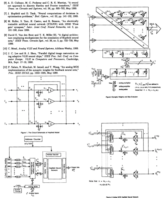
Tp9g9(X9u9), where g q ( . ) is a monotonically increasing sig- moidal bounded function converting potential to firing rate. The gen- eral structure of the networks is shown in Figure 1. The equations of motion are du dt nC p
= -Ife
+ c T p q u q +Ip q=1 UP = SP(XPUP) (11)where Xp's are the amplifier gains and gp(Xpup) is typically identified
as f ( 1
+
tanh(Xpup))Electrically, Tp9uq might be understood to represent the electrical current input to neuron p due to the present potential of neuron q. The quantity Tp9 represents the finite conductance between the output uq and the body of neuron p. It would also be considered to represent the synapse efficacy. The term -up/R is the current flow due to finite transmembrane resistance
R,
and it causes a decrease in up. Ip is any other (fixed) input bias current to neuron p. Thus, according to ( l l ) , the change in up is due to the changing action of all the Tp9uq terms, balanced by the decrease due to -up/R, with a bias set by Ip.Hopfield and Tank [3], [4] have shown that in the case of symmetric connections (Tp9 = Tqp), the equations of motion for this network of analog processors always lead to a convergence to stable states, in which the output voltages of all amplifiers remain constant. In addition, when the diagonal elements (Tpp) are 0 and the amplifier gains Xp's are high, the stable states of a network comprised of n neurons are the minima of the computational energy or Liapunov function
The state space over which the analog circuit operates is the n- dimensional hypercube defined by up = 0 or 1. However, it has been shown that in the high-gain limit networks with vanishing diagonal connections (Tpp
=.
0) have minima only at corners of this space [4]. Under these conditions the stable states of the network correspond to those locations in the discrete space consisting of the 2" corners of this hypercube which minimize E.To solve the minimization problem in (10) by the Hopfield-type neural network, the binary variables s$) should be assigned to their corresponding potential variables up with n (= mij
+
nij+
1) neurons. Truly, the computational energy function Eij of the proposed network for yij may be identified as IlAijll" in (10). However, with this simply energy function there is no guaranttee that the values of will be nearChang, Hwang and Gong: A High-speed Neural Analog Circuit for Computing the Bit-Level
enough to 0 or 1 to be identified as digital logic. Since (10) contains diagonal elements of the T-matrix are nonzero, the minimal points to the llAij112 (10) will not necessarily lie on the corners of the hypercube, and thus represent the 2's complement digital representation. One can eliminate this problem by adding one additional term to the function
IlAi,l12. Its form can be chosen as
The structure of this term was chosen to favor digital representations. Note that this term has minimal value when, for each p, either
st'
= 1 or s$)=
0. Although any set of (negative) coefficients will provide this bias towards a digital representation, the coefficients in (13) were chosenso as to cancel out the diagonal elements in (10). The elimination to
diagonal connection strengths will generally lead to stable points only at corners of the hypercube. Thus the new total energy function EiJ for yij which contains the sum of the two terms in (10) and (13) has minimal value when the s$) are a digital representation close to the resultant
yij in (3). After expanding and rearranging the energy function E i j ,
we have
p=-n,j q=-n.j p=-",j
where
4
Programmable Hybrid Digital- Analog
Neural Implementation
Observing equations (14.b) & (14.c), i t is indicated that the synapse weights and bias are not fixed and depend on input analog signals
zit's
and the index ( i j ) of their corresponding result yij. Both synapse weights and bias should be programmable in order to capture the in- formation from the data set. Several researchers address the issues of programmable neurons. One VLSI chip from Intel [E] was imple- mented fully analog circuity operating in a deterministic manner, while another chip (91 was implemented with fully digital circuits operating in a stochastic manner. In this paper, an novel hybrid neural circuit including compact and electrically programming synapses and bias is described. The circuit techniques are based on extremely simple and programmable analog parameterized
MOS
modules with such attrac- tive features as reconfigurability, input/output compatibility, and un- restricted fan-in/fan-out capability.Before introducing the design of reconfigurable hybrid neural chip, several arrangements should be considered in the expressions of both synapse weigh
q i
and bias 12 as follows:0 for p = q
-2p+q-~m,F.. f o r ~ # q , p # m i j , q # m i j (15.a)
2p+q-2m*~
F..
2p+q-2m.j% for p#
q , p
#
mij,
q=
mijfor p
#
q , p = mij, q#
mijand for p = mij
I
I>-1 L-1 where 339 r=O i = o r.-1 r.-1 (15.c) (15.d) r = O t=O andU. *si,
.
- - 2m*,+1uirutj,o
5
i, j , s , t5
L-
1 (15.e) Basically, the concept of the above arrangements is conducted to categorize the expressions of both and I? into a class of terms as- sociated with the index (i, j ) which corresponds to the resultcj
and another class of terms associated with the index (p,q) which corre- sponds to the size of neural network (or number of bits involved in C i j ) . In addition, (p, 9)-related terms, 2P+g, 2P+', and 22P are normalized by scaling factors 2-'"'8j, 2-"'*., and 2-2m*3-', and thus the ranges of normalized terms 2p+q-2m*j, 2P-"'**, and 22(p-mt~)-1 would lead to be,
1,
respec- within the intervals [2-2(n-1), 1],[2-("-'), 11, and [2-2"-3 2-'tively, where n (= mij
+
nij+
1) is the number of neurons. Therefore, those normalized terms are totally independent of index ( i , j ) . Since2p+q-m1j = 29+p-msJ, this allows the synapse weight
qi
to hold the property of symmetry, that is,rd',
=vi.
This also turns out that only the evaluations located on the upper (or lower) triangle area(Vi
withq
>
p) of the T-matrix are necessary for the Hopfield neural network (note that = 0 when p=
q ) . Based on the above discussion, a p r e posed programmable system architecture and the function structure of each module are illustrated in Fig. 2, Fig. 3, and Fig. 4 respectively.The parameters T i j , and uirtj could be precomputed and are stored in the
((L'
+
1) x L z ) register file which is controlled by an address counter with clock At1. Note that At1 is defined as the sum of Atrejrc.h (= time for refreshing both the synaptic weights and bias) and Atneural (the computation time for the neural network). While computing a particular &'those parameters should be pumped out from the reg- ister file. ATi,
will go to the upper triangle analog multiplier array illustrated in Fig. 3 and thus compute the desired synaptic weightsqi
which are used to dynamically refresh the on-chip programming Hopfield network. Since the Lz input analog signals zSi's are required in computing the A vector multiplication (with ui,tj,O5
s , t5
L
- 1)involved in each Iij, 0
5
i, j5
L
-
1, z.t's should stay in the ana-log buffer until the
L2
fjij's have been completed. This analog buffer is controlled by a system counter yit h clock At2 (= Lz.
A t l ) . Aftercompleting the evaluations of both T& and Ii,
,
the synaptic weights and bias 2:' could be determined according to the values 2P+q-2msJ and2p-m1J respectively. The upper triangle array with zero diagonal used
to compute contains n(n
-
1)/2 analog multipliers, each of whichhas a prescribed operand that is independent of the index (i, j ) . The
implementation of analog multiplier is suggested to employ the
MOS
modified Gilbert transconductance multiplier (or four-quadrant multi- plier) [lo] illustrated in Fig. 5, which has a wide range of both stabitity and linearity. Since each prescribed operand 2p+q-Zm.j is power of two, another solution to implement the evaluations of T-matrix can use the shift registers instead of the analog multipliers. Similarly, two linear analog multiplier arrays are used to determine I l 2 ' s and I2;. '3' s based on the computed values
cj
and6,
from the previous modules. After analog additions, the resultant IF = 11;+
I2;, -nij5
p5
mij would340
IEEE Transactions o n Consumer Electronics, Vol. 37,No.
3, AUGUST 1991be then pumped into the neural network. The synaptic weights and bias from a digital register file are converted to analog form through an evaluator module and then written on the storage capacitors or analog DRAM-type storage (111 inside the Hopfield neural network selected by the address decoder. The circuit schematic of a Hopfield neural network is shown in Fig. 4. The neurons are realized by simple CMOS double inverters which are interconnected through the n (= mi,
+
nij+
1) vector multipliers. The transfer function of the double inverter is iden- tified as the montonically increasing sigmoidal function, g,(X,u,). Each multiplier illustrated in Fig. 6 implements the scalar vector productor of the vector of neuron outputs (sf])’s) and the vector of the synaptic weights. For a network of n neurons, there are n such scalar produc- tors. Each scalar product is achieved using only one operational ampli- fier and 4(n+
1) MOS transistors for 2n-tuple vector inputs resulting in an economic and attractive analog MOS VLSI implementation.Us-
ing depletion transistors, gates of MOS transistors can be connected to ground resulting in a special case of the vector multiplier which allows the multiplication of voltages that are referred to ground. Positive or negative grounded voltage levels can be assigned to synaptic weights,
e.
The outputs of n neurons si:) (-ni,5
q5
mi,) are fedback as inputs to the p t h multiplier (-nij5
p5
mi,). The output of the p t h multiplier in turn is fed into the input of the p t h double inverter (neu- ron p). The overall output of the p t h vector multiplier, u t ) is givenm.1
by
ut; = c x
q
q
x 6;;) (16) q=-n.,where c = the constant depends on the characteristics of MOS imple- mentation.
It is interesting t o note that the constant c could be compensated by absorbing the values into
?J
For example, one may precompute the new5,
as c-l xf&,
where zj is the old one. The input-output com- patibility of the overall MOS implementation is of particular interest since the relatively high output impedance node of the double inverter is connected to the almost inifinite input impedance node of the MOS- FET gates with almost no restrictions on the fan-in/fan-out capability. More details about the MOS vector multiplier are shown in [12].5
Illustrated Examples
To examine the performance of the neural-based analog circuit for computing the 2-D DCT transform coding, an often used 8 x 8 DCT will be considered in our simulation since it represents a good compromise between coding efficiency and hardware complexity. Because of its effec- tiveness, the CCITT H.261 recommended standard for p x 64 kb/s(p
=
1, 2 , .
.
.30) visual telephony developed by CCITT, and the still-image compression standard developed by IS0 JPEG all include the use of 8 x 8 DCT in their algorithms.In order to obtain the size (= n) of neural network required for computing its corresponding DCT coefficient, it is necessary t o calcu- late their respective dynamic range and to take into account the sign bit. To achieve this purpose, the range of each DCT coefficient can be determined by generating random integer pixel data values in the range 0 to 255 through the 2-D discrete cosine transform. For example, the range of yo0 is from -1024 to 1023. Therefore, moo is identified as 11, that is, 10 bits are for the magnitude of yo0 and 1 bit is for sign. As a re- sult, the corresponding m,> for each DCT coefficient y,, is illustrated in Table 1. Another important parameter required in determining the size is n,, which depends on the required accuracy and the tolerable mi* match in the final representation of the reconstructed video samples. The analysis of the accuracy and mismatch involved in the finite length arithmetic DCT computation has been discussed in [l], [2]. Based on their results and the consideration of feasibe hardware implementation, the number of bits (or size of neural network) involved in each DCT cosfficient is set to be 16. Then, nV would be equal to (15
-
m,,), for example, no0 = 5. The above skggestion seem quite reasonable for improving the accuracy of a particular y,, which has a small dynamicrange.
We have simulated the DCT-based neural analog circuit of equa- tion ( l l ) , using the simultaneous differential equation solver (DVERK in the IMSL). This routine solves a set of nonlinear differential equa- tions using the fifth-order Runge-Kutta method. It is known that the converge time for neural network is within RC time constant. We used three different RC time constants, RC = lo-’’ (R = l k R , C =
O.OlpF), RC = (R =
lkR, C = I pF ) and all amplifier gains X,’s are assigned t o be 100 in our experiments, and ran simulations on a SUN workstation. The test input pixel data Z , ~ ’ S are illustrated in Table 2.(a). Figures 7.a, 7.b &
7.c show an example of the time evolution of the reduction of energy performed by a network with n (= 16) neurons that represent y25 based on the 2’s complement binary number representation for three different RC time constants. The (2,5)-entry in Table 2.(c) shows the resulted DCT coefficient ~ 2 5 obtained at the steady state points on the curves of Figures 7.a, 7.b & 7.c. It is shown that the result is almost inde- pendent of the RC time constants. However, each converge time will be in proportion to its corresponding RC time constant. For example, the converge times for RC = 10-lo, RC = and RC = are in proportion to the orders of time scale, 10-l0sec (= O.lns), 10-gsec (= Ins), and lO-%ec (= lOns), respectively. But these three curves have almost the same time evolution. Starting from very high energy state, the neural network reduced its energy spontaneously by changing its state 80 that the 2’s complement binary variables s$)*s minimize the error energy function.
Considering the programmable neural MOS circuit implementation of an 8 x 8 DCT based on the above results, both address clock At1 and system clock At2 for RC = are estimated as 2ns and 128ns respectively with the estimated Atrefte,h = Ins. Therefore the com- putation time for computing all DCT coefficients would be estimated
as 150- which includes the overhead of I/O. The real implementation of the analog MOS neural circuit will be realized in our microelectronic laboratory.
(R = l k R , C = O.lpF), and RC =
6
Conclusion
The computation of a 2-D DCT-based transform coding has been shown t o solve a quadratic nonlinear programming problem subject to the corresponding 2’s complement binary variables of 2-D DCT coeffi- cients. A novel Hopfield-type neural analog circuit designed to perform the DCT-based quadratic nonlinear programming could obtain the de- sired coefficients of an 8 x 8 DCT in 2’s complement code within Ins with RC = lo-’. In addition, a programmable analog MOS implemen- tation provieds a flexible architecture to realize the DCT-based neural net.
References
[l] M. T . Sun, L. Wu, and M. L. Liou, “A concurrent architecture for VLSI implementation of discrete cosine transform,” IEEE Iltnns.
on Circuits and Systems, vol. CAS-34, pp. 992-994, Aug. 1987.
[2] M. L. Liou and J . A. Bellisio, “VLSI implementation of discrete cosine transform for visual communication,” in Pwc. Int. Conf. on Commun. Tech., Bejing, China, Nov. 1987.
[3] J. J. Hopfield, “Neurons with graded response have collective com- putational properties like those of two-state neurons,” Pmc. Natl. Acad. Sei., U.S.A., vol. 81, pp. 3088-3092, 1984.
[4] D. W. Tank and J. J. Hopfield, “Simple ‘Neural’ optimization net- works: An A/D converter, signal decision circuit, and a linear programming circuit,” IEEE Itnns. on Circuits and Systems, vd.
CAS-33, no. 5, pp. 533-541, May 1986.
[5] G. Bilbro, M. White, and W. Snyder, “Image segmentation with neurocomputers,” in Neurul Computers, Rolf Eckmiller and Christopher v. d. Malsburg, Eds., pp. 71-79, Springer-Verlag, 1987.
341
Chang, Hwang and Gong: A High-speed Neural Analog Circuit f o r Computing the Bit-Level
[6] A.
D.
Culhane, M. C. Peckerar and C. R. K. Marrian, “A neural net approach to discrete Hartley and Fourier transform,” IEEE?fnns. on Circuits and Systems, vol. 36, pp. 695-702, May 1989. [7] J . Hopfield and
D.
Tank, “Neural computations of decisions in optimization problems,” Biol. Cybem., vol. 52, pp. 141-152, 1985.[E]
M. Holler,S.
Tam,H.
Castro, and R. Benson, “An electrically trainable artificial neural network (ETANN) with 10240 ‘Float gate’ synapses,” Inter. Joint Conf. Neural Networks, vol. 2, pp. 191-196, June 1989.[9] David
E.
Van den Bout and T . K. Miller 111, “A digital architec- ture employing stochasticism for the simulation of Hopfield neural nets,” IEEE %ns. Cirruits Syst., vol. 36, no. 5, pp. 732-738, May 1989.[lo] C. Mead, Analog VLSI and Neural Systems, Addison-Wesley, 1989. [ll] J. C. Lee and B. J . Sheu, “Parallel digital image restoration us-
ing adaptive VLSI neural chips,” IEEE Pwc. Zntl. Conf. on Com- puter Design: VLSI in Computers and Processors, Cambridge,
MA, Sept. 17-19, 1990.
.2] F. Salam, N. Khachab, M. Ismail, and Y. Wang, “An analog MOS implementation of the synaptic weights for feedback neural nets,”
Proc. IEEE ISCAS, pp. 1223-1225, May 1989.
0
Figure 1. The Circuit Schematic 01 Hopfield Model
X.1
Faure.2 Architecture of Imam Transform codinp Neural Chip
Fqure.3 Synwic WeiQhu and Bias EvaIualor
I . .
.
. . . . . . . . . . . . . . . ..
“ _Note that :n
-
mi + ni,IEEE Transactions
on
Consumer Electronics, Vol. 37, No. 3, AUGUST 1991Fipure.5 Modified-Gilberl Prwrammable Anab Multiplier Fipure.6 Veclor MuHiplier(Anabp MOS)
RC=l.OE-lO;Lamda= 100 time in sec F i g u ~ . 7 ( a ) X10'0 X l W RC=l.OE-9&mda=100 " " " " time in sec X I 0 9 Figure.'l(b) XI@ RC= l.OE-8;Lamda= 100 ,