Proceedings of the American Control Conference Arlington, VA June 25-27, 2001
Variable structure contml of unknown parameters dc servo systems
using
CMAC-based learning approach
Wei-Song Lin and Chin-Pao Hung Institute of Electrical Engineering
National Taiwan University Taipei, Taiwan, R0.C.
Abstract
A CMAC-based controller with a compensating neural network and an update rule is proposed to design the variable structure control (VSC) of unknown parameters dc servo systems. By introducing a stabilizer controller and a CMAC neural network to construct the VSC control law, the new control scheme performs the equivalent control by a real-time learning algorithm. The stabilizer controller is designed by using Lyapunov stability theory and the updating rule of the CMAC weights is obtained by using the gradient descent method. Simulation results of a simplified robot link model demonstrate the effectiveness and robustness of the proposed controller.
I . Introduction
A variable structure controller (VSC) design usually needs the mathematical model of system. When the exact plant model is not available, a nominal model with bounded uncertainty is usually assumed so that a robust control law can be obtained [l-31. In these conventional schemes, the control laws design need the system model. If the system models are unknown, these control laws cannot be implemented. To solve the unknown parameters problem, many researchers proposed fuzzy sliding mode control (FSMC) using
IF-THEN
linguistic rule to achieve a robust controller [4-61. However, thesefuzzy
schemes usually need the expert experience, and the design process is tedious. In the past decade, several investigators have presented learning control schemes for improving the control perfonnance of traditional control methods or to solve the unknown model problems [7-81. Based on the repetitive operations, the control object can be achieved perfectly. Miller in [9] proposed a real-time learning scheme for industrial manipulator control using the CMAC network. In [9], the CMAC network is used to learn the inverse dynamic of industrial robot. The combination of CMAC and a futed gain controller make the real-time control possible, whereas only few publications use neural network to solve the problems of VSC to system without the plant model. Until 1999, Bottura [lo] introduced CMAC network into the VSC to reach the hitting condition forsystem without the knowledge of system parameters. However, Bottura only proposed an elementary idea; systematic design steps and the theoretical demonstration are lacking.
CMAC (Cerebellar Model Articulation controller) is developed by Albus
in
the 1970’s[11]. It is like the models of human memory, using local data to perform reflexive processing. Therefore it’s learning speed is very fast and this makes it attractive to on line application in control system [12]. This article considers the VSC controller design of unknown parameters DC servo systems. By introducing a stabilizer controller to guarantee the stable learning, a CMAC neural network with learning algorithm is constructed to learn the equivalent control of VSC. This is unlike the conventional VSC, which is a parametric scheme where any change in the performance requirements necessitates the design work to be re-performed. The CMAC approximates and performs the equivalent control depending on the uncertainties and the constraints of the desired sliding surface. Therefore, redesign is not necessary for any parameter change in the performance requirements or the controlled plant. With application of this scheme to the motion control of robot manipulator, computer simulations demonstrate the success of the proposed method.2. Problemformulation
following error dynamic equation [ 151:
i i ( t ) = ~ i + l ( t ) i = l , - . - , n - l
x n ( t ) = - c u i (t)xi
-
b(t)u(t)-
fwhere x,(t) is the error state output, U is the control
command, f is the disturbance, ui(t),b(t) are the unknown bounded plant parameters and b(t)>O
.
Therefore, the control objective of this paper can be describe as follows [14]:Determine a feedback control u(x1wJ (based on Consider a dc servo system described by the
n
(1) i=l
CMAC neural network)
and
a learning law for adjusting the vector such that the following conditions are met:The close loop system must be globally stable in the sense that all variables,E(t),dt) and u(xlwJ, must be uniformly bounded; i.e., b(t)ls
M,
< Q),
b ( t ) [ < M w < w and ~ u ( x ~ ~ ) I ~ M ~ c w
,
M,
,
M,
,
M u are design parameters specified by thedesigner.
The tracking error xl, should be as small as possible
under the constrains in 1) and
-
X = ( X I , X 2 , X ~ , - . , X n ) = (Xl,X~,...,X~ + l ) l T satisfy thesliding surface model given by
(2) n
c = C c i x i = 0, i = ~ ; . . , n , cn = 1
which the
ti's
are all real andi=l
h(s) =
F1+
C ~ . . , ~ S " - ~+...+
c1 is Hurwitz polynomial. 3.TheVSC design using CMAC-based learning approach 3.1 The structure of proposed controllerGenerally, the VSC control law can be decomposed into [ 151
here ueq, called the equivalent control, is defined as the solution of u = O under free uncertainty and Au is constructed to satisfy the hitting condition, i.e. m a < 0 . In the conventional scheme, the equivalent control is derived from the system nominal model. If the system parameters are unknown, the control law cannot be implemented.
As described above, if the exact system model is known
u=ueq+A14 (3)
i=l
Substituting (1) into (4), we have
n-l
z c i x i + ,
-
x a i ( t ) x i-
b(t)u(t)- f = 0i=l i=l
Then the optimal equivalent'control U * is
Applied to (1) results in
xi ( t ) = Xi+l(t) i = 1;. .,n
-
1Therefore, under ideal sliding motion, the system described by (1) can be reduced to
i i ( t ) = xi+l (t ) i = l,...,n
-
1The eigenvalues of the system can be set arbitrarily by choosing the value of
ci,
i = l , . . . , n - l.
If the sliding surface satisfies the Hurwitz stability, which implies thatlim x1 (1 ) = 0 , the main objective is achieved. Since the system parameters are not exactly known, the optimal equivalent control cannot be implemented.
Our
purpose is to design a VSC controller using CMAC-based learning approach to approximate the optimal equivalent controlt+a
*
U .
Let the control function ~ ( 5 1 ~ ) be decomposed into
U(X
1
9
= U N(x
IF) + U, (5)where U ~ ( X
1
9
is a CMAC neural network output,and
U,
(z),
a stabilizer control, will be determined later.Substituting (9) into (l), we have Xi(t) = x i + , ( t ) i = 1 >... ,n
-
1(9)
i=l
Now subtracting and adding b(t)u* to (IO) and after some straightforward manipulation we obtain the error equation goveming the closed-loop system:
4t)=%+l(O i=V.;n-l
1 i = l
Define a standard Lyapunov function is
(13)
2
Then
V = u & (14)
Taking the time derivative of c y and using the error equation (12), we have
V = - u 2 1
n n-1
a
=&Xi =xn
+
Our task now is to design U, such that 5 0
.
In order to do so, we need the following assumption:Assumption 1: We can determine the parameter bounds
such that
i = I , . . . , n
,
O < b L I b ( t ) and[ f l ~ f "
Iai(t)l<uU ,
Therefore, we construct the U, as follows:
where sat(z) is a saturation function defined as follows. E
d
sat(-) = , E is a small positive constant
(20) Substituting (19), (20) and (6) into (1 8), and considering the
2 1 case, we have
1 0 (21)
Therefore, using the stabilizer control U,, we always have
.f.b
1
< 1.
Choose a suitable E value the sliding surface functionla1 will be less than E.
Since sliding surface function cr satisfies the Hurwitz stability condition, theboundedness of 6 implies the boundedness of error
statex. The bounded range can be found in [18]. If we rephce the sat
-
term of U, as sgn(a), then we canguarantee the error& converging to zero. But U, is a
discontinuous h c t i o n and is proportional to the parameter upper bound, which is usually very large. Using a saturation function can smooth the control signal. Since us is used to force the system trajectory to move along the sliding surface, a smalk U value implies the u N part is well behaved. Large stabilizer control signals are not necessary.
3.2 Learning process
The CMAC network is used to learn the optimal equivalent control signal U*. If the CMAC learned the U*
,
then the output trajectory will stay on the sliding surface and is equal to zero, insofar as we can let the sliding surface be the teacher of the CMAC. At each control cycle, the desired sliding surface determines the desired state of the system xd for the next control cycle. The desired next state is sent to the CMAC network to produce u N.
u N is assumed to be the estimation of the real equivalent control signal required to achieve the ideal sliding mode control. It adds the output of the U, (xJ to form the controller signal U for the robot actuator drivers.At the end of each control cycle a training step is executed. The observed sliding surface of the system during
the
previous control cycle is used to modify the weighting values. Generally the following simple steepest-descent update rule is used in most CMAC-based learning systems(22)
wi = wi
+fl-
In this equation, ud =
o
is the desired sliding surface, Qthe actual output, A* the number of association memory cells, and
fl
is the learning factor.3.3 Control algorithm
As described above, the structure of the proposed scheme is shown in Fig. 1 and the control algorithm is summarized as follows:
Step 1. Specify the sliding surface function vd that Step 2. Spec@ the design parameters M , , M , and
Step 3. Transform the sliding surface to the desired error
(9
11p7-181.
( a d
-
6) A*satisfies the Hurwitz stable condition.
M , based on practical constrains.
Step 4. Send the desired next error states x d ( t ) to the Step 5. Perform a series of mappings to transform the
input values to the CMAC output Step 6. Calculate the stabilizer control signal u , ( t )
Step 7. The U&) is assumed to be an optimal
equivalent control signal and is added to the output of the u,(t) to form the control signal
u ( t ) = u,(O +
Step 8. Send ~ ( t ) to plant to produce the actual output
Step 9. Calculate the values of the actual sliding surface Step 10. Update the fired weights using equation (22)
CMAC network
( t )
states x,(t) function a(t)
Step 12. If I l x o ( t ) l l ~
,
stop. ( E l is a small positive value.) Otherwise, go to step 3.4. Numerical example 4.1 Uncertain DC servo system
Considering a robot system driven by DC motors of Fig. 2, the open loop step response curve was shown in Fig.
3. From the response curves, the link 1 model can be identified as following:
(23)
XI (0 = xz
0 )
i z ( t ) = 0x1 - (33 f 5 ) X z
-
(300 f SO)Uwhere x1 = 6, -6
.
6 d is the desired end-effector output and 0 is the actual output. The simulation model for demonstrating the effect of the proposed scheme is described as followinp;.-
4.2 Selection of sliding surface
surface [15] and the sliding function described as follows:
As shown in Fig.4, we chose two segments sliding
(25)
a2 = C l X l + x z (26)
where amax represents the maximum acceleration signal of error output and c, is the slope,.of deceleration segment. The segment a, is used to steer the transient state to move along a predefined surface. The derivation of control law is same as segment az
.
4.3 Simulation results and discussions associated parameters are listed in Tablel.
Cl=-XI --xi 1 +xg
2%ax
The simulation results are shown in Fig 5-6. The
To examine the robustness property of the control scheme, we use a different sliding surface and keep the same controller structure to demonstrate the possibility of the proposed method. It is clear that the proposed approach can give an almost accurate servo tracking response to unknown
parameters system (Fig. 5(b)(c)). Figs. 5(d) and 6(d) show the waveforms of control functions, and we see that the CMAC outputs are dominant gradually. The
C M A C
network can learn the approximated equivalent control on line. It is noted that the initial values of all the memory locations have small non-zero values. Since the initial state is located on the sliding surface, i.e. Q = 0, a zero initial value will lead to the system being unable to self-start.
5. Conclusion
In this paper, a new variable structure control scheme is proposed to solve the unknown parameter problems of VSC. A Ch4AC network is used to learn the equivalent control of VSC for the unknown system model. A stabilizer controller based on Lyapunov synthesis approach is designed to guarantee the stability of the proposed scheme in the sense that all signals involved are uniformly bounded. This non-parametric ’scheme doesn’t need the system model to design the controller parameters. Using the generalization property of CMAC, the new control scheme can learn the approximated equivalent control signal on line and yield a robust sliding mode control. Applying this scheme to the simplified robot manipulator system, it can produce a variable structure control signal for different performance requirement or parameter bounds. The simulation results demonstrate the success of the proposed scheme to robot control with unknown parameters.
6. Reference
1. K. K. D. Young, ” Controller design for a manipulator
using theory of variable structure systems”, IEEE
Trans. Syst., Man, Cybem.
,
vol. SMC-8,
no. 2, 2. J. J. Slotine, S. S . Sastry, “Tracking control of nonlinear systems using sliding surface, with application to robot manipulators”,J.
Control, vo1.38, no. 2, pp. 465-492, 1983.K. S. Yeung, Y. P. Chen, ”A new controller design for manipulator using the theory of variable structure systems”, IEEE Trans. Automation Control, vol. 33, no. 2, pp. 200-206, 1988.
4. C. C. Kung, C. C. Liao, ”Fuzzy-sliding mode pp. 101- 109, 1978.
5. 6. 7. 8. 9. 10. 11.
controller design for tracking control of non-linear system”, Proc. of American Control Con$, pp.
S.
Bentalba, A.E.
Haijaji, A. Rachid, ”Fuzzy sliding mode controller of mobile robot”, ZEEE Conf: onDecision andContro1, pp.4264-4265,1998
B.
Yoo, W. Ham, “Adaptive fuzzy sliding modecontrol
of
nonlinear system”, IEEE Trans. oncFuzzySytem, vol. 640.2, pp. 315-321, 1998.
S. Kawamura, F. Miyazaki, S . Arimoto, “Realization
of robot motion based
on
a learning method”,IEEE
Trans. Syst., Man, Cybern., vo1.18, no. 1, pp. 126-134,
1988.
S . R. Oh, Z. Bien, €1 Hong Suh, ”A model algorithmic
learning method for continuous-path €ontrol of a robot manipulator,” Robotica, vol. 8, pp. 31-36, 1990.
W.
T. Miller, R. P. Hewes, F. H. Glanz, and L. G. Kraft. “Real-time dynamical control of an industrial manipulator using a neural-network-based learning controller“, IEEE Trans. Robotics Automat., vol. 6, no.1, pp. 1-9, 1990.C.
P.
Bottura, M. C. M. Teixeira, M. J. Borden, ‘‘ Stabilization of an inverted pendulum with CMAC in a variable structure controller“, Proc. of AmericanControl Con., San Diego, California, pp. 1042-1046,
1999.
J.
S.
Albus, “A new approach to manipulator control: 180-184, 1994.t
Fig. 1 Block diagram of proposed control scheme
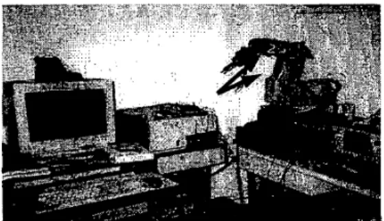
Fig. 2. Photo of robot manipulator system
12. 13. 14. 15. 16. 17. 18.
the cerebeller model articulation controller (CMAC)’
,
Trans. ASME
J.
Dynam., Syst., Meas., and Con@., vol.D.
A. Handehan,S.
H. Lane, and J. J. Gelfand, “Integrating neural networks and knowledge-based systems fer intelligent robotic control“ 9 IEEE Control System Magazine, pp. 77-86, 199Q.K. S. Fu, R.C. Gonzalez, C.S.G. Lee,” ROBOTICS: control, sensing, vision, and intelligence”, McGRAW-Hill, 1987.
L. X.
Wang, “Stable adaptive f k z y control ofnonlinear system”, IEEE Trans. on F u z q Sytem. vol. 1,no. 2, pp. 146-155, 1993.
T.
L.
Chem, J. S. Wong,”DSP
based integral variable structure control for DC motor servo drivers”, IEEProc. Control Theory Appl. vol. 142, no. 5, pp.
A. Davari, and Z. Zhang, “Application of the three-segments variable structure systems”, Proc. Am.
Control Conf, 1, pp. 62-63, 1991.
M. Sznaier,”Robust control of dynamic systems using neuromorphic controller: A CMAC approach”, ZEEE
Con. on Decision and Control, pp.2710-2715, 1992.
Y. F. Wong, A. Sideris, “Learning convergence in the cerebellar model articulation controller”, ZEEE Trans. on Neural Network, vol. 3,110. 1, pp. 115-121,1992. 97, pp.220-227,1975
444-450, 1995.
robal system responae lor dillerant level
100
c
0.1 0.2 0.1 0.4 0.5 0.6 0.1 0.B
-300; . ’ . . . ’ .
’
Ifme(aa0)
Fig. 3 Open loop step responses for different input leveh
I
0 200 400 8 0 0 8 0 0 1000 1 2 0 0 -0.05
'
Fig. 5(a) Weight value of memory cells for CMAC network
. . . . ... x d I x i
-
. ' d 2 ... x 2-
. 4 , . 4 1 U' X 2 (rad IFig. 5(e) Phase plane plot of desired and actual output states
0.25 0.2 0.15 0.1 0.05 0 I 0 2 0 0 400 8 0 0 8 0 0 1 0 0 120 -0.05
'
Fig. 6(a) Weight value of memory cells for CMAC network
...
x d I
-
0:6 0:8 1 ' 2 1'.4 1:8 l i e c ,
Fig. 6(b) Desired and actual output state XI
volt
Fig. 6(c) Desired and actual output state x2
r . . . I
Y.
.".
Y. ..,..I.
. I D. a . 0 . 3 * I , a 3 .Fig. 6(d) CMAC output and the U, output
X 2 (rad I