國
立
交
通
大
學
機械工程學系
博
士
論
文
驅動訊號波形、噴孔幾何參數與噴孔流道親疏水
性對噴墨頭液滴噴射行為影響之研究
Investigation of the effect of a transducer pulse, nozzle
geometry and liquid hydrophobicity on the drop formation of an
ink jet printhead
研 究 生:賴志銘
指導教授:林振德 教授
驅動訊號波形、噴孔幾何參數與噴孔流道親疏水性對噴墨頭液滴噴射
行為影響之研究
Investigation of the effect of a transducer pulse, nozzle geometry and
liquid hydrophobicity on the drop formation of an ink jet printhead
研究生:賴志銘 Student:Jr-Ming Lai指導教授:林振德 Advisor:Dr. Jenn-Der Lin
國 立 交 通 大 學 機 械 工 程 學 系
博 士 論 文
A Thesis
Submitted to Department of Mechanical Engineering College of Engineering
National Chiao Tung University in partial Fulfillment of the Requirements
for the Degree of Doctor of Philosophy
in
Mechanical Engineering July 2010
Hsinchu, Taiwan, Republic of China
i
驅動訊號波形、噴孔幾何參數與噴孔流道親疏水性對噴墨頭液滴噴射
行為影響之研究
學生:
賴志銘 指導教授: 林振德 博士
國立交通大學機械工程學系博士班
(熱流組)
中文摘要
本研究利用數值模擬的方法,探討驅動訊號波形對ㄧ壓電式噴墨
頭液滴噴射行為之影響。為了對驅動訊號波形與液滴形成之關係有一
完整的了解,研究中將一雙極方波訊號區分成供液段、補液段、噴出
段、間歇段、回拉段與靜止段,並找出每一波形區段的獨立參數,分
析不同區段不同獨立參數組合,對噴出之主液滴體積、主液滴飛行速
度、液滴斷裂時間與衛星液滴形成之影響。數值模擬部分,採用商業
化計算流體力學軟體
CFD-ACE+來進行;透過邊界條件給予相對於電
壓訊號之壓電隔板形變位移量以模擬不同訊號波形之壓電致動行
為;利用流體體積-片段線性界面重建法來做液氣界面的時變追蹤,
並以連續表面力法來考慮流體表面張力的效應。研究結果顯示,主液
滴體積主要與訊號噴出段所造成最大腔體形變量有關;主液滴飛行速
度主要與訊號噴出段之斜率有關。此外,縮短訊號間歇段能有效地抑
制衛星液滴的形成。為了探討噴孔流道親疏水性與噴孔流道曲率對液
滴噴射行為的影響,我們簡化液滴生成與噴射機構,採用一噴孔片透
ii
過壓電材料的形變振動,將液體噴射而出的設計。研究中首先利用
CFD-ACE+建立一數值模型,再設計一液滴噴射實驗,利用實驗觀測
結果來驗證數值模型。研究結果顯示,當噴孔直徑越小,主液滴體積
越小,主液滴飛行速度越快。當噴孔片振動振幅越大或振動頻率越
快,會使主液滴體積變小,主液滴飛行速度變快。此外,在所考慮不
同流道曲率中,線性流道曲率會產生較小主液滴體積和較快的主液滴
飛行速度。當噴孔流道表面由親水變化到疏水時,主液滴體積會變
小,主液滴飛行速度會變快。
iii
Investigation of the effect of a transducer pulse, nozzle geometry and
liquid hydrophobicity on the drop formation of an ink jet printhead
Student: Jr-Ming Lai
Advisor: Dr. Jenn-Der
LinDepartment of Mechanical Engineering
National Chiao Tung University
ABSTRACT
Numerical calculations were performed to investigate the effect of the component of a single transducer pulse on the ejection of a drop for a drop-on- demand ink-jet printhead with a piezoelectric actuator. The flow field is governed by continuity and Navier-Stokes equations. A volume-of-fluid method with a piecewise-linear interface construction is used to track the complicated topological variation of the liquid-gas interface. The computer code was validated with experimental results present in the literature. The volume of the primary drop is closely related to the maximum displacement Df of chamber wall induced by
piezoelectric actuator in the forward stroke; the velocity of the primary drop depends on the ratio of Df to the time period of the forward stroke, ∆τ f. Moreover, the
iv
considered. A decreased interval between forward and backward strokes might serve to suppress the formation of satellite drops owing to reducing the liquid thread length
b
l at pinching off to a value less than the upper limit *
b
l . The breaking up of freely flying liquid thread from nozzle outlet has two modes – multiple breaking up and end pinching, and depends on the thread length at pinching off. In an investigation of the influence of liquid hydrophobicity and nozzle geometry on the drop formation process, a system of a nozzle plate connected to a flat-plate piezoelectric material was designed. The numerical models of the designed system were constructed and validated by comparing simulation results with experimental observations. The numerical results show that a decrease in nozzle exit diameter causes a decrease in drop volume and an increase in drop velocity. When the vibrational amplitude or frequency of the nozzle plate increases, which raises the input energy, drop volume appears to decrease and drop velocity to increase. Besides, the linear-type curvature seems to produce smaller drop volume and larger drop velocity. When the contact angle varies from 7.10 to 1700, drop volume seems to decrease and drop velocity to
v
誌 謝
這篇論文能夠完成,首先我要感謝林振德老師在這段期間的指
導,老師對於物理觀念上適切的引導,幫助我在進行論文研究時能夠
有清晰的思路,此外,老師也教導我們以較為嚴謹的邏輯來處理論文
的每一個環節,這樣的訓練相信對於將來在面對問題與解決問題時,
會有很大的幫助。在此謝謝老師,不管多忙,都一定抽出時間關心我
們的研究與生活,謝謝。
感謝口試委員洪勵吾教授、吳志陽教授、傅武雄教授、陳慶耀教
授與許隆結副教授對於論文上的指正及建議。
感謝吳宗信教授對於數值平行計算的協助,感謝工研院電光所楊
進成博士對於噴墨頭模型建構的協助,感謝同步輻射中心林劉恭博士
對於論文上的協助與討論,感謝學弟昌彥與志豪在論文研究上的幫
忙。
我非常珍惜在交大的每一個日子,感謝學長涂文福、已畢業與未
畢業的學弟們對於我的照顧,你們都是我生命中的貴人。感謝家人的
支持,讓我順利完成學業。感謝董老師與范老師在精神上的鼓勵。
vi
Table of contents
中文摘要
...i
Abstract...iii
誌謝
... v
Table of contents...vi
List of tables...viii
List of figures...ix
Nomenclature...xv
Chapter 1. Introduction...1
1.1 Background...1 1.2 Literature survey...21.3 Motivation and objectives...7
Chapter 2. Theoretical models and computational methods...13
2.1 Interfacial flow models...13
2.2 Modeling of a transducer pulse...18
2.3 Computational methods...20
Chapter 3. Simulation results and discussion...26
3.1 Grid convergence and model validation...26
3.2 Forward stage...29
3.3 Backward stage...34
3.4 Pause stage...37
3.5 Suppression of satellite drops...38
3.6 Supply, refill and equilibrium stages...46
3.7 Effect of the Ohnesorge number...48
vii
on a drop ejection process...81
4.1 Physical model and solution methods...81
4.2 Experimental methods and conditions...84
4.3 Results and discussion...88
4.3.1 Model validation...89
4.3.2 The effect of the orifice diameter...91
4.3.3 The effect of the curvature of the nozzle passage...93
4.3.4 The effect of the dynamic contact angle...95
Chapter 5. Chapter 5. Conclusions and future work...117
5.1 Conclusions...117
5.2 Future work...121
References...122
viii
List of tables
Table 1. Interval for a liquid thread from a nozzle outlet to pinch off, with three
meshes……….…51
Table 2. Velocity of the drop head with three meshes………...………51
Table 3. Primary drop volume with three meshes……….51
Table 4. List of experiments for the forward stage………51
Table 5. List of experiments for the backward stage……….52
Table 6. List of experiments for the pause stage…...………52
Table 7. List of additional experiments...52
Table 8. Liquid thread length at pinch-off compared with prediction...53
Table 9. Estimate of the critical value of the thread length at pinching off...53
Table 10. List of experiments for the supply stage...53
Table 11. Parameters for the grid dependence test...97
Table 12. Parameters for the validation cases...97
Table 13. Parameters and size information pertinent to types of passage curvature...97
Table 14. Parameters and size information to investigate of the effect of contact angle...97
ix
List of figures
Figure 2.1. (a) Schematic of printhead (Picojet) and (b) its computational
domain...23
Figure 2.2. (a) Temporally dependent function of wall displacement and (b) temporal profile of the voltage signal and displacement of the wall beside the piezoelectric transducer...24
Figure 2.3. Flow chart of the principal algorithmic steps...25
Figure 3.1. Numerical grids of a printhead (Picojet)...54
Figure 3.2. Comparison between experiment and numerical simulation...55
Figure 3.3. Key stages observed in our numerical experiment 4: (a) ejection, (b) stretching, (c) necking, (d) pinching off, (e) recoil and (f) breaking up...55
Figure 3.4. Evolution of the liquid thread shape and velocity vector at the liquid side: experiments (a) 2, (b) 1 and (c) 3...56
Figure 3.5. Variation of (a) the volume of the primary drop and (b) the velocity of the primary drop in experiments; the volume is in units of 044 . 5 3 = noz R pL and the velocity in units of Rnoz /tca =2.056 m s-1...57
x
nozzle entrance: (a) experiments 3 and 6, and (b) experiments 4 and 7...58 Figure 3.7. Variation with experiments of pinch-off time of liquid thread from
nozzle exit; the time is in units of tca=8.341 µs...59
Figure 3.8. Variation of the volume of the primary drop and velocity of the primary drop in experiments; the volume is in units of Rnoz3 =5.044
pL and the velocity in units of Rnoz /tca =2.056 m s-1...60 Figure 3.9. Evolution of the shape of the liquid thread during the backward
stroke...61 Figure 3.10. Temporal variation of the rate of volume flow...62 Figure 3.11. Variation with experiments of pinch-off time of liquid thread from
nozzle exit; the time is in units of tca=8.341 µs...63
Figure 3.12. Temporal evolution of the liquid thread shape in experiments (a) 1 and (b) 12...64 Figure 3.13. Temporal evolution of the liquid thread shape in experiments (a) 8
and (b) 15...65 Figure 3.14. Variation of the volume of the primary drop and velocity of the
primary drop in experiments; the volume is in units of Rnoz3 =5.044
xi
Figure 3.15. Variation of duration of the liquid thread pinching off from nozzle exit; the time is in units of tca=8.341 µs...67
Figure 3.16. Temporal evolution of the free surface contour of the liquid thread crossing the period of actuation of the backward stroke...68 Figure 3.17. Satellite formation by multiple breaking up observed in numerical
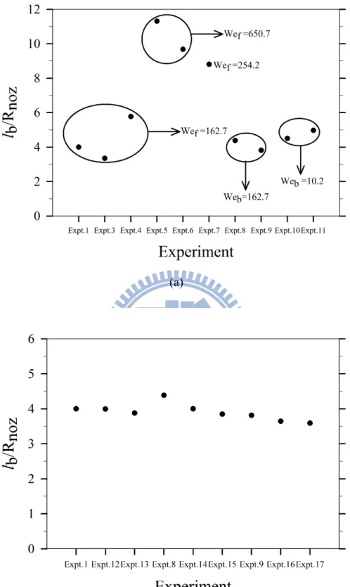
experiment 6...68 Figure 3.18. Variation of length of the liquid thread at pinching off with varied
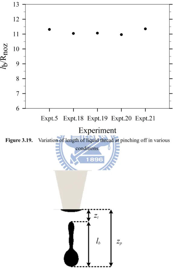
conditions in (a) forward and backward stages, and (b) the pause stage...69 Figure 3.19. Variation of length of liquid thread at pinching off in various
conditions...70 Figure 3.20. Schematic diagram of representative points during the evolution of
an ejected liquid thread...70 Figure 3.21. Variation of c with experiments shown in Tables (a) 4 2
and (b) 7...71 Figure 3.22. Temporal variation of the position of the free surface along the
center line of the nozzle...72 Figure 3.23. Temporal variation of the rate of volume flow rate at the plane of the nozzle entrance...73
xii
Figure 3.24. Variation of the primary drop volume and velocity with firing
frequency...74
Figure 3.25. Variation with the Ohnesorge number Oh of the volume of the primary drop and velocity of the primary drop in experiments; the volume is in units of Rnoz3 =5.044 pL and the velocity in units of 056 . 2 / ca = noz t R m s-1...75
Figure 3.26. Temporal variation of the rate of volume flow...76
Figure 3.27. Temporal variation of the liquid thread shape: (a) Oh=0.15, (b) Oh=0.2 and (c) Oh=0.5...77
Figure 3.28. Variation with the Ohnesorge number Oh of the pinching-off and breaking-up times of liquid thread; the time is in units of tca=8.341 µs...78
Figure 3.29. Variation with the Ohnesorge number Oh of the liquid thread length at pinching off...79
Figure 3.30. Temporal variation of the position of the free surface along the center line of the nozzle...80
Figure 4.1. Diagram of a nozzle-plate system...98
Figure 4.2. Configuration of the computational domain...98
xiii
Figure 4.4. Mask pattern used to fabricate nozzle plate...99 Figure 4.5. Schematic diagram of the process of fabricating nozzle plate: (a)
metal deposition, (b) resist coating, (c) UV light exposure, (d) pattern development, (e) electroforming and (f) take off...100 Figure 4.6. SEM photo of a fabricated nozzle...101 Figure 4.7. Picture of the nozzle plate connected with piezoelectric material...101 Figure 4.8. Measurement of droplet velocity using the time sequence of ejected
liquid drop; red line means same droplet in different time period...102 Figure 4.9. Measurement of contact angle using the visualization method: (a)
water drop on nickel surface and (b) water drop on nickel surface processed by R.I.E...102 Figure 4.10. Magnified view of numerical grids neighboring the nozzle exit...103 Figure 4.11. Comparison of predicted and observed micro-images of the liquid
shape: (a) case A, (b) case B...104 Figure 4.12. Temporal evolution of ejecting drops at a nozzle exit diameter 34
µm...105 Figure 4.13. Temporal evolution of ejecting drops with nozzle exit diameter 24
µm...106 Figure 4.14. Effect of the diameter of the nozzle exit on the average drop velocity
xiv
and volume...107
Figure 4.15. Types of nozzle passage curvature...108
Figure 4.16. Effect of the curvature of the nozzle passage on the drop velocity, (a) varied amplitude with constant frequency 100 kHz and (b) varied frequency with constant amplitude 0.25 µm...109
Figure 4.17. Magnitude of stagnation pressure of different curvature cases along the nozzle centerline...110
Figure 4.18. Effect of curvature of the nozzle wall on the primary drop volume, (a) varied amplitude with constant frequency 100 kHz and (b) varied frequency with constant amplitude 0.25 µm...111
Figure 4.19. Effect of curvature of the nozzle wall on the drop pinching-off time, (a) varied amplitude with constant frequency 100 kHz and (b) varied frequency with constant amplitude 0.25 µm...112
Figure 4.20. Effect of dynamic contact angle on the drop velocity...113
Figure 4.21. Effect of dynamic contact angle on the drop volume...114
Figure 4.22. Effect of dynamic contact angle on the drop pinching-off time...115
xv
Nomenclature
A : Maximum displacement of nozzle plate.
a : Ratio of speed of retreating thread tail to capillary speed. c1 : Ratio of pinching-off time to capillary time.
c2 : Ratio of breaking-up time to capillary time.
D : Displacement of nozzle plate. F : Volume-fraction function. f : Frequency.
f : Localized volume force. σ
f : Dimensionless counterpart of localized volume force. σ
g : Gravitational acceleration. I : Identity tensor.
k : Gravitational unit vector.
lb : Thread length at pinching off.
l*
b : Critical thread length.
M2 : Liquid mass.
n : Unit normal vector.
n : Outward normal vector on outlet boundary. out
xvi
p : Non-dimensional pressure.
Rnoz : Nozzle exit radius.
rd : Drop radius. t : Time. t : Non-dimensional time. tb1 : Pinching-off time. tb2 : Breaking-up time. tca : Capillary time.
twall : Tangential vector of wall.
U : Capillary speed. V : Volume.
V2 : Liquid volume.
zp : Position of leading edge of liquid thread.
zt : Position of thread tail tip.
θ : Static contact angle. e
µ : Fluid viscosity.
µ : Effective fluid viscosity. e
µ : Air viscosity. 1
xvii
ν : Non-dimensional fluid velocity vector. ν : Capillary speed. ca
ν : Speed of leading edge of liquid thread. p
ν : Speed of retreating thread tail. r
ρ : Fluid density.
ρ : Effective fluid density. e
ρ : Air density. 1
ρ : Liquid density. 2
σ : Surface tension.
σ : Solid/gas interfacial force. sg
1
Chapter 1. Introduction
1.1 Background
In a search for new methods to fabricate oligonucleotide microarrays 1, color
filters of liquid-crystal display panels 2, multicolor-polymer light-emitting-diode
displays 3 and transistors 4, and to visualize protein distributions 5, attention to ink-jet
printing has increased. Ink-jet printheads comprise two main types – continuous ink jets (CIJ) and drop-on-demand (DOD) ink jets. In the CIJ printhead, liquid emerges continuously from a nozzle to form a jet on compressing the chamber ink sufficiently, therefore disintegrating into a train of drops through Rayleigh instability 6, 7. In
contrast, liquid remains still in a DOD printhead nozzle, forming a meniscus unless pressure is applied to overcome the surface tension 8. Because of its simplicity and the
feasibility of a decreased size of the system, the DOD printhead has a major share of the market of ink-jet printers.
The basic configuration of an ink-jet device is in general composed of a chamber with one open end, called a nozzle, from which a liquid jet emanates to disintegrate into drops; the other end is connected to a fluid reservoir that supplies the liquid needed to produce the next drop. Most commercial DOD ink-jet printers use either a thermal or a piezoelectric method as actuation to transform an electric signal into the
2
motion of a fluid 8. In the thermal ink-jet device, the expansion of a vapor bubble,
induced by an electrically commanded miniature heater, forces the fluid into motion. The piezoelectric ink-jet devices substitute the deformation of an electrically commanded solid sheet instead of a bubble expansion 8, 9. To actuate the piezoelectric
material or the heating element, an excitation signal, typically as a pulse, must be incorporated. The great advantage of the thermal ink-jet device is that it can be produced with a micro electro-mechanical system (MEMS), but its brief lifetime constitutes a great disadvantage 8, 10. In addition, liquid in the thermal device must be
heated and vaporized to form a bubble as a pump. This heating might cause chemical alteration of the properties of the liquid, thereby limiting the applications of this device. The piezoelectric ink-jet device is extensively exploited for its reliability and adaptability in various applications of micro-fluidic control even though the means of production and a high driven-voltage pulse entail great cost. To improve a DOD ink-jet printhead and its applications to fabrications mentioned above, the ejection of drops should be comprehended fully. This ejection behavior involves complicated fluid mechanics involving a competition among viscous, capillary, inertial and contact-line forces. Varied research is reported in the literature.
3
An experiment to investigate the fluid mechanics of a drop ejection depends mainly on stroboscopic observation. The basic principle of this method is that the region of interest, in which liquid emerges in the form of a jet that subsequently disintegrates into drops, is illuminated with a pulsed light such as a light-emitting diode (LED). The images of the ejected liquid are recorded with a camera incorporating a charge-coupled device (CCD) associated with a microscope. The stroboscope light is generally synchronized with the CCD camera. Many experimenters have visualized the liquid jet and the formation of a drop from DOD ink-jet printheads 11-16; for instance, Meinhart et al. 14 utilized a
particle-image-velocimetry system with micrometer resolution to measure simultaneously the velocity flow field with spatial resolution to 5-10 µm and temporal resolution to 2-5 µs. Fan et al. 12 assessed the drop quality from a temporal sequence of magnified images recorded with a CCD camera and a stroboscopic technique while varying the nozzle size, voltage signal and liquid properties. Kwon et al. 13 developed
edge-detection techniques for the jet speed and drop diameter using CCD camera images with a varied trigger interval. Moreover, Dong et al. 16 used the stroboscopic
photography to capture sequential images of the drop ejection process from a piezoelectric ink-jet printhead. In this study, several key stages of DOD drop formation were identified and quantitative analysis of the dynamics of drop formation
4
was developed.
The prediction of droplet formation, which can not only validate theoretical models with experimental observation but also provide insight into asymptotic conditions, constitutes a substantial challenge to numerical simulation. Early models failed to predict the temporal evolution of the velocity, shape and trajectory of a drop because models of interfacial physics were inadequate and topology variations were complicated 17-21. As numerical methods have developed and computing power has
advanced, computational fluid dynamics (CFD) has become a promising tool to overcome the limitations of theoretical models. Among diverse approaches, the volume-of-fluid (VOF) method proposed by Hirt and Nichols 22 has proven to be
effective for its simplicity and robustness 23-29. Wu et al. 28 demonstrated the
feasibility of the full cycle of ink-jet printing including the ejection, formation and collision of drops against a target substrate with their custom program; employing a finite-difference-based method to solve fluid dynamics and the VOF method to capture the variation of the interface, this program was validated with experimental observation. Liou et al. 25 simulated the ejection of a printhead (SEAJet) by applying
commercial CFD software (COMET, StarCD Suite) based on the VOF method to handle free-surface problems. The software discretizes governing equations by means of a finite-volume approach and exploits the continuum-surface-force (CSF) model to
5
account for the effect of surface tension; the predicted evolution of the meniscus inside the printhead was compared with published experimental results. Pan et al. 27
used commercial CFD software (Flow-3D) to simulate the drop formation of a drop ejector with a micro-electro-mechanical diaphragm and provided useful information concerning the design of this ejector; the software was tested to be capable of modeling the free-surface problems, employing the finite-volume approach to solve the governing equations of fluid flow and the VOF method to track effectively the interface deformations. Feng 23 conducted various numerical experiments to find
design rules of ink-jet devices utilizing the same software (Flow-3D); the volume, velocity and shape of drops were chosen to evaluate the jet performance. Yang et al. 29
exploited commercial software (CFD-ACE+), also applying the VOF approach for interface tracking to explore numerically the drop ejection of a printhead (Picojet); 17 simulation cases were undertaken to reveal the design concept of the printhead. Anantharamaiah et al. 30 employed the CFD code from Fluent Inc. to investigate the
relationship between the nozzle inlet roundness and the diameter of ejected liquid jet in the applications of hydroentangling. The interfacial flow model used in this study was VOF method along with CSF model to consider the surface tension effect. The paper of Anantharamaiah et al. 31 provide extensive discussions of the effect of nozzle
6
liquid and nozzle wall. In this study, the VOF method together with CSF model was used as the two-phase flow model. Although other numerical methods have been proposed 32, 33, the VOF methods are considered to be commonly used for the
modeling of the drop formation in DOD ink-jet printheads.
The full theoretical model of the piezoelectric DOD ink-jet printhead involves the coupling of structural, electric and interfacial flow fields. The direct coupled-field simulation of this printhead might require substantial computing power and cost. An alternative method, so-called load transfer, coupling multiple fields on applying results from one analysis as load in another analysis, might be effective to simulate the multiphysics of a piezoelectric DOD ink-jet printhead. Several authors 19, 28, 29, 33, 34 have shown the feasibility of the load-transfer method to simulate the full system of
the piezoelectric printhead. Wu et al. 28 used the propagation theory of acoustic waves
before the simulation of interfacial flow of piezoelectric ink-jet printing to estimate the temporal variation of pressure imposed at a location upstream from the nozzle outlet as a boundary condition on pressure. Yu et al. 33 coupled an interfacial flow
solver with an equivalent circuit model that transfers the effect of the ink cartridge, supply channel, vibration plate, and piezoelectric actuator into the pressure at the nozzle inflow with a given voltage signal. Kim et al. 34 measured the displacement
7
waveform information then served as input data at the piston-moving boundary for the three-dimensional simulation of an ink jet. Chen et al. 19 used the finite-element
software (ANSYS) to determine the temporally dependent averaged moving velocity of the piezoelectric diaphragm; this velocity was imposed as an inflow boundary condition in a drop ejection simulation of an ink-jet printhead. Yang et al. 29 reported
that the transient displacement function of the piezoelectric diaphragm determined (with ANSYS) was imposed as a prescribed moving-boundary condition to investigate the drop ejection of a printhead (Picojet).
In competitive industrial printing markets, a commercially available piezoelectric DOD ink-jet printhead (Picojet) is known for its enduring reliability, diverse fluid compatibility and structural durability. This printhead comprises several stainless-steel plates bonded together to form inner flow channels and cavities with ultrasonic bonding, and uses the bending-mode design of a piezoelectric actuator. As a micro-fluidic dispenser, this printhead is capable of discharging up to 18000 drops per second with a discrepancy of drop volume below 10 %29, 35.
1.3 Motivation and objectives
As the preceding review illustrates, most previous work has focused on the influence of the diameter of the nozzle exit, the electrically driven signal and the
8
properties of the dispensed liquid on the drop ejection of ink-jet printheads. The quality of ink-jet printers is closely related by the volume of a primary drop, the creation of an unwanted secondary drop, known as the satellite drop and asymmetric drop formation. The primary drop volume determines the resolution of the printed pattern on a substrate or the quantity of microfluidic deposition; however, the occurrence of the satellite drop would disturb the primary drop charging and degrade the printing resolution by impacting the substrate in undesired locations. The asymmetric drop formation skews the drop trajectory and causes drop misregistration at designated sites, thereby decreasing the accuracy of drop placement. The primary drop volume tends to be affected by the nozzle size and electrically driven signal, and the formation of the satellite drop by the signal waveform and liquid properties. Moreover, the signal waveform and the roundness of nozzle opening seem to have a great effect on the skew phenomena of drop ejection. In most DOD applications, the voltage waveform to drive the piezoelectric actuator is a square-wave pulse or a succession of two square-wave pulses. The effect of the voltage signal on drop ejection has been investigated experimentally and numerically. From an experimental point of view, authors 36, 37 focused mainly on the influence of the maximum
amplitude and the frequency of voltage signals on the drop-ejection behavior and on seeking an optimal range of operating conditions in which satellite drops fail to form,
9
based on an iterative method. Because of machine restrictions, the variable range of operation conditions was constrained. In contrast numerical calculations in research 23, 38 focused on a fundamental understanding of the fluid mechanics of DOD ink-jet
printing that in general involves the elucidation of a competition between the flow directed toward the nozzle outlet and that directed away from it, based on a simplified printhead configuration and an ideally imposed flow rate or pressure pulse as a function of time upstream of the nozzle outlet.
Using numerical simulations we have systematically divided a single transducer pulse with a so-called bipolar waveform composed of two square-wave pulses in succession – the first positive and the second negative – into components and investigated the effects of these components and their various combinations on the ejection of a drop in terms of volume, speed and period of decomposition of the primary drop and the formation of satellite drops. According to Rayleigh’s pioneering works6, a liquid jet emanating from a nozzle tends to form drops at some distance
from the nozzle due to the instability created by the existence of liquid surface tension. This instability leading to the breakup of the liquid jet and then drop formations originate from the growth of an infinitesimal disturbance along the liquid jet, which reduces the surface area and energy. Following Rayleigh6, there is the most rapidly
10
external noises and reduces the surface area of the liquid jet the most. The environmental disturbances produced at the nozzle and convected down the jet tend to be random. Therefore, the drop formation frequency and the distance from the nozzle where drops first appear alter at random. According to previous researches6, 7, the
formation of drops can be forced to happen at a well-defined frequency and distance from the nozzle by flustering the jet periodically with sufficient power in order that random environmental disturbances are ignorable. One way to perturb the liquid jet periodically is to introduce a periodic pressure change at the liquid side of the nozzle. In the drop formation of a piezoelectric ink jet printhead, the pressure variation in the nozzle can be driven by the electrically controlled solid wall movements. This motivates us to investigate the effect of a transducer pulse on the drop formation and microfluidic control of a piezoelectric ink jet printhead.
The literature review also shows that little is known about the effect of the wetting condition of the nozzle wall and its curvature on drop formation through the ink-jet print heads. Furthermore, when an ink-jet print head is fabricated in progressively smaller size for the purpose of enhancing resolution, the capillary effects including the vapor- liquid interfacial tension and the wetting condition on the solid wall, coupled with curvature of that wall, play an increasingly important role on the drop ejection. In the present work we performed numerical simulations to
11
investigate the detailed process of formation of a droplet when considering various dynamic contact angles (various dynamic contact-angle patterns represent varied wetting conditions) and curvature of the nozzle wall. To simplify the models stemming from the complicated geometry of the interior flow channels in ink-jet print heads, we adopted a model of a nozzle plate connected with a flat-plate piezoelectric material; we compared the numerical results with experimental measurements to validate the present computer code. The results of this work might yield suggestions for the design of ink-jet printheads and contribute to a fundamental understanding of the fluid mechanics of DOD ink-jet printing.
The rest of the thesis is organized as follows. Chapter 2 describes the theoretical models and computational methods used in this study. Chapter 3 presents computational results and discusses the effect of a transducer pulse on the DOD drop formation. Chapter 4 considers the influence of liquid hydrophobicity and nozzle passage curvature on a drop ejection process. In this chapter, firstly, the physical models and solution methods are described. Secondly, the description of the experimental setup and conditions are given. Next, a comparison of numerical results with experimental observations is presented. Finally, numerical results and a discussion of the effect of the orifice diameter, the curvature of the nozzle passage and wall wetting conditions on the drop ejection are provided. Chapter 5 presents the
12
13
Chapter 2. Theoretical models and computational methods
2.1 Interfacial flow models
We investigated the drop-ejection behaviors of a printhead (Picojet) with the bending-mode design of an piezoelectric actuator 29, 35. We considered a system with
an isothermal, incompressible Newtonian fluid of constant density and constant viscosity. The origin of coordinates is based at the center of the nozzle exit plane and the axial unit vector is directed away from the nozzle. Figure 2.1 shows a schematic of the printhead configuration (Picojet) and its computational domain adopted in our theoretical models. The dimensions of the pressure chamber are length 1.880 mm, width 0.980 mm and height 0.200 mm, and those of the ink-supply channel are 1.440, 0.550 and 0.100 mm, respectively; the diameter of the nozzle outlet is 0.0343 mm. The dynamics of drop formation are accepted to be governed by the continuity and the Navier-Stokes equations subject to appropriate boundary and initial conditions. To distinguish the dependent parameters and variables, we made the governing equations, initial conditions and boundary conditions non-dimensional by using the radius of the orifice, Rnoz and capillary period, t =ca (ρRnoz3 /σ)1/2in which appear densityρ and
surface tensionσ , as characteristic length and time. Assuming that the fluid obeys the linear Newtonian friction law and neglecting the compressibility, we rewrite these
14
equations in these non-dimensional forms.
0 = ⋅ ∇ v ( 1 ) k G v v I p v v t v Oh ∂ + ⋅∇ =∇⋅ − +∇ + ∇ T + ∂ ] ) ( [ ] [ 1 ( 2 ) in which t is time in units of tca, v is the fluid velocity vector in units of
ca noz t R
U = / , p is static pressure in units of µU /Rnoz with µ denoting the
viscosity of the fluid, I is the identity tensor, k is gravitational unit vector,
σ ρ
µ Rnoz
Oh= / is Ohnesorge number and G=ρRnoz2 g/σ is the Bond number with
g denoting the gravitational acceleration. Except condition of no slip and no
penetration at solid walls, the boundary condition for traction at the free surface must be satisfied, n n Oh v v I p n⋅[− +∇ +(∇ )T]= ∇⋅ ( 3 ) with local unit normal vector n at the free surface.
The physical phenomena of drop formation involve a complicated topological variation of the liquid-air interfacial flow such as the liquid decomposition and coalescence. A severe problem confronting researchers in numerical analysis is the mathematical description of the free surface. Possible solutions might arise from either Lagrangian methods or Eulerian methods; the former configure the mesh to adapt continuously to the temporally dependent deformation of the liquid-air interface, whereas the latter employ a fixed mesh through which the arbitrarily shaped interface
15
moves. Although maintaining the discontinuity of the liquid-air interface with fidelity, Lagrangian methods have difficulty treating the severe distortion of a mesh allied to the complicated topological variation of the liquid-air interface. However, the Lagrangian finite-element (FE) method can satisfactorily predict the development of microthreads and overturning but not the dynamics near the point of necking and pinching off 38. Here, we utilize an interface-capturing method, a variation of the
volume-of-fluid (VOF) scheme and belonging to the Eulerian type, to resolve this transient behavior of the free surface separating two incompressible and immiscible fluids in the drop formation 39. The most characteristic feature of this
interface-capturing method is that the two fluids are considered as one effective fluid with a scalar variable,F , called the volume-fraction function. Let the properties of air
and liquid be denoted by subscripts 1 and 2, respectively, and let V2 and M2 be the
volume and mass of the liquid. V2 and M2 are then given as
∫
= FdV V2 ( 4 )∫
= F dV M2 ρ2 ( 5 ) in which ρ represents the liquid density. The total volume 2 V is then∑
= = 2 1 K VK V ( 6 ) Considering mass conservation and constant fluid properties, we obtain an equation for the evolution of the volume fraction: 39, 4016 0 = ∇ ⋅ + ∂ ∂ F v t F ( 7 ) By definition, the volume-fraction function is a ratio of volume occupied by the liquid in a computational cell to the total cell volume and takes unit value at the liquid side and zero at the air side. The crossing region (0<F <1) depicts the free surface, of which the position is generally defined to haveF =0.5. The critical issue in this method of capturing the free surface is the discretization of the convective term in Eq.
( 7 ). We use in particular a multidimensional unsplit advection algorithm with a
piecewise construction of a linear interface (PLIC) to make discrete this convective term 39. In the numerical simulation the surface tension at the free surface is modeled
with a localized volume force f in the framework of the continuum surface-force σ (CSF) model (Brackbill et al., 41) that is ideally suited for Eulerian interfaces of
arbitrary topology: F F F Oh f ∇ ∇ ∇ ⋅ −∇ = 1 [ ( )] σ ( 8 ) where fσ is the dimensionless counterpart of f and the term in brackets σ describes the mean curvature of the free surface. This localized volume force can then be incorporated into Navier-Stokes equations. Equation ( 7 ) must be coupled with Eqs. ( 1 ) and ( 2 ). Velocity vectors are first updated on solving Eqs. ( 1 ) and ( 2 ), then substituted into Eq. ( 7 ), so to obtain the redistribution of the volume-fraction function. The physical properties of the effective fluid including the density and
17
viscosity in each computational cell are determined in the following manner:
1 2 (1 )ρ ρ ρe=F + −F ( 9 ) e e Fρ µ ρ F ρ µ µ = 2 2 +( −1 ) 1 1 ( 10 ) For the model considered here, the arrangement of the types of boundary condition is shown in Fig. 2.1(b). We suppose that the boundaries at the solid wall meet the conditions no slip and no penetration. Except above boundary conditions, the problems with free surface flow also require the conditions at the moving contact line to be specified for a variable level of the wettability of the nozzle wall. The contact line is defined as a location at which liquid, gaseous and solid phases meet. In treatment of this wetting condition, we assume that the contact angle, formed by the liquid/gas and liquid/solid interface, equals the static (equilibrium) angle according to Young’s equation: sl sg e cosθ σ σ σ = − ( 11 ) where θe is the static contact angle and σ, σsg and σsl are liquid/gas, solid/gas
and solid/liquid interfacial forces respectively; the related dynamic contact angle on the wall regions is hence set constant during the drop formation. The implementation of the boundary condition for the dynamic contact angle is readily incorporated within the framework of the CSF model. Volumetric force fσ applied to the numerical cells immediately at the solid walls is calculated with
18
e wall e
wallcosθ t sinθ
n F F = + ∇ ∇ ( 12 ) where nwall and twall represent outward normal and tangential vectors for the wall, respectively. In the present study, the contact angle θe is set to be 7.1o for the system
of water on the plate nickel nozzle wall, according to Yang et al. 29. For the outlet
boundaries, the pressure conditions are set to be 1 bar.
2.2 Modeling of a transducer pulse
The full theoretical model of the piezoelectric DOD ink-jet printhead involves the coupling of structural, electric and interfacial flow fields. The direct coupled-field simulation of this printhead might require substantial computing power and cost. To circumvent the inherent difficulties of this coupled-field simulation, we utilized a temporally dependent function of the wall displacement with a trapezoidal shape and ignored vibration ripples of higher order to model the temporal variation of a deformable diaphragm caused by the bending effect of the piezoelectric material, as shown in Fig. 2.2(a). The piezoelectric material deflects outward in the period ∆τs
and stays fixed in ∆τp1, enlarging the pressure chamber and causing liquid to fill it.
In the periods ∆τf and ∆τp2, the piezoelectric material in this so-called forward
and pause stages moves inward and keeps still to decrease the chamber volume and cause the liquid to be ejected from the nozzle outlet. In the periods ∆τb and ∆τp3,
19
the piezoelectric material resumes its equilibrium state thus producing a negative pressure (suction) to facilitate the pinch-off of liquid thread. In the rest of this article, we denote supply stage ∆τs, refill stage ∆τp1, forward stage ∆τ f, pause stage
2
p
τ
∆ , backward stage ∆τb and equilibrium stage ∆τp3. Figure 2.2(b) shows the
temporal variation of the basic voltage signal applied to the PZT actuator of a printhead (Picojet) and the wall displacement related to the equilibrium state at the centroid of the chamber wall adjacent to the piezoelectric material. Here, the dimensions of the PZT actuator with rectangular shape are length 1.24 mm, width 0.98 mm and height 0.2 mm. This momentary displacement function was determined by the stress module of the commercial code (CFD-ACE+) based on the finite element numerical method. According to our theoretical models, the drop formation can be driven by a pressure, velocity or piston moving as a condition at the boundary. Among them, an application of the moving boundary involves the instantaneous remeshing of the interior grids of the solution domains of which the boundaries are moving and thus increases the computational cost. We therefore assumed that drop ejection is driven by the boundary condition of specified velocity that is obtained on differentiation of the temporally dependent function of the diaphragm displacement shown in Fig. 2.2(a). Moreover, the axial deformation of the diaphragm is of order 10 nm, much less than the thickness of the ink chamber, 200 µm. We here neglect the
20
effect of the deformation of the diaphragm adjacent to chamber wall. The rate Q of chamber volume displacement arising from the temporal variation of the deformable diaphragm can be tied with the Weber number, 2 / 2 3
noz R Q
We≡ρ π σ , which depicts the
ratio of inertial to surface tension force 38. It is noted that the Weber number can be
different in various stages; in the following, except refill, pause and equilibrium stages in which the corresponding Weber number is vanished, we denote the Weber number in supply stage Wes , forward stage Wef and backward stage Web.
Therefore, in the present study, the temporally dependent function of the diaphragm displacement can be represented as the independent parameters: Ds, Wes, ∆τp1,
f
D , Wef, ∆τp2, Db, Web and ∆τp3 for the waveform in Fig. 2.2(a).
2.3 Computational methods
To validate the present theoretical models, we performed all computations with multipurpose commercial code (CFD-ACE+) based on the finite-volume numerical method to solve the three-dimensional Navier-Stokes equations and the iterative semi-implicit method for pressure-linked equations consistent (SIMPLEC) with velocity-pressure coupling. Convective and diffusive fluxes are approximated by central difference scheme. Here, the explicitly first-order backward Euler scheme served for discretization of time. The primary variables are the velocity, pressure and
21
volume fraction, which cannot be determined until convergent criteria are satisfied for each time step. A flow chart of the principal algorithmic steps is shown in Fig. 2.3. Due to the use of the multidimensional unsplit advection algorithm, which is a geometrically-based flux calculation procedure for the evolution of volume-fraction function, an inherent stability requirement on the size of time step must be considered. To reduce simulation time without losing stability, the size of the next time step is calculated before each new time step. The time step is computed from a fixed value of the Courant number (Co) and the changeable local velocity in the interface cells and their immediate neighbors (0<F<1). Corresponding to the maximum velocity ν ,imax
found in the grid cells of interest, the minimum value of the time step is calculated and implemented using the following relationship:
max , min i new Co x t ν ∆ = ∆ , (13)
where tnew is the time step calculated and xmin is the length scale of the smallest
grid cells of interest. The Co number is utilized to restrict the crossing of interface to certain amount of a cell width during each time step. In the current study, the value of the Courant number is set as low as 0.05 to ensure that the free surface crosses less than a cell during the time step. Therefore, the actual local Courant number is less than or equal to 0.05. In an early stage of this study, test cases with Co=0.05 and 0.02 were also performed. The influence of the finer time step size on the transient
22
behavior of drop ejection is insignificant. Considering most applications of ink-jet printing, we use a fluid of density 1000 kg m-3, viscosity 3.5 cp and surface tension
0.0725 N m-1 at which Ohnesorge number equals the value 0.1. In addition, based on
the preliminary simulations, we choose the values of Ds =0.03µm, ∆τs =3µs, s
p µ
τ 1=9
∆ , Df =0.06µm, ∆τf =3µs, ∆τp2 =3.5µs, Db =0.03µm and ∆τb =3µs
as the reference conditions of the transducer pulse in the remainder of this study unless they are indicated otherwise. Here, the value of ∆τp3 is adjusted to ensure
that the flow in the printhead is gradually stopped with the initial condition reload for the next drop ejection.
23
(a)
(b)
24
(a)
Figure 2.2. (a) Temporally dependent function of wall displacement and (b)
temporal profile of the voltage signal and displacement of the wall beside the piezoelectric transducer.
25
Figure 2.3. Flow chart of the principal algorithmic steps.
Gauss initial pressure p *
Solve u*, v* and w* by momentum equations
Solve pressure correction p '
Solve p from p= p* + p'
Solve u, v and w from u=u* +u', v=v*+v' and w=w* +w'
Residual < 10-4
NO
YES
Construct piecewise linear interface from initial volume fraction data
Compute volume fluxes as truncation volumes
Integrate volume fraction data to a new time level Solve velocity correction u', wv', '
26
Chapter 3. Simulation results and discussion
3.1 Grid convergence and model validation
The numerical grids of the printhead to simulate drop ejection are illustrated in Fig. 3.1. The computational domain is divided into five parts – the ink-supply channel, the ink chamber, the manifold, the nozzle and the area outside the nozzle. To achieve a uniform distribution of the discretization errors, we utilized non-uniform grids that adopt a small grid spacing in regions such as near the nozzle, the immediate solid walls and the trajectory of the flight drops of which the derivatives of the variables alter radically and large discretization errors are expected. All numerical grids are three-dimensional hexagons with smallest spacing 1.5 µm, which corresponds to the criterion that, according to the VOF method, at least 4-5 cells are required across the gap to provide an adequate resolution of the free surface in that gap 39, 40.
To test the grid dependence, we devised grids of total numbers 186898, 282408 and 411654 cells adding 10 per cent of the total grid points in each dimension. Table 1, 2 and 3 show the time at which the liquid thread pinches off from the nozzle outlet, the drop tip position and velocity of the drop head defined as a estimated velocity at the leading edge of the drop, as well as the volume of the primary drop using varied meshes. In the present study, the shape of the primary drop after the oscillation of the
27
surface wave is sufficiently decayed by viscous dissipation could be approximated to a sphere whose diameter is determined by measuring the maximum end-to-end distance of the liquid drop and could be used to estimate the drop volume. It is shown that the pinch-off times obtained with these three meshes are in excellent agreement. Table 2 shows the difference in drop tip position where the velocity of drop head is estimated decreases with grid refinement. It is seen that the discretization error in drop tip position is around 0.43 % when refining from 282408 cells to 411654 cells, whereas that 1.04 % when refining from 186898 cells to 282408 cells. In addition, Table 2 also presents that the discretization error in the estimated velocity of the drop head is around 2.28 % between 282408 cells and 411654 cells, and that around 3.78 % between 186898 cells and 282408 cells. Table 3 makes clear that the difference in primary drop volume decreases with grid refinement. The computed error in drop volume at 40 µs when the shape of the primary drop could be approximated to a sphere between 282408 cells and 411654 cells is around 1.49 %, and that between 186898 cells and 282408 cells is around 6.11 %. The net volumes of fluid expelling from nozzle outlet over the total time period of simulation are 19.9982 pL on 186898 grids, 19.5928 pL on 282408 grids, and 19.6372 pL on 411654 grids. The difference in this net volume of fluid between 282408 cells and 411654 cells is 0.226 % and that between 186898 cells and 282408 cells 2.07 %. Therefore, Grid independence is
28
satisfied with a mesh of 282408 cells achieving a compromise between accuracy and computing time which in this paper is around 96 h of central processing unit (CPU) time. As also illustrated in existing literature42, it is worthy to point out that when the
primary drop moves downstream behind certain simulation field, it does not conserve mass well. This may be due to the numerical grids with larger spacing arranged in this field, and/or the linear order of the multidimensional unsplit advection algorithm with PLIC. The most effective remedy may be a careful attention to higher order schemes and sufficient grid resolutions.
Figure 3.2 shows a comparison of the predictions with experimental observations of Yang et al. 29 of the temporal evolution of the position of the leading edge of the
liquid drop. In this case, we used water as a working fluid whose density, viscosity and surface tension are 1000 kg m-3, 1.0 cp and 0.0725 N m-1 , respectively. The
corresponding parameters of the transducer pulse were set to be Ds =0.029µm, s
s µ
τ =3
∆ , ∆τp1 =6.5µs , Df =0.058µm, ∆τf =3µs, ∆τp2 =3.5µs, Db =0.029µm
and ∆τb =3µs. In addition, we excluded the first drop ejection from data analysis
owing to an unbalanced liquid meniscus at the nozzle exit plane. Restricted to the limit of experimental setup configured by Yang et al.29, the drop tip position was
measured every five microsecond after the liquid thread emerged from nozzle outlet. This temporal resolution is insufficiently to determine the evolution of ejected liquid
29
during different stages of a piezoelectric actuator. However, based on the results shown in Fig. 3.2, the numerical models predict the same trend as the experimental observation, and a reasonable agreement is obtained between the experiment and simulation. In addition, the comparison between the predictions and visualized images of evolution of ejected drop could be found in research of Yang et al.29, which used
the theoretical models and arrangements of numerical grids similar to the current study.
3.2 Forward stage
According to research of Dong et al. 16, a typical DOD drop formation is
divisible typically into five stages – ejection, stretching, pinching off, recoil and breaking up. Figure 3.3shows these key stages observed in our numerical simulations. In the ejection stage, the liquid meniscus initially protrudes from the nozzle orifice and then quickly extends outward due to the forward stroke of the piezoelectric actuator [Fig. 3.3(a)]. As the forward actuation ends, the rate of liquid flow toward the plane of the nozzle exit rapidly decreases during the period ∆τp2; then some liquid is even sucked back into the nozzle under the effect of the backward actuator. A decreased rate of liquid flow toward the nozzle outlet would cause the difference in axial velocity between the head of the liquid column and liquid near the plane of the
30
nozzle exit. This velocity inequality accounts further for the stretching of the liquid column, as shown in Fig. 3.3(b). In addition, two necking points are observable during the stretching stage, first near the nozzle orifice and second near the bulbous head of liquid thread, as shown in Fig. 3.3(c). After a short interval, the tail of liquid thread pinches off from the nozzle outlet to form a freely flying liquid thread [Fig. 3.3(d)]. The tail and the leading edge of the freely flying liquid thread are asymmetric and thus behave differently. Because the pressure at pinching off is large, the tail of the free liquid thread begins to recoil toward the thread head and gradually evolves into a bulbous shape, as shown in Fig. 3.3(e). During the recoil stage, the second necking point continues to develop until the freely flying liquid thread breaks into two parts – a primary drop and a secondary freely flying liquid thread with asymmetric ends. Because the secondary freely flying liquid thread retracts to decrease the surface energy, a satellite drop might be formed [Fig. 3.3(f)]. This DOD drop formation with one satellite drop formed by end pinching might be found in most current simulations. In addition, two specific times could be observed in the drop formation process described above: pinching-off time when the ejected liquid thread detaches from the remaining liquid in the nozzle and breaking-up time when the primary drop is formed.
To investigate the effect of Df , ∆τf and Wef on drop ejection, we conducted seven numerical experiments, as shown in Table 4. It is noticed that not all
31
waveforms designed may assure the actuator of returning to the original position after the backward strokes are applied. That is because to systematically examine the effects of components of a transducer pulse, all parameters are fixed except the one of interest in a numerical experiment. The disruptions of the fluid interface failed to occur in experiment 2, whereas experiment 1 with Df increased to 0.06 µm and experiment 3 with ∆τf decreased to 1.5 µs produced a pinching off of the liquid
thread. It would appear that the ratio of Df to ∆τf must exceed a minimum value
for a successful drop ejection. The value of Df /∆τf multiplied by the area of the
chamber wall adjacent to the piezoelectric material represents the rate of chamber volume displacement and could be related to the Weber number (inertial/surface tension force). For experiments 1, 2 and 3, Fig. 3.4 shows the evolution of the liquid thread shape and velocity vector in the liquid side. On the effect of the backward stroke of actuation, the flow near the plane of the nozzle exit is reversed, which causes the formation of a stagnation plane sweeping toward the head of liquid thread. Figure 3.4(a) shows that, under the conditions of experiment 2, the stagnation plane sweeps through the entire liquid thread and the thread fails to pinch off. Experiments 1 and 3, in contrast, show that the stagnation plane does not sweep to the liquid thread tip and the effect of the reversed flow causes necking near the nozzle and then the pinching off of the liquid thread, as shown in Fig. 3.4(b) and Fig. 3.4(c).
32
Figure 3.5(a) shows the variation of the volume of the primary drop in these conditions. The drop volume in experiment 1 equals approximately that in experiment 5, and the drop volume in experiment 3 that in experiment 6; the drop volume in experiment 4 is near that in experiment 7. The drop volume falls into three zones that correspond to three distinguishable values of Df . Figure 3.5(b) shows the variation of the velocity of the center of mass of the primary drop upon breaking up in these cases. The velocity of the primary drop increases substantially as Wef is increased, which corresponds to an increased inertial force. Experiments 1, 3 and 4 show that the drop velocity correlates positively with the primary drop volume; a similar relation is seen at different value of Wef , as shown in experiments 5 and 6 in agreement with
the results of Feng 23. This is because that the large amount of ejected liquid decreases
the restoring effect of surface tension due to the smaller curvature of the fluid interface. Figure 3.6 shows the temporal variation of the rate of volume flow at the plane of the nozzle entrance. The total volume entering the nozzle during the forward stroke of the actuation in experiment 3 and representing the area underneath the line in Fig. 3.6(a) is 15.268 pL, whereas that in experiment 6 is 19.725 pL. Figure 3.6(b) shows that the total volume entering the nozzle during the forward actuation in experiment 7 is greater than that in experiment 4. These results indicate that through conservation of mass the total volume ejected from the nozzle increases when the
33
value of Wef increases and that of Df remains constant. The variation with experiments of duration of the liquid thread pinching off from the nozzle outlet is shown in Fig. 3.7. The period for pinching off in experiment 3 is less than that in experiments 1 and 4. The period to pinch off seems to increase as Df increases with
f
We remaining constant; a possible explanation is that the large amount of ejected liquid corresponding to a large value of Df decreases the effect of driving the breaking of surface tension by the small curvature of the fluid interface. As mentioned above, however, the large ejected volume of liquid might weaken the restoring effect of surface tension and then has a large forward momentum density, which facilitates the pinching off of liquid thread with a rapid elongation and necking, as shown in Fig. 3.5(b). When Wef has a large value, the forward momentum density because of increased volume of ejected liquid increases greatly, as shown in Fig. 3.5(b). The period to pinch off in experiment 5 is less than that in experiment 6 as the driving effect on pinching off through the increasing forward momentum density induced by increasing Df is dominant, as shown in Fig. 3.7. Figure 3.7 also shows that the period for pinching off of the liquid thread in experiment 5 is less than that experiment 1. When Wef increases, the forward momentum density possibly increases, which accelerates the pinch-off of liquid thread by rapid elongation and necking, shown in Fig. 3.5(b). A similar relation is found between experiments 3 and
34
6. However, Fig. 3.6 shows that, when the value of Wef increases, the ejected liquid volume increases, thus decreasing the effect of the driving of the breaking of surface tension and then decelerating the thread pinching off. Figure 3.7 shows that the period for pinching off in experiment 7 is greater than that in experiment 4 because the driving of the pinching off is contained by the increased volume of ejected liquid when Wef in experiment 7 is greater than that in experiment 4.
3.3 Backward stage
Table 5 shows the variation of the conditions of the backward stroke in five numerical experiments for the investigation of the effect of D b ∆τb and We on b
the drop ejection. Figure 3.8 shows the variation of the volume of the primary drop and the velocity of the center of mass of the primary drop upon breaking up in these experiments; the drop volumes are approximately constant in all cases. Moreover, the estimated values of the drop velocity in all experimental conditions fall into the same range. The backward inertial force in all these cases might be insufficient to draw all ejected liquid back and the meniscus would invade the tube through conservation of mass. Figure 3.9 shows the evolution of the shape of the liquid thread during the period of the backward stroke in the various experiments. The temporal variation of the tip position of the liquid thread for these cases is almost constant, and the contours
35
of the liquid interface are similar except near the plane of the nozzle exit. Under the effect of the reversed flow caused by the backward actuation, the liquid interface near the plane of the nozzle exit tends to be drawn back, and the mean curvature of the interface is negative and becomes smaller and smaller (liquid surface near the nozzle exit is concave). Here, we assume that the principal curvature on the free surface is positive if the center of the circle of curvature lies on the liquid side. According to Eq.
( 8 ), the smaller the mean curvature at a point on the free surface, the larger the
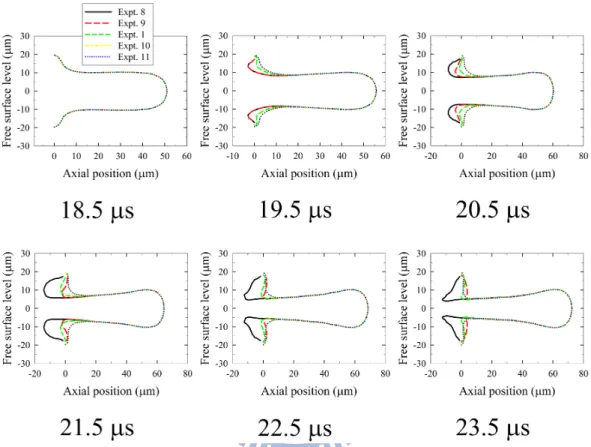
localized volume force induced by surface tension effect. After the period of the backward actuation terminates, the liquid in the nozzle would thus be pulled out again through the effect of the imbalance of surface tension and the inertia of the liquid in the ink-supply channel. The extent of tube invasion by the retracting meniscus and the acceleration of the thinning of the fluid neck increase as We increases [see Fig. 3.9, b
18.5 and 19.5 µs]. Experiment 8, in which the condition of the backward actuation has the same value of We as in experiment 9 but a large working interval, b ∆τb, shows a greater extent of tube invasion and a smaller curvature of the liquid interface, thus causing a larger rate of volume flow of the liquid toward the nozzle outlet. Figure 3.10 shows the temporal variation of the rate of volume flow at the plane of the nozzle entrance. At the end of the backward stroke, the rate of volume flow at the plane of the nozzle entrance is directed toward the nozzle outlet and turns gradually into a still
36
state. As mentioned above, experiment 8 has the rate of volume flow much less than experiment 9 because of the small curvature of the retracting meniscus. Experiment 11 is analogously expected to have a lesser rate of volume flow than experiment 10, as shown in Fig. 3.10. Figure 3.11 shows the variation with experiments of duration of the liquid thread pinching off from the nozzle exit. Experiment 11 seems to have the smallest interval of pinching off. The backward actuation of experiment 11 might proceed through a considerable period in which pinching off of the liquid thread occurs before the rate of volume flow of the liquid toward the nozzle outlet begins because the surface tension is unbalanced. Experiment 8 appears to have large duration of pinching off because the large rate of volume flow toward the nozzle outlet occurs behind the period of the backward stroke, as shown in Fig. 3.10, therefore decelerating the thinning of the fluid neck and prolonging the pinching off. Distinct values of Web cause varied acceleration of the thinning of the fluid neck,
which facilitates the thread pinching off. Various intervals ∆τb of backward stroke
along with various values of Web may cause varied extent of tube invasion, which
obstructs the thread pinching off by inducing the rate of volume flow toward the nozzle outlet beyond the period of backward actuation. Experiments 1, 9 and 10 with different combinations of Web and ∆τb lead to the same duration of the thread