國 立 交 通 大 學
資訊
學院資訊科技(IT)產業研發碩士專班
碩
士
論
文
道路監
控:基於車間通訊之可疑車輛追蹤與回報系
統
Surveillance On-the-Road: A Suspicious Vehicle
Tracking and Reporting System Based on V2V
Communications
研 究
生: 薛坤澤
道路監
控:基於車間通訊之可疑車輛追蹤與回報系統
Surveillance On-the-Road: A Suspicious Vehicle Tracking and
Reporting System Based on V2V Communications
研 究
生 : 薛坤澤
Student: Kun-Ze Syue
指 導 教 授 : 曾煜棋
Advisor: Yu-Chee Tseng
國 立 交 通 大 學
資訊
學院資訊科技(IT)產業研發碩士專班
碩 士 論 文
A Thesis
Submitted to College of Computer Science
National Chiao-Tung University
in Partial Fulfillment of the Requirements
for the Degree of
Master
in
Industrial Technology R & D Master Program on
Computer Science and Engineering
June 2010
Hsinchu, Taiwan, Republic of China
道路監
控:基於車間通訊之可疑車輛追蹤與回報系統
學 生 : 薛坤澤
指 導 教 授 : 曾煜棋
國立交通大學資訊學院資訊科技(IT)產業研發碩士專班
摘
要
由於車載無線存取能力/特定短距通訊 (WAVE/DSRC) 和嵌入式監控系統科技迅速的 發展,已使得車輛監控網路成為可能。車輛監控網路科技將在車輛上,配備影像攝影 機,並用來監控位於道路上的各種事件。在這篇論文中,每台車輛將配備有影像攝影 機,並結合車牌辨識 (LPR) 技術,來做到識別可疑車輛(如:贓車)之目的。此外,亦利 用WAVE/DSRC為車載無線通訊介面,透過車間通訊 (V2V) 的技術,完成協同式可疑 車輛的追蹤和快速回報此發現訊息於道路上最近的警車。特別的是,我們提出一個無 基礎設施 (Infrastructure-less) 的架構,此架構將包括追蹤模組 (Tracking module) 與回 報模組 (Reporting module),此方法架構將設計針對可疑車輛的追蹤與回報處理機制。 對於追蹤模組的功能設計為,在追蹤期間,必要時將把追蹤的工作換手 (Handoff) 至附 近的車輛。此外,透過無需數位地圖 (Digital map) 的路口偵測 (Intersection detection) 機制完成回報到道路上附近的警車;對於回報模組的功能設計為,利用協同式導引回報 訊息至道路上最近警車的方法,以替代常用的氾濫式廣播 (Flooding) 訊息傳遞方式。 而透過網路模擬 (Simulation) 的結果顯示,我們提出的方法架構可以避免不必要的重 廣播 (Rebroadcast) 訊息,並可以有效地節省網路上訊息量的開銷。 關 關 關鍵鍵鍵字字字:::特定短距通訊、車牌辨識、車載監控網路、車載追蹤、車載無線存取。Surveillance On-the-Road: A Suspicious Vehicle Tracking and Reporting
System Based on V2V Communications
Student: Kun-Ze Syue
Advisor: Yu-Chee Tseng
Submitted to College of Computer Science
Computer Science and Engineering
National Chiao-Tung University
ABSTRACT
The rapid progress of Wireless Access in Vehicular Environment/Dedicated Short Range Communication (WAVE/DSRC) and embedded surveillance system technologies has made vehicular surveillance networks possible. The vehicular surveillance network is a technol-ogy where video cameras are deployed on vehicles to monitor various phenomenons on the road. In this paper, each vehicle employs a video camera to identify suspicious vehicles (such as stolen cars) through license plate recognition (LPR) technologies. In addition, WAVE/DSRC-based radio interfaces are used to cooperatively track the identified suspi-cious vehicle and quickly report the discovery to nearby police cars via vehicle-to-vehicle (V2V) communications. In particular, we propose an infrastructure-less framework for suspicious vehicle tracking and reporting, which consists of a tracking module and a re-porting module. The tracking module can handoff the tracking job to neighboring vehicles as necessary and detect intersection for reporting to nearby police cars without additional digital map. The reporting module can guide reporting messages to the nearest police car instead of flooding. Simulation results show that the proposed framework outperforms ex-isting works, which can significantly reduce the control overhead by avoiding large amount of unnecessary rebroadcasts.
Keywords: Dedicated Short Range Communications, License Plate Recognition, Vehicu-lar Surveillance Networks, Vehicle Tracking, Wireless Access in VehicuVehicu-lar Environments.
誌
誌
誌
謝
謝
謝
首先我要誠摯地感謝我的指導老師曾煜棋教授,這兩年來的指導與鼓勵,並提供 良好的研究環境與充足的實驗設備, 讓我得以順利完成此篇論文,並取得碩士學位。 同時也要感謝口試委員王素華、王文良、黃貞芬教授給予碩論方面的指正和建 議。 另外,我也要由衷地感謝博後陳烈武學長,在本篇論文上面的協助與建議。在彼 此分工與合作下,更讓我有參與發表 兩篇國外Conference Demo Papers的機會,豐富 了求學間的學經歷。 我也要感謝實驗室一起打拼的研究同儕們,讓我們常在課後閒暇之餘,有著美好 的回憶與趣事。另外,也要由衷地感 謝實驗室裡的每位學長、學姊、學弟妹的鼓勵與 幫助。 最後,我要感謝家人對我的期許與幫助,讓我得以寬心去完成碩士學位。僅以此 篇論文獻給我摯愛的家人。 在此向你們獻上我最誠摯的謝意。 薛坤澤 謹識於 國立交通大學資訊學院資訊科技 (IT) 產業研發碩士專班 中 華 民 國 九 十 九 年 六 月Contents
書名頁 . . . i 中文摘要 . . . ii 英文摘要 . . . iii 誌謝 . . . iv Contents . . . vList of Tables . . . vii
List of Figures . . . viii
1. Introduction . . . 1
2. Problem Definition . . . 3
3. Suspicious Vehicle Tracking and Reporting Framework . . . 5
3.1 Tracking Module . . . 6
3.1.1 Tracking Handoff Scheme . . . 7
3.1.2 Intersection Detection Scheme . . . 7
3.2 Reporting Module . . . 10
3.2.1 Rebroadcast Decision Scheme . . . 11
3.2.2 Intersection-guiding Search Scheme . . . 12
3.2.3 Memory-based Backoff Scheme . . . 14
4. Performance Evaluation . . . 17
5. Prototype Implementation . . . 22
5.2 Camera Module . . . 24 5.3 GPS Receiver . . . 24 5.4 WAVE/DSRC Radio . . . 24 5.5 CO2 Sensor . . . 25 5.6 3G Module . . . 25 5.7 Demonstration . . . 25 6. Conclusion . . . 27 Bibliography . . . 28
List of Tables
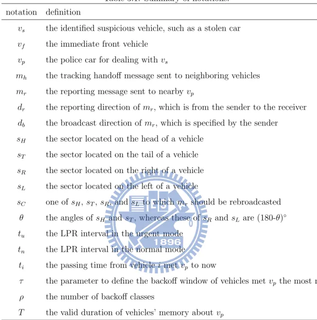
3.1 Summary of notations. . . 6 3.2 Default EDCA parameter set. . . 15 4.1 Simulation parameters . . . 18
List of Figures
2.1 System architecture for suspicious vehicle tracking and reporting. . . 3
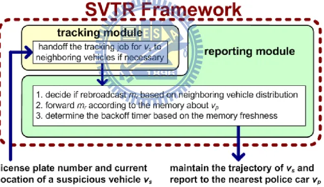
3.1 Components of the proposed framework. . . 5
3.2 Handoff the tracking job to neighbor vehicles if necessary. . . 8
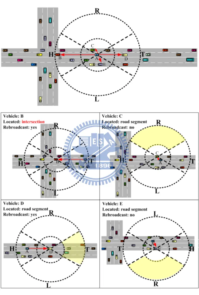
3.3 Rebroadcast decision based on the neighboring vehicle distribution. . . 9
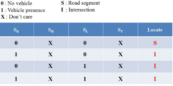
3.4 Summary definitions of intersection detection . . . 10
3.5 Reporting the suspicious vehicle discovery to nearby police cars. . . 12
3.6 Procedures of the intersection-guiding search scheme. . . 13
4.1 Urban topology used in the experiments. . . 17
4.2 Comparison of total number of reporting messages. . . 18
4.3 Comparison of packet collision rate. . . 19
4.4 Comparison of average reporting delay to the police car. . . 20
4.5 Handoff success rate under different number of vehicles and tracking hand-off duration. . . 21
5.1 Building blocks of VS3. . . 22
5.2 Hardware components of VS3. . . 23
Chapter 1
Introduction
The rapid progress of Wireless Access in Vehicular Environment/Dedicated Short Range Communication (WAVE/DSRC) and embedded surveillance system technologies has made vehicular surveillance networks possible. The vehicular surveillance network is a technology where video cameras are deployed on vehicles to monitor various phenomenons on the road, such as vehicle security [1], brake warning [2], and urban monitoring [3]. In this work, we focus on tracking suspicious vehicles and reporting to nearby police cars without costly infrastructures. Most existing works for these two purposes rely on roadside infrastructures and sensors [4–7].
For tracking purposes, reference [4] presents an architecture for vehicle tracking sys-tems using wireless sensor technologies. Roadside units (RSUs) are installed along roads to continuously keep tracking vehicles at regular intervals. These RSUs are connected to the underlying wired infrastructure to receive queries from the central server and reply back with the necessary information. Reference [5] presents a wireless local area network (WLAN)-based real time system for vehicle localization. The proposed solution uses a neural network trained with a map of received power fingerprints from WLAN Access Points (APs) surrounding the vehicle. In these two works, however, a large number of RSUs and WLAN APs must be installed on the roadside to provide target information and received signal strengths to vehicles, respectively. Reference [7] proposes a smart parking scheme in VANETs, which includes the stolen vehicle tracking. When the thief drives the stolen vehicle along a road, all pass-by RSUs can detect the parking beacon sent from the moving vehicle. According to the parking lot’s identifier in the beacon, it
can report the position of the stolen vehicle to the parking lot. But as the same with [4] and [5], the stolen vehicle tracking is also achieved by the deployment of RSUs along roads.
For reporting purposes, reference [6] proposes a searching strategy called ANTS to locate a desire vehicle close to the query user, which is based on the lost ant searching for its nest. ANTS is employed in ShanghaiGrid [8] consisted of a large number of local nodes installed at crossroads, which is responsible for storing vehicle information and accepting queries. However, deploying such local nodes on each intersection requires a dramatic number of RFID readers and wireless APs and thus is costly. More importantly, it may not be practical to construct infrastructure in suburban and rural areas.
In particular, we propose an infrastructure-less framework for suspicious vehicle tracking and reporting, which consists of a tracking module and a reporting module. The tracking module can handoff the tracking job to neighboring vehicles if necessary and detect intersection for reporting to nearby police cars without digital map informa-tion. The reporting module can find the nearest police car at low message cost. It does not rely on costly roadside infrastructures and only relies on vehicle-to-vehicle (V2V) communications. On the other hand, traditional surveillance and tracking systems rely on roadside cameras for video recording. There are two problems associated with such solutions. First, it requires huge efforts to distinguish targets from many other candi-dates. Second, since targets are not predefined, the recorded images are usually not clear enough. Further, the volume of videos could be huge, thus requiring a lot of labors.
The rest of this paper is organized as follows. Chapter 2 defines the suspicious vehicle tracking and reporting problem. Chapter 3 describes our framework, which consists of a tracking module and a reporting module. Simulation results are presented in Chapter 4. Chapter 5 shows the prototype implementation. Finally, Chapter 6 concludes the paper.
Chapter 2
Problem Definition
Figure 2.1: System architecture for suspicious vehicle tracking and reporting. Figure 2.1 shows the system architecture for suspicious vehicle tracking and report-ing. We consider vehicles on the roads that form vehicular surveillance networks via V2V communications. Each vehicle is equipped with a GPS receiver and a video camera. The GPS receiver serves to provide vehicle’s own position. The video camera is to take/record the license plate pictures/videos of the immediate front vehicle. With license plate recog-nition (LPR) technologies, each vehicle can recognize the license plate number of its front vehicle. For identifying suspicious vehicles, recognized license numbers are compared with the suspicious vehicle database provided by the police department. Each vehicle has an
IEEE 802.11p [9] radio interface operating in the WAVE mode, which can dramatically reduces the connection setup overhead by discarding all association and authentication procedures. As long as vehicles operate in the same channel and use the wildcard Basic Service Set Identification (BSSID) composed of all ”1s” in a 48-bit long field, they can immediately communicate with each other upon encounter on the road without having to join a BSS. Periodical beacons are used to obtain the IDs and positions of neighboring vehicles. In addition, TTL (time to live) is indicated in broadcasting messages to limit the number of their transmissions in vehicular surveillance networks.
The suspicious vehicle tracking and reporting (SVTR) problem is defined as follow. Each radio interface has a fixed transmission range of R. Each vehicle i has to identify whether the immediate front vehicle vf is a suspicious vehicle vs or not. There are two
modes for LPR on the road that i recognizes vf’s license plate number every tu and
tn seconds in the urgent mode and the normal mode, respectively. Before vs has been
identified, i recognizes the license plate number of vf in the normal mode. Once vf is
identified as vs, i will report this discovery to nearby police cars vp and switch to the
urgent mode to continuously recognize the license plate number of vf to keep tracking
vs. If vs is not in front of i due to changing its lane or direction, the tracking job will be
handoff from i to i’s neighboring vehicle immediate behind vs.
Our goal is to design an efficient protocol for vehicles to cooperatively track the identified vs. It addition, during the tracking process, we need to report the current
position of vs to vp. Such reporting messages mr should be guided to the nearest vp and
delivered through multi-hop forwarding. Therefore, vp received these mr can reconstruct
the trajectory of vs and arrive at the position of vs as soon as possible to take further
Chapter 3
Suspicious Vehicle Tracking and
Reporting Framework
Figure 3.1: Components of the proposed framework.
In this section, we propose an infrastructure-less framework to solve the SVTR prob-lem, which consists of a tracking module and a reporting module, as shown in Figure 3.1. First, to keep tracking the identified vs, we propose tracking handoff and intersection
detection schemes in Section 3.1. Second, to efficiently deliver reporting messages about vs to the nearest vp, rebroadcast decision,intersection-guiding search, and memory-based
adopted in this section.
Table 3.1: Summary of notations. notation definition
vs the identified suspicious vehicle, such as a stolen car
vf the immediate front vehicle
vp the police car for dealing with vs
mh the tracking handoff message sent to neighboring vehicles
mr the reporting message sent to nearby vp
dr the reporting direction of mr, which is from the sender to the receiver
db the broadcast direction of mr, which is specified by the sender
sH the sector located on the head of a vehicle
sT the sector located on the tail of a vehicle
sR the sector located on the right of a vehicle
sL the sector located on the left of a vehicle
sC one of sH, sT, sR, and sL to which mr should be rebroadcasted
θ the angles of sH and sT, whereas these of sR and sL are (180-θ)◦
tu the LPR interval in the urgent mode
tn the LPR interval in the normal mode
ti the passing time from vehicle i met vp to now
τ the parameter to define the backoff window of vehicles met vp the most recently
ρ the number of backoff classes
T the valid duration of vehicles’ memory about vp
3.1
Tracking Module
ing vehicle immediate behind vs due to vs changes its lane or direction. In addition, for
reconstructing the trajectory of vs, we design an intersection detection scheme to report
the current position of vs to vp on each intersection during the tracking process.
3.1.1
Tracking Handoff Scheme
If vehicle i detects its vf as vs in the normal mode, i will switch to the urgent mode to
keep tracking vs. Once i can not detect vsin the urgent mode, i will broadcast a tracking
handoff message mh to neighboring vehicles. Vehicles received mh will switch from the
normal mode to the urgent mode for detecting the missed vs. The neighboring vehicle
j detected vs will take over the tracking job from i, and other neighboring vehicles will
switch to the normal mode after the predefined period from the urgent mode. Similarly, once j can not detect vs in the urgent mode, j will repeat the above procedures taken
by i. For example in Figure 3.2, A is a tracking vehicle in the urgent mode and B is a suspicious vehicle tracked by A. Once A can not detect B in the urgent mode, A will broadcast mh to C and D. C and D will switch from the normal mode to the urgent
mode for detecting B. On one hand, since C has detected B, the tracking job is handoff from A to C. On the other hand, after the predefined period in the urgent mode, D will switch back to the normal mode.
3.1.2
Intersection Detection Scheme
As shown in Figure 3.3, the outer circle is the transmission range of each vehicle i and the inner circle is a controlled parameter based on the vehicle density to filter nearby vehicles. The transmission range is divided into four sectors according to i’s driving direction. The head, tail, right, and left of i are the sectors sH, sT, sR, and sL,
respectively. Angles of sH and sT are defined as θ◦ whereas those of sR and sL are defined
as (180-θ)◦. Note that the inner circle area is not included in all sectors.
Since every vehicle periodically sends a beacon message contained its position infor-mation, i can maintain the neighboring vehicle distribution in its transmission range. In addition to position information, vp also announces its identifier in its beacon message.
Figure 3.4: Summary definitions of intersection detection
Thus, other vehicles met vp can record the time and position information from vp’s
bea-con message. Since all positions of i’s neighboring vehicles can be obtained from received beacon messages, i can determine whether there are neighboring vehicles in its sH, sT,
sR, and sL.
By checking if each sector has neighboring vehicles, i can detect that itself is on intersection or road segment. For example, if there is no neighboring vehicle in sRand sL,
it implies that i is located on road segment. Conversely, if there are neighboring vehicles in either sR or sL, it implies that i is located on intersection. For example in Figure 3.3,
vehicle A, C, D, and E is on road segment whereas vehicle B is on intersection. Note that the corner (i.e., there are neighboring vehicles in two adjacent sectors) will also be detected as intersection in our scheme since it consists of two road segments with different directions.Figure 3.4 shows the Summary definitions of intersection detection.
to an ambulance car. Obviously, an ambulance car close to the accident location is more preferable. Flooding is an intuitive search scheme that can always find the nearest vp.
However, it produces a huge amount of network traffic and thus its scalability is low. To reduce the control overhead for reporting mr to nearby vp, we design rebroadcast
decision, intersection-guiding search, and memory-based backoff schemes to minimize the number of mr rebroadcasts, where mr contains the discover’s ID, vs’s position and license
number, and a sequence number.
3.2.1
Rebroadcast Decision Scheme
In this scheme, vehicles decide whether rebroadcast mr according to their positions
and mr’s reporting direction dr. The rebroadcast decision is made as follows.
1. Once vehicle i identifies the license plate number of vs, i will immediately send mr
to nearby vp. When vehicle j receives mr sent by i, j first detects its location type
according to its neighboring vehicle distribution. If j is located on intersection, it will rebroadcast mr immediately. On the contrary, if j is located on road segment,
it will detect dr based on the sender’s position and check whether the corresponding
sector sC for dr has neighboring vehicles. If j’s sC for dr has neighboring vehicles,
mrwill be rebroadcasted by j. Otherwise, mrwill be discarded to avoid unnecessary
rebroadcasts since there is no neighboring vehicle in j’s sC for dr. For example in
Figure 3.3, the sender A is located on sT of B so that dr is from sT to sH and thus
sC for dr is sH.
2. Similarly, after other vehicles receive mr from i, they first detect their location
types. On one hand, for the vehicle located on intersection, it will rebroadcast mr
to the vehicles on all its sectors. On the other hand, for the vehicle located on road segment, it decides to rebroadcast according to whether there are neighboring vehicles in its sC for dr. For example in Figure 3.3, based on the current position and
dr, vehicle C and E decide not to rebroadcast mr because there is no neighboring
vehicle in their sRs whereas vehicle D decides to rebroadcast mr since D’s sT has
3.2.2
Intersection-guiding Search Scheme
Figure 3.5: Reporting the suspicious vehicle discovery to nearby police cars. Based on the above rebroadcast decision scheme, we further develop an intersection-guiding search scheme, which mr is guided to the nearest vp as follows.
1. At the beginning in Figure 3.5, vehicle A identifies vs and reports mr to the nearest
vp. There are four intersections traveled by mr from A. Vehicle B is located on
Therefore, each vehicle located on the first intersection receiving B’s rebroadcasted mr will decide its db by itself.
3. On the second intersection in Figure 3.6, vehicle C can detect that mr is from sH
(i.e., from B to C) and that C itself is located on intersection. In particular, C has met vp 10 seconds ago. So C guides mr to its sL, which is closest to the recorded
position of vp 10 seconds ago. Thus, only the neighboring vehicles in C’s sL will
try to rebroadcast mr from C. Those neighboring vehicles in other three sectors
will discard mr immediately because db of mr has been specified (i.e., denoted by
”broadcast to: sL”). Note that db specified by C is the related direction between
C’s position and the past position of vp in C’s memory.
4. On the third intersection in Figure 3.6, vehicle E can detect that mr is from sH
(i.e., from D to E) and that E itself is located on intersection. Based on the C’s memory for vp, mr should be rebroadcasted to sR of E. However, E has met vp 5
seconds ago, which is more up-to-date than C. So mr will be guided to sL according
to E’s memory for vp. Therefore, vp can be found without rebroadcasting mr to
other road segments on intersection.
Since db can be guided on intersection by vehicles’ memory for vp, the flooding of
mr can be intelligently avoided and converted to an unidirectional forwarding. Thus, the
number of rebroadcasted mr can be significantly reduced by the proposed
intersection-guiding search scheme, which also can minimize the reporting delay caused by message collisions.
3.2.3
Memory-based Backoff Scheme
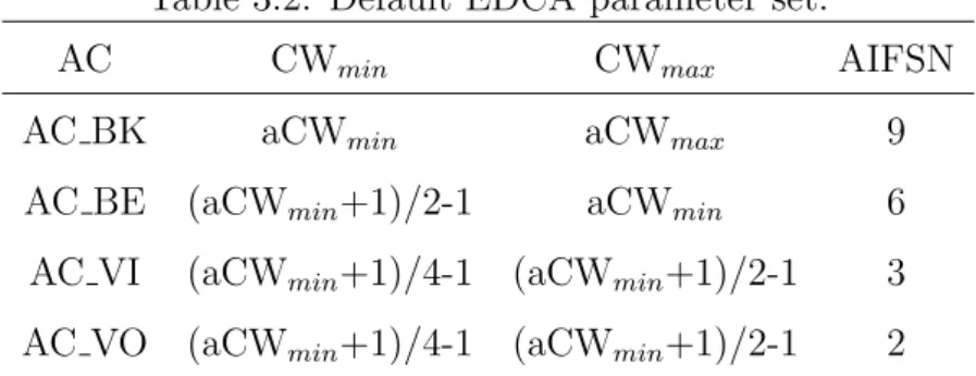
Table 3.2: Default EDCA parameter set.
AC CWmin CWmax AIFSN
AC BK aCWmin aCWmax 9
AC BE (aCWmin+1)/2-1 aCWmin 6
AC VI (aCWmin+1)/4-1 (aCWmin+1)/2-1 3
AC VO (aCWmin+1)/4-1 (aCWmin+1)/2-1 2
is a fixed waiting time in unit of slot, whereas the backoff timer is a random waiting time selected from a Contention Window (CW). The CW size is initially set to CWmin
and doubled until reaching CWmax after each transmission collision. The default EDCA
parameter set of IEEE 802.11p is shown in Table 3.2. In our scheme, mr is assigned to
AC VO with the smallest AIFSN and a memory-based backoff timer.
To reduce the number of mr rebroadcasts, we design a memory-based backoff scheme
to make the receiver met vp the most recently be the first rebroadcasting guider without
any central control. When vehicle i receives mr, i first decides to rebroadcast it or not. If
i decides to rebroadcast mr, i will be assigned a backoff timer based on the passing time
ti from i met vp to now. If i never met vp before, ti will be set to ∞. Thus, i with the
smaller ti can get the smaller backoff timer, which is shown as follows:
BTi = [0, 2τ +1− 1] 0 < t i ≤ 1ρT [2τ +1, 2τ +2− 1] 1 ρT < ti ≤ 2 ρT .. . [2τ +ρ−1, 2τ +ρ− 1] ρ−1ρ T < ti ≤ ∞ ,
where τ is the parameter to define the backoff timer of vehicles met vp the most recently,
ρ is the number of backoff classes, and T is the valid duration of vehicles’ memory about vp. Thus, receivers with the more up-to-date memory for vp can easily select the smaller
backoff timers so that one of them can be the first rebroadcasting guider. In addition, an implicit acknowledgement (ACK) strategy is adopted to eliminate redundant mr, in
which the reception of mr with the same sequence number serves as an implicit ACK. On
receiving an implicit ACK, vehicles received mr do not need to rebroadcast it. There is
no retransmission for any collided mr from a rebroadcasting guider. So mr with the same
sequence number will not be retransmitted at any rebroadcasting guider even it collides with other control messages or data packets. In order to prevent that no rebroadcasting
guider successfully rebroadcasts mr, the backoff timer of the sender is set to 2τ +ρ. Once
the sender backs off to 0, it sends mr with a new sequence number to differentiate an
implicit ACK.
From the above expression, it is clear that the backoff timer is chosen based on the memory for vp of the receiver. Vehicle i with the smallest ti may choose the smallest BTi
and thus has a chance to rebroadcast and guide mr earlier than all the other receivers.
When other receivers detect the rebroadcasting of mr with the same sequence number,
all of them refrain from rebroadcasting. In this way, the memory-based backoff scheme efficiently reduces the number of mr rebroadcasts as well as the probability of message
Chapter 4
Performance Evaluation
Figure 4.1: Urban topology used in the experiments.
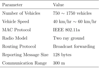
The proposed suspicious vehicle tracking and reporting framework is implemented in the QualNet 5.0 [10] simulator with necessary modifications. The performance is evaluated in a 5km2 urban area, which each building block is 1km2, as shown in Figure 4.1. Vehicles are uniformly placed on each road segment and their directions are randomly selected on each intersection. Basic parameters used in our simulation are summarized in Table 4.1. We set tu = 1 s, tn = 10 s, τ = 1, ρ = 3, and T = 30 s. In the following evaluation,
total number of reporting messages and reporting delay to the police car are addressing in the comparison of the proposed framework, the flooding scheme, and the intelligent broadcast scheme [11].
Figure 4.2 illustrates the total number of reporting messages under different number of vehicles. We set the total number of vehicles as 750, 1000, 1250, 1500, and 1750. Both
Table 4.1: Simulation parameters Parameter Value
Number of Vehicles 750 ∼ 1750 vehicles Vehicle Speed 40 km/hr ∼ 60 km/hr MAC Protocol IEEE 802.11a
Radio Model Two ray ground Routing Protocol Broadcast forwarding Reporting Message Size 128 bytes
the suspicious car and the police car are randomly selected. From Figure 4.2, we can observe that our framework has the lowest number of reporting messages. This is because our reporting module may guide reporting messages on each intersection by the memory of vehicles for the police car, which only one road segment is needed to be rebroadcast. On the contrary, flooding and intelligent broadcast will rebroadcast all road segments on each intersection so that their total numbers of reporting messages increase with the total number of vehicles.
Figure 4.3: Comparison of packet collision rate.
Figure 4.3 shows the packet collision ratio under different number of vehicles on the roads, which the suspicious car and the police car are randomly selected. From Figure 4.3, we can observe that the packet collision rate of our framework is lower than those of intelligent broadcast and flooding. This is because flooding broadcasts many reporting messages so that the probability of transmitting packets at the same time becomes higher, as well as intelligent broadcast. The situation becomes worse when the total number of vehicles increases. On the contrary, our framework only needs to transmit reporting packets to those vehicles closer to the police car, which the number of vehicles in one road segment is lower than the number of vehicles in all road segments on each intersection. In addition, the memory-based backoff scheme in our framework further reduces the packet
collision rate.
Figure 4.4: Comparison of average reporting delay to the police car.
Figure 4.4 shows the average reporting delay to the police car for various numbers of vehicles on the roads. As the same with Figure 4.2 and Figure 4.3, both the suspicious car and the police car are randomly selected. In Figure 4.3, our framework has the similar reporting delay with intelligent broadcast and flooding as the total number of vehicles increases. Since the proposed framework only needs to rebroadcast reporting messages to one road segment instead of all on intersection, it can produce the similar reporting delay while keeping the reporting cost low. On the other hand, Figure 4.5 shows the handoff success rate under different number of vehicles and handoff tracking duration, which varied from 750 to 1750 and from 5 to 30 seconds, respectively. The handoff success rate increases from 36% to 97% as the total number of vehicles and handoff tracking duration increase.
Figure 4.5: Handoff success rate under different number of vehicles and tracking handoff duration.
both avoid the transmission of reporting messages wasting bandwidth due to unneces-sary rebroadcasts and prevent reporting messages from collision caused by serious packet contention.
Chapter 5
Prototype Implementation
through the UART interfaces. Below, we describe implementation details.
Figure 5.2: Hardware components of VS3.
5.1
Microprocessor
The microprocessor in the car unit is an ARM9 board (Mini2440 [12]) with a 3.5” TFT LCD as shown in Figure 5.2(a), which has a 400MHz 32-bit RISC integer processor (ARM920T [13]), 64MB SDRAM, 64MB Nand Flash, Camera Interface, three serial ports, a 10/100M Ethernet RJ-45, and built-in microphone. In particular, Mini2440 can run embedded Linux and WinCE to develop diverse applications. During the development stage, Linux with an arm-linux-gcc compiler is installed first. Then, the ARM9 board is connected to a PC through the RS-232 interface.
5.2
Camera Module
Figure 5.2(d) shows the camera module CAM130, a CMOS optical sensor. It re-ceives snapshot commands from Mini2440 and takes full-resolution pictures to Mini2440 through the Camera Interface. Similar to the CO2 Sensor, a character device (such as
”/dev/camera”) in Linux must be opened to get the video data. An array is declared to store data from the character device. Through the Linux framebuffer mechanism, the video data can be copy to the mapped memory space and displayed on the TFT screen.
To output the video data captured from the camera to an image file, the jpeg library, libjpeg, is linked to the executable program. It also transforms the 16-bit color images to the 24-bit color format (RGB888). Moreover, the color compensation of RGB bytes is adopted to make images clearer.
5.3
GPS Receiver
The GPS module is implemented by uPatch300 [14] with the embedded GPS antenna as shown in Figure 5.2(e), which follows NMEA (National Marine Electronics Associa-tion) 0183 protocol. It uses SiRFstarIII chip with high sensitivity to provide geographic information to locate positions of vehicles.
5.4
WAVE/DSRC Radio
The WAVE/DSRC module is implemented by ITRI WAVE Communication Unit (IWCU [15]), which is connected by Ethernet RJ-45 with Mini2440. It has two IEEE 802.11p [9] interfaces and one Ethernet connector. Vehicular applications developed
5.5
CO
2Sensor
The CO2 module has a H-550EV CO2 sensor [16] integrated with Jennic JN5139
[17], which is mounted to Mini2440 via an UART interface. Our prototype is shown in Figure 5.2(b). The CO2 sensor module has 0∼5,000 ppm measurement range and
±30ppm accuracy. JN5139 has a 16MIPs 32-bit RISC processor, a 2.4GHz IEEE 802.15.4-compliant transceiver, 192kB of ROM, and 96kB of RAM. In particular, JN5139 allows the flexibility of supporting mesh networking and packet routing inside a vehicle. To obtain sensing data from the CO2 sensor, a character device (such as ”/dev/ttySAC#”)
in Linux is opened to read/write data from/to the serial port.
5.6
3G Module
We adopt the Wavecom Q2403A GSM/GPRS/CDMA module as shown in Fig-ure 5.2(c), which is controlled by Mini2440 via AT commands. It performs SMS, MMS, and video calls as instructed by the ARM9 board. To send a short message, AT commands are issued to control GSM/GPRS modem.
5.7
Demonstration
For license plate recognition (LPR), we integrate a software with the following func-tions: plate localization, plate orientation and sizing, normalization and edge detection, character segmentation, and optical character recognition. For suspicious car tracking and reporting, we demonstrate that the license plate picture of a vehicle is taken in a model car as shown in Figure 5.3(a), and it has been recognized as a suspicious vehicle as shown in Figure 5.3(b). Figure 5.3(c) and Figure 5.3(d) show our prototyping system set up in a real car and a suspicious vehicle tracking scenario, respectively.
Chapter 6
Conclusion
This paper integrates WAVE/DSRC communications into surveillance technologies to support suspicious vehicle tracking and reporting applications without costly roadside infrastructures. Vehicles on the road form a vehicular surveillance network for tracking a suspicious vehicle and reporting the discovery to the nearest police car. We propose an infrastructure-less framework for suspicious vehicle tracking and reporting based on V2V communications, which consists of a tracking module and a reporting module. The tracking module can handoff the tracking job to neighboring vehicles if necessary and detect intersection for reporting to nearby police cars without digital map information. The reporting module can find the nearest police car at low message cost. The proposed framework can significantly reduce the control overhead by avoiding large amount of unnecessary rebroadcasts.
Bibliography
[1] L.-W. Chen, K.-Z. Syue, and Y.-C. Tseng, “VS3: A Vehicular Surveillance and
Sensing System for Security Applications,” in IEEE International Conference on Mobile Ad-hoc and Sensor Systems (IEEE MASS 2009), Oct. 2009.
[2] P. Thammakaroon and P. Tangamchit, “Adaptive Brake Warning System for Auto-mobiles,” in 8th International Conference on ITS Telecommunications (ITST 2008), pp. 204–208, Oct. 2008.
[3] U. Lee, E. Magistretti, M. Gerla, P. Bellavista, and A. Corradi, “Dissemination and harvesting of urban data using vehicular sensing platforms,” IEEE Transactions on Vehicular Technology, vol. 58, pp. 882–901, Feb. 2009.
[4] K. G. Aravind, T. Chakravarty, M. G. Chandra, and P. Balamuralidhar, “On the ar-chitecture of vehicle tracking system using wireless sensor devices,” in International Conference on Ultra Modern Telecommunications & Workshops (ICUMT 2009), pp. 1–5, Oct. 2009.
[5] M. Caceres, F. Sottile, and M.A. Spirito, “WLAN-Based Real Time Vehicle Locating System,” in The 69th IEEE Vehicular Technology Conference (IEEE VTC-Spring 2009), pp. 1–5, Apr. 2009.
[6] M. Li, H. Zhu, Y. Zhu, and L. M. Ni, “ANTS: Efficient Vehicle Locating Based on Ant Search in ShanghaiGrid,” IEEE Transactions on Vehicular Technology, vol. 58, pp. 4088–4097, Oct. 2009.
[7] R. Lu, X. Lin, H. Zhu, and X. Shen, “SPARK: A New VANET-Based Smart Park-ing Scheme for Large ParkPark-ing Lots,” in The 28th IEEE Conference on Computer Communications (IEEE INFOCOM 2009), pp. 1413–1421, Apr. 2009.
[10] QualNet, “http://www.scalable-networks.com/products/qualnet/,”
[11] S. Biswas, R. Tatchikou, and F. Dion, “Vehicle-to-Vehicle Wireless Communication Protocols for Enhancing Highway Traffic Safety,” IEEE Communications Magazine, vol. 44, pp. 74–82, Jan. 2006.
[12] FriendlyARM, Mini2440, “http://www.friendlyarm.net,”
[13] ARM, ARM920T, “http://www.arm.com/products/CPUs/ARM920T.html,” [14] Fastrax, uPatch300, “http://www.fastrax.fi,”
[15] ITRI WAVE Communication Unit, “http://www.itri.org.tw,”
[16] H-550EV CO2 Sensor Module,
“http://www.co2sensor.co.kr/new/eng/ndir-co2-sensor-module-h550ev.htm,”