97
碩
士
論
文
進
階
性
無
線
網
路
媒
介
存
取
控
制
與
路
由
協
定
技
術
電國 信立 工交 程通 學大 系學 碩電 士機 班學 院國 立 交 通 大 學
電信工程學系
碩 士 論 文
進階性無線網路媒介存取控制與路由協
定技術
Advanced Medium Access Control and
Routing Techniques for Wireless
Networks
研究生:黃瑜智
指導教授:方凱田
國 立 交 通 大 學
電信工程學系
碩 士 論 文
進階性無線網路媒介存取控制與路由協
定技術
Advanced Medium Access Control and
Routing Techniques for Wireless
Networks
研究生:黃瑜智
指導教授:方凱田
進階性無線網路媒介存取控制與路由協定技術
Advanced Medium Access Control and Routing Techniques for
Wireless Networks
研究生:黃瑜智
Student:Yu-Tzu Huang
指導教授:方凱田
Advisor:Kai-Ten Feng
國立交通大學
電信工程學系碩士班
碩士論文
A Thesis
Submitted to Department of Communication Engineering
College of Electrical and Computer Engineering
National Chiao Tung University
in Partial Fulfillment of the Requirements
for the Degree of
Mater of Science
in Communication Engineering
June 2008
Hsinchu, Taiwan, Republic of China
進階性無線網路媒介存取控制與路由協定技術
學生:黃瑜智 指導教授:方凱田
國立交通大學電信工程學系碩士班
摘 要
由於近年無線區域網路技術的興起,使得提高單位時間內有效的資
料傳輸量成為很重要的議題。IEEE 802.11n 中,訊框堆合為改善整體傳
輸效率技術之一。為了使訊框堆合能有效使用於非理想傳輸通道中,錯
誤重傳機制提供了可靠傳輸的解決辦法。在此篇論文中,針對選擇性訊
框重傳以及混合式選擇性訊框重傳配合訊框堆合技術進行效能分析。混
合式選擇性訊框重傳技術,利用直接錯誤更正技術,將發生錯誤之訊框
直接更正,進而降低重傳訊框時所耗費的時間並提高了有效傳輸資料量。
結果我們可以發現,當處於雜訊環境中,混合式選擇性訊框重傳機制配
合訊框堆合技術,可以達到大幅提高有效資料傳輸量的目的。 論文的
第二部份,針對無線網路中的群播協定進行研究與設計。當處於無線環
境中,由於群播協定中常需要轉傳點以傳送資料至特定群組成員。而相
同的資料封包,常存在有多餘的轉傳點傳送。若以省能點觀點角度思考,
如何節省轉傳點的數量為實際面臨的問題,此篇論文對此問題提出試誤
性的解決辦法,並實際利用嵌入式平臺作為演算法設計之系統。
Advanced Medium Access Control and Routing Techniques for Wireless
Networks
Student:Yu‐Tzu Huang
Advisor:Kai‐Ten Feng
Department of Communication Engineering
National Chiao Tung University
Abstract
The next generation wireless local networks (WLANs) with enhanced throughput performance have attracted significant amounts of attention in recent years. Based on the IEEE 802.11n standard, frame aggregation is considered one of the major factors to improve the system performance of WLANs from the medium access control (MAC) perspective. In order to fulfill the requirements of the high-throughput performance, feasible design of automatic retransmission request (ARQ) mechanisms is considered important for providing reliable data transmission. However, none of the existing retransmission schemes is specifically designed under high throughput requirements. In this paper, two ARQ schemes are proposed to consider the effect from frame aggregation for the enhancement of network throughput. An aggregated selective repeat ARQ (ASR-ARQ) algorithm is proposed, which incorporate the selective repeat ARQ scheme with the consideration of frame aggregation. On the other hand, the aggregated hybrid ARQ (AH-ARQ) mechanism is proposed to further enhance the throughput performance by adapting the forward error correction (FEC) scheme. The proposed AH-ARQ algorithm is considered as a MAC-defined retransmission scheme by exploiting the Reed- Solomon block code.
The analytical models for both the ASR-ARQ and the AH-ARQ algorithms are established in this paper, where the scenarios with and without interfering stations are analyzed. Simulations are also conducted to validated and compare the proposed ARQ mechanisms with other existing schemes based on the service time distribution. It will be shown in the numerical evaluation that the proposed AH-ARQ algorithm outperforms the other retransmission schemes owing to its effective utilization of the FEC mechanism.
In the second part of this paper, we focus the topic on the implementation and design of a multicast routing protocol. It is known that how to provide low energy consumption and high
packet delivery ratio are considered the major issues in the protocol design for the wireless multihop networks. The main focus of this part is to reduce the number of data transmissions such that the energy consumption can be decreased. In the wired networks, the Steiner-Tree is regarded as an optimal approach to construct the multicast structure for specific senders and receivers. However, it is considered an NP-Hard problem for achieving the minimum cost multicast tree under the wireless broadcast environment.
In this paper, an Energy-Conserving Multicast Routing (ECMR) protocol is proposed as a heuristic scheme to reduce the number of relaying nodes for the construction of the multicast mesh. Moreover, the proposed algorithm is implemented on an ARM-based embedded platform for performance evaluation. Comparing with the existing multicast routing protocol, the experimental results show that the proposed ECMR scheme can provide better energy conservation while the packet delivery ratio is still preserved.
誌 謝
兩年的研究所生活在這本論文完成的同時,也畫上了句點。首先
要感謝指導教授方凱田老師,在研究的過程中提供許多的建議,固定
的討論讓自己的構思能夠更完備,也從實驗室定期的報告訓練中獲益
良多。同時感謝交通大學電子系黃經堯教授和資工系趙禧綠教授,撥
空來參加口試並給予很多實質的建議,使得論文更趨完整。
感謝給予我無代價支持的家人,分享生活中的喜更分享生活中的
苦,家人讓我知道永遠都會有人在支持我。感謝實驗室的學長學弟們,
仲賢、昭霖、文炫、文俊、裕彬、育群、柏軒、信龍、林志、柏泰。
你們的陪伴和支持讓我有勇氣繼續往人生下個階段挑戰,你們的肯定
和教導讓我知道自己的無限可能。
黃瑜智 謹誌 于交通大學 2008/06
Contents
Chinese Abstract . . . I
English Abstract . . . II
Foreword . . . IV
Contents . . . V
List of Figures . . . VIII
I Performance Analysis of MAC Defined Hybrid ARQ Scheme for Next Generation
Wireless Networks 1
1 Introduction 2 2 Proposed Automatic Retransmission reQuest Mechanisms 5 2.1 Frame Aggregation/De-aggregation of IEEE 802.11n MAC Protocol . . . 5 2.2 Proposed Aggregated Selective Repeat (ASR) ARQ Scheme . . . 7
2.3 Proposed Aggregated Hybrid (AH) ARQ Scheme . . . 8
2.3.1 FEC Mechanism of AH-ARQ Scheme . . . 8
2.3.2 Retransmission Mechanism of the AH-ARQ Scheme . . . 11
3 System Models 13 3.1 Queuing Model of Frame Aggregation . . . 13
3.2 Service Models . . . 14
4.1 Modeling of Service Time Distribution of Proposed ASR-ARQ Scheme . . . 17
4.2 Modeling of Service Time Distribution of Proposed AH-ARQ Scheme . . . 22
4.3 Iteration Algorithm for Proposed ARQ Schemes . . . 25 5 Performance Analysis of Proposed ARQ Schemes with Existence of Interfering Stations 26
5.1 Modeling of Service Time Distribution of Proposed ASR-ARQ Scheme with Contending Stations . . . 26
5.2 Modeling of Service Time Distribution of Proposed AH-ARQ Scheme with Contending Stations . . . 29
6 Performance Evaluation 33 7 Conclusion 42
Bibliography 43
II Efficient Implementation of an Energy-Conserving Multicast Routing Protocol for Wireless Multihop Networks 46
8 Introduction 47
9 The Proposed Energy-Conserving Multicast Routing (ECMR) Protocol 49 9.1 The Concept of Heuristic Structure Construction . . . 49 9.2 The Pseudo Code of Heuristic Structure Construction . . . 50 9.3 Data Packet Forwarding . . . 53
10 Performance Evaluation 54
10.2 The Experiment Results . . . 56 11 Conclusion 59 Bibliography 60
List of Figures
2.1 Frame aggregation: (a) A-MPDU frame format, (b) Modified MPDU format for AH-ARQ.
. . . 6
2.2 Flow diagram for the MS to process the incoming A-MPDU, where N denotes the number of RS codewords within a MPDU. . . 10 2.3 Flow diagram of the retransmission mechanism of the AH-ARQ scheme . . . 12
3.1 Markov chain for service time models. . . 15
4.1 Signal flow graph of the specified Markov chain with initial state N. . . 18
5.1 Service System Diagram. . . 28
6.1 (a) Cumulated Density Function versus Number of Retransmission Stages with ASR mechanism. The A-MPDU consists of 10 MPDUs. (b) Cumulated Density Function versus Number of Retransmission Stages with AHR mechanism. Each MPDU consists of 3 RS Blocks. . . 36
6.2 An aggregated frame consists of 10 MPDUs for AH-ARQ (AHR) and
ASR-ARQ(ASR). For pure aggregated MSDU mechanism (AMS), there are same number(10) of MSDUs within a MPDU. The information payload is 657- byte-long
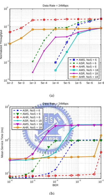
within a MPDU in ASR and ASR schemes. For AMS, the MSDU consists of 657 bytes information payload. (a) Normalized MAC Throughput, (b) Mean Service Time. . . 37
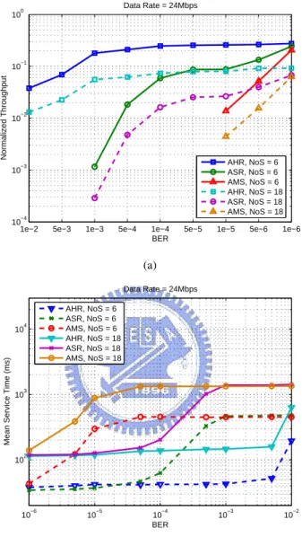
6.3 An aggregated frame consists of 50 MPDUs for AH-ARQ (AHR) and
ASR-ARQ(ASR). For pure aggregated MSDU mechanism (AMS), there are same number(50) of MSDUs within a MPDU. The information payload is 657- byte-long within a MPDU in ASR and ASR schemes. For AMS, the MSDU consists of 657 bytes information payload. (a) Normalized MAC Throughput, (b) Mean Service Time. . . 38
6.4 MAC Service Time Distribution of AH-ARQ under BER = 10-2; [α,β] = [5, 10], unsaturation case with five iterations. Number of RS blocks = 3, and each RS block consists of 219-byte-long information octets. . . 39 6.5 MAC Service Time Distribution of ASR-ARQ under BER = 2 x 10⁻⁴; [α,β] = [5,10], unsaturation case with five iterations. Each MPDU consists of 657-byte-long information payload. . . 39
6.6 Cumulated Density Function of ASR-ARQ Scheme under BER = 2 x 10⁻⁴, saturation case. NoS = 3, and each MPDU consists of 657-byte-long information payload. . . 40
6.7 Cumulated Density Function of ASR-ARQ Scheme under BER = 2.5 x 10⁻⁴, saturation case. NoS = 3, and each MPDU consists of 657-byte-long information payload. . . 40
6.8 Cumulated Density Function of AHR-ARQ Scheme under BER = 10-2, saturation case. NoS = 3, number of RS blocks = 3, and each RS block consists of
219-byte-long information octets. . . 41 6.9 Cumulated Density Function of AHR-ARQ Scheme under BER = 1.1 x 10⁻², saturation case. NoS = 3, number of RS blocks = 3, and each RS block consists of 219-byte-long information octets. . . 41
10.1 Left: the software and hardware architectures for the proposed ECMR protocol; Right: the snapshot of the PCM-7230 ARM-based embedded
platform . . . 55
10.2 The network topology for field experiments: the source node S communicates with three receivers R1, R2, and R3 via the intermediate nodes I1 and I2. The solid
lines denote the connectivity between the corresponding two nodes. . . 56 10.3 (a) Energy Consumption for Relaying Data Packets vs. Round Index, (b) Packet Delivery Ratio vs. Packet Inter-Departure Time. . . 58
Part I
Performance Analysis of MAC Defined
Hybrid ARQ Scheme for Next
Chapter 1
Introduction
In recent years, the techniques for wireless local area networks (WLANs) have been prevailing ex-ploited for both indoor and mobile communications. The applications for WLANs include point-to-point bridges and ad-hoc networking. Among different techniques, the IEEE 802.11 standard is the considered the well-adopted suite due to its remarkable success in both design and deployment.
Various amendments are contained in the IEEE 802.11 standard suite, mainly including IEEE 802.11a/b/g , IEEE 802.11e for quality-of-service (QoS) support, and the IEEE 802.11n [1] [2] [3] for high throughput performance. The simplicity of the carrier sense multiple access with collision avoidance (CSMA/CA) scheme for the medium access control (MAC) has contributed to the success of the IEEE 802.11 specifications. The WLAN devices that implement the IEEE 802.11b Physical (PHY) layer support the data transmission rate of 11 Mbps; while the data rate of the IEEE 802.11a PHY technique can sustain up to 54 Mbps with the adoption of the orthogonal frequency-division mul-tiplexing (OFDM) transmission scheme. Moreover, there are increasing demands for high throughput communication devices in order to support multimedia applications, e.g. HDTV and DVD. In order to fulfill the requirement for achieving improved throughput performance, the IEEE 802.11 task group N (TGn) enhances the PHY layer data rate to 600 Mbps by adopting advanced communication tech-niques, such as multi-input multi-output (MIMO) technology [4]. It is noted that MIMO technique utilizes spatial diversity to improve both the range and spatial multiplexing for achieving higher data rate. However, it has been investigated in [5] that simply improves the PHY data rate will not be
suf-fice for enhancing the system throughput from the MAC perspective. Accordingly, the IEEE 802.11 TGn further exploits frame aggregation and block acknowledgement techniques [6] to moderate the drawbacks that are originated form the MAC/PHY overheads.
Although the frame aggregation can reduce both the transmission time for frame headers and the contention time induced by the random back-off period, a larger aggregated frame will cause each station to wait for an elongated period before the next chance for channel access. Furthermore, under the error-prone channels, corrupting an aggregated frame can result in the wastage of a longer period of channel time and consequently lead to a lowered MAC throughput. As a result, a feasible design of the retransmission mechanisms becomes a significant topic with the existence of the frame aggregation scheme.
The automatic retransmission request (ARQ) [7] [8] [9] mechanisms have been extensively pro-posed in different wireless systems for reliable transmission. In order to reach more reliable transmis-sions within a shorter delivery period, the hybrid ARQ (H-ARQ) schemes [10] [11], which combine both the forward error correction (FEC) and the retransmission mechanism, have been proposed for advanced multimedia applications. In general, the H-ARQ mechanisms can be classified into three categories. In the type-I H-ARQ scheme [12], as a error packet is detected via the cyclic redundancy check, the transmitter will retransmit the same packet either until the packet is successfully decoded at the receiver or a maximum retransmission limit is reached. Type-II of H-ARQ scheme is regarded as the full incremental redundancy(IR) technique [13], which decreases the coding rate in each re-transmission by sending additional redundancy check digits. On the other hand, type-III of H-ARQ scheme [14], considered as a partial IR scheme, not only decrements the coding rate but also main-tains the self-decoding capability in each retransmission. It is noted that the IR-based schemes in general make use of the rate compatible punctured convolutional (RCPC) codes [14] [15] or the rate compatible punctured turbo (RCPT) codes. Moreover, the transmission errors are in general corrected in two phases based on the design concept of the concatenate code [16]. The inner decoder, which is implemented in the PHY layer, adopts sophisticated algorithms for error correction; while the outer decoder is served as the second stage fine-tuning error corrector that is operated in the MAC layer protocols. As a consequence, the FEC scheme in type-II and III of H-ARQ algorithms is regarded as
the inner decoder; while that of type-I scheme is considered as the outer decoder.
However, none of the existing ARQ algorithms are specifically designed under the scenarios with frame aggregation. It is require to provide an efficient retransmission scheme such as to enhance the system throughput for the IEEE 802.11n networks. In this paper, two ARQ schemes are proposed to consider the effect from frame aggregation in order to improve the network throughput. An aggre-gated selective repeat ARQ (ASR-ARQ) algorithm is proposed, which incorporate the selective repeat ARQ scheme with the consideration of frame aggregation. On the other hand, the aggregated hybrid ARQ (AH-ARQ) mechanism is proposed to further enhance the throughput performance for the IEEE 802.11n networks. It is considered as a Type-I of H-ARQ algorithm, which can be served as a outer code designed from the MAC layer perspective. The Reed-Solomon (RS) code [17] [18], which de-fines finite codeword length, is adopted within the proposed AH-ARQ scheme. Furthermore, it will be beneficial to construct effective analytical models to evaluate of the retransmission mechanisms for the IEEE 802.11n networks. There are existing studies propose analytical models for performance evalua-tion of the MAC channel access [19] [20] [21] and the frame aggregaevalua-tion techniques [22] [23] [24] for the IEEE 802.11-based networks. However, none of these models considers efficient retransmission schemes that are especially feasible for the high throughput required environments. As a result, the analytical models for both the ASR-ARQ and the AH-ARQ algorithms are established in this paper, where the scenarios with and without the collision probability are considered. Simulations are also conducted to validated and compare the proposed ARQ schemes based on the service time distribu-tion. It will be shown in the numerical evaluation that the AH-ARQ algorithm outperform the other schemes owing to its efficient utilization of the FEC mechanism.
The remainder of the first part is organized as follows. chapter 2 describes the conventional and newly defined MAC mechanism for 802.11n. The proposed analytical model for MAC mechanisms are in chapter 2, 3, and 4. Chapter 5 provides the performance evaluation and chapter 6 draws the conclusions.
Chapter 2
Proposed Automatic Retransmission
reQuest Mechanisms
2.1 Frame Aggregation/De-aggregation of IEEE 802.11n MAC Protocol
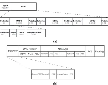
The IEEE 802.11n standard mandates the implementation of frame aggregation scheme for the sake of promoting the transmission efficiency. It is noted that the transmission efficiency is defined as the time for delivering the information payload over the time durations for transmitting the entire aggregated frame associated with the required control packets and the contention period. With frame aggregation scheme as shown in Fig. 2.1(a), multiple MAC protocol data units (MPDUs) are combined into an aggregated MPDU (A-MPDU), which is consequently transported into a single PHY service data unit (PSDU). Intuitively, the transmission efficiency can be improved with the utilization of the A-MPDU since more MPDUs are transmitted with a communion of control overhead.Each MPDU is padded with a MPDU delimiter for the purpose of extracting the corresponding MPDU from the aggregated frame. The extracting delimiter is composed of four bytes as shown in Fig. 2.1(a), including the reserved, MPDU length, CRC, and the unique pattern (UP) fields. It is noted that the UP field, which is set to the ASCII value of character ‘N’, is employed to detect a MPDU delimiter while scanning within the aggregation. Moreover, each MPDU is padded to become a multiple of 4 octets as shown in Fig. 2.1(a). The de-aggregation procedure at the receiver side that
PLCP Header PSDU Delimiter !!!5C MPDU 151:7C Padding !14C Delimiter !!!5C ! MPDU !151:7C Padding !14C Delimiter !!!5C MPDU 151:7C Padding !14C Reserved !5cjut Length !23cjut CRC-8 !9cjut Unique Pattern !!!!!9cjut (a)
Delimiter MAC Header
HDR FCS FECPayload-1 FCS FEC Payload-N FCS FEC
FCS Padding MSDU(s)
Reserved MPDU-Length FCS Unique-Pattern FEC
(b)
Figure 2.1: Frame aggregation: (a) A-MPDU frame format, (b) Modified MPDU format for AH-ARQ. was described in the standard is rewritten into pseudo-code as shown in Algorithm 1. The receiver verifies the validity of the MPDU delimiter via the valid MPDU Delimiter function (in Algorithm 1) based on the 8-bits CRC and the observation of the UP field, i.e. with character ‘N’. The MPDU will be successfully extracted from the aggregate if the MPDU delimiter is found to be valid. On other other hand, the de-aggregation process will move forward with four bytes (i.e. the offset parameter in Algorithm 1) and continue to verify if the next multiple of four octets contains a valid delimiter.
Algorithm 1: De-aggregation Process for an A-MPDU offset = 0 ;
while offset+4 ≤ A M P DU length do length = get M P DU length(of f set) ;
if [valid M P DU delimiter(of f set)] = T rue & [0 < length ≤ M ax M P DU length] = T rue then
Receive MPDU(offset+4,length) ;
of f set = of f set + 4 ∗ d(length + 4)/4e ; else
2.2 Proposed Aggregated Selective Repeat (ASR) ARQ Scheme
The design of retransmission mechanisms is consider and open topic from standpoint of the IEEE 802.11n standard. In this paper, the proposed ASR-ARQ scheme is modified from the conventional selective repeat (SR) ARQ mechanism to consider the packet aggregation within the design of retrans-mission mechanism. Contributing from the availability of the block acknowledgement (BA) scheme within the IEEE 802.11n standard, the ASR-ARQ algorithm can be effectively designed to provide transmission efficiency. Instead of sending each MPDU within an A-MPDU, the receiver replies with a BA frame for acknowledging the entire A-MPDU that is initiated from the transmitter. The BA frame consists of 32 octets which contains a bitmap field. Each bit in the bitmap field identifies whether the corresponding MPDU from the aggregated frame has been correctly received. As a consequence, the single BA frame reduces the control overhead comparing with conventional design by sending multiple ACK frames for an aggregated data frame.
In the proposed ASR-ARQ scheme, each MPDU is identified via a unique sequence number while an aggregated frame is transmitted. In the case that some of the MPDUs within an A-MPDU are miss-ing durmiss-ing the transmission, the ASR-ARQ algorithm will continue to retransmit those unsuccessfully transmitted MPDUs until all the MPDUs have either been positively acknowledged by the BA frame or reach the retry limitation. For instance, there are N MPDUs contained within an A-MPDU that are identified by the sequence numbers from 1 to N . If the MPDUs with sequence numbers 3 and 5 are corrupted and are identified via CRC check, the receiver will reply with the BA frame which denotes two zero flags at the corresponding third and fifth bits within the bitmap field. A new aggregated frame, which includes only the third and fifth MPDUs, will be delivered by the transmitter at the next transmission opportunity. The retransmission procedure terminates until either all the MPDUs with sequence numbers from 1 to N are correctly accepted by the receiver or the maximum number of retransmission trials (i.e. identified by the Retry Limit parameter) has achieved.
2.3 Proposed Aggregated Hybrid (AH) ARQ Scheme
In order to further enhance the transmission efficiency, the AH-ARQ scheme is proposed to integrate both the RS-based FEC and the retransmission mechanisms. Both the FEC and the retransmission schemes are described in the next two subsections.
2.3.1 FEC Mechanism of AH-ARQ Scheme
Based on the existing IEEE 802.11n MAC frame structure, the proposed FEC mechanism is con-structed according to the RS code that are well-adopted in the design of outer decoders. The
coeffi-cients of the generator polynomial G(x) are elements in a finite field GF (2m), where m = 8 is chosen
according to the byte-oriented system. For a (n, k, τ ) RS code, the set of roots α = {α, α2, ..., α2τ}
of G(x) are selected from the GF (28), where α is a primitive element of the finite field. As a result,
the generator polynomial G(x) can be represented as G(x) =Q2τk=1(x + αk) = x2τ +P2τ −1
i=0 gixi.
Based on the cyclic property of the RS code, the set of codewords can be formed with the multipli-cation of both the G(x) and the information symbols polynomial I(x). Moreover, the RS code will
have the minimum codeword distance dmin ≥ 2τ + 1 in the case that all the coefficients gi (for all
i ∈ {0, ..., 2τ − 1}) are not equal to zero. Therefore, the corresponding RS code possesses the
correct-ing capability of τ error symbols associated with the codeword length of 28− 1 = 255 octets and k
information octets. There are total of n − k = 2τ parity check octets, which are served as the
remain-der R(x) while dividing x2τI(x) by the generator polynomial G(x). In order to extract the newly
defined MPDU that includes the FEC mechanism, a modified de-aggregation procedure is performed as shown in Algorithm 2. At the beginning, the scanning process will start to search for the UP. After the UP has been identified, an additional predefined symbol will be traversed for verifying the usage of the FEC scheme. In other words, a valid delimiter will be identified if the recovered reserved field within the delimiter matches the ASCII value of character FF. It is noted that other functionalities can be referred as in Algorithm 1 in the similar manner.
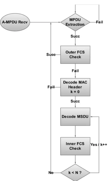
After the de-aggregation process has been defined, the entire mechanism for the MS to manage the incoming A-MPDU is explained as follows (as in Fig. 2.2). The MS will first start to extract each MPDU within an A-MPDU based on Algorithm 2. In the case that the MS has successfully
Algorithm 2: FEC-enhanced De-aggregation Process for an A-MPDU offset = 0 ;
while of f set + 4 + 2t ≤ A M P DU length do length = get MPDU length(offset) ;
if Succ Dec Delimiter(of f set, of f set + 4) then
if [valid f cs check(of f set)] = T rue & [get reserved bits(of f set) = F F ] = T rue & [length ≤ M ax M P DU length] = T rue then
RS Dec MPDU(offset+4+2t,length); offset = offset + 4 · d(4 + 2t + length)/4e ; end else offset = offset + 4; end end else
if [valid f cs check(of f set)] = T rue & [length ≤ M ax M P DU length] = T rue then
Normal Recv MPDU(offset+4,length) ; offset = offset + 4 · d(length + 4)/4e ; end else offset = offset + 4; end end end
Figure 2.2: Flow diagram for the MS to process the incoming A-MPDU, where N denotes the number of RS codewords within a MPDU.
extracts an MPDU and observing that the corresponding outer FCS is correct, the MS will enable the corresponding bits within the bitmap field of the BA frame. On the other hand, if the outer FCS of the corresponding MPDU is incorrect, the MS will execute the RS decoder in order to decode the RS block in the MAC header. It is noted that the well-adopted Berlekamp’s iterative algorithm is adopted to implement the decoding procedure. If either the decoding process fails or the invalid inner FCS of the MAC header RS block occurs, the process will be terminated with disabling the corresponding bits within bitmap field of BA frame. On the other hand, if the MS successfully decodes the MAC header RS block, it will continue to decode the entire MPDU via the RS decoder. The MS will set the corresponding bits within the bitmap field of the BA frame according to the above results. As a result, the MS will send a BA frame back to the AP if it has successfully extracted each MPDU from the A-MPDU.
2.3.2 Retransmission Mechanism of the AH-ARQ Scheme
The flow diagram for the retransmission mechanism of the proposed AH-ARQ scheme is depicted in Fig. 2.3. It is noted that the main concept of the retransmission scheme is to implement the conventional ASR-ARQ scheme on the codeword basis. The receiver will store the correctable RS block and combines these blocks with remaining retrieved correctable RS blocks in order to form a complete new frame. The detail mechanism is explained as follows. Initially, the transmitter starts by transmitting an A-MPDU with M MPDUs and M × N RS blocks to the receiver. After receiving the A-MPDU, the receiver will extract each MPDU with the adoption of Algorithm 2. The receiver finds errors within a set of RS blocks that are correctable, it will enable the corresponding bits within bitmap field of BA frame. On the other hand, if these RS blocks are uncorrectable, the receiver disables the corresponding bits of the MPDU within bitmap field of BA frame. The receiver will stores the set of correctly received RS blocks of the MPDU and the associated header information, i.e. both the sequence number and the retried times of this MPDU. The receiver will consequently send a BA frame back to the transmitter if all the MPDUs of an A-MPDU have been extracted. The transmitter retransmits an A-MPDU with each MPDU containing both the MAC header RS block and other uncorrectable RS blocks in ascending sequence.
Chapter 3
System Models
In this section, the required system models for the design of the proposed ARQ schemes are explained. Section 3.1 describes the queuing model for the 802.11n MAC protocol under the unsaturated situa-tion. The service models based on the Markovian chain are presented in Section 3.2.
3.1 Queuing Model of Frame Aggregation
In order to describe the traffic characteristics of the 802.11n MAC protocol for the unsaturated case, a discrete time M/G[α,β]/1/K queuing model is adopted in this paper. It is noted that [α, β] denotes the
integer range for the total number of aggregated packets, and K is the maximum number of packets
that can be stored in the queue. An imbedded Markov process ξnis considered at the time instant δn−
just before the departure of the aggregated packets. The discrete form of ξ(δ−
n) can be represented by
the state space S = {Sj| j ∈ N, 0 ≤ j ≤ K}, where Sjdenotes that there are j packets waiting in the
queue; while the transition probability can be defined as p(m)ij = P rob.{ξ(δ−
n) = Sj|ξ(δ−n−m) = Si}.
From the properties of ergodic Markov chains, the convergence of transition probability is obtained
as limm→∞p(m)ij = pij. The steady state probabilities are represented as πj = limm→∞πj(m) =
K → ∞), the steady state probabilities πj can be obtained as πj = k0 Pβ i=0πi, for j = 0 Pβ i=0kj· πi+ Pβ+j
i=β+1kβ+j−i· πi, for j ≥ 1
(3.1)
where kj =
R∞
0 e−λt (λt)
j
j! dT (t). T (t) represents the cumulative distribution function (CDF) of
service time distribution for medium access delay, and λ indicates the packet arrival rate. On the other
hand, considering the case with limited queue length K, the steady state probabilities πj as in (3.1)
can be modified as πj = k0 Pβ i=0πi, j = 0 Pβ i=0kj· πi+ Pβ+j i=β+1kβ+j−i· πi, 1 ≤ j < K − β Pβ i=0kj· πi+ PK i=β+1kβ+j−i· πi, K − β ≤ j < K 1 −PK−1i=0 πi, j = K 0, j > K (3.2)
It is noted that the queuing model with limited queue length (as in (3.2)) will be utilized in chapter 5 for the derivation of unsaturated performance of the proposed ARQ schemes.
3.2 Service Models
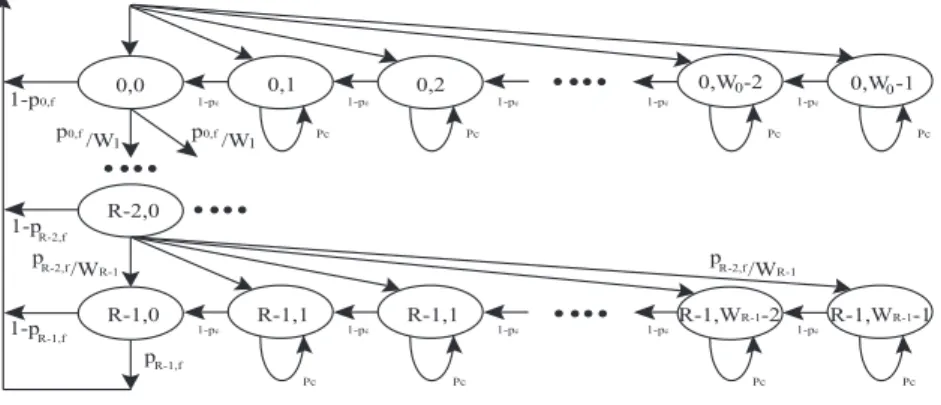
As shown in Fig. 3.1, the state probability bi,j for the AP can be derived from the Markov-Chain
model. It is noted that bi,0 = pi−1,f · bi−1,0, where bi,j denotes the state probability identified by the
(i, j) pair and pi−1,f represents the failed transmission probability at the (i−1)th stage. It is noted that
pi−1,f will be acquired in the latter subsections based on the different proposed schemes. Therefore,
the state probability bi,jcan be inferred as
bi,j = 2iW −1 X k=j bi−1,0· pi−1,f 2iW = (1 − j 2iW)bi−1,0· pi−1,f (3.3)
0,1 0,0 0,2 0,W -20 0,W -10 p0,f /W1 p0,f /W1 1-p0,f 1-pR-2,f 1-pR-1,f pR-2,f /WR-1 pR-1,f pR-2,f /WR-1 Pc Pc Pc Pc R-2,0 R-1,0 R-1,1 R-1,1 R-1,WR-1-2 Pc Pc Pc Pc R-1,WR-1-1 1-pc 1-pc 1-pc 1-pc 1-pc 1-pc 1-pc 1-pc 1-pc 1-pc
Figure 3.1: Markov chain for service time models.
where W indicates the minimum contention window size. Based on (3.3) and bi,0=
Qi−1
j=0pj,f · b0,0,
the probability that the MAC service is busy can be obtained as
Pbusy = R−1X i=0 2iW −1 X j=0 bi,j = R−1X i=0 b0,0(2 |i+M |−|i−M | 2 W + 1) 2 i−1 Y k=0 pk,f (3.4)
where R indicates the retry limit and M denotes the maximum number of retransmissions. Therefore,
the maximum contention window size becomes 2MW . Consequently, the transmitting probability τ
condition on that the MAC is busy becomes
τ = PR−1 i=0 bi,0 Pbusy = 1 +PR−1i=1 Qi−1k=0pk,f W +1 2 + PR−1 i=1 (2 |i+M |−|i−M | 2 W +1) 2 Qi−1 k=0pk,f (3.5)
On the other hand, the service model with collision probability pcnot equals zero is considered
the state probability bi,jfor the case that pc6= 0 can be inferred as bi,j = bi−1,0· pi−1,f, j = 0 pi−1,f · (1 −2ijW) · bi−1,0 1−pc, 1 ≤ j < 2 iW − 1 (3.6)
for 1 ≤ i < R. Based on (3.6) and bi,0 = b0,0Qi−1m=0pm,f, the transmitting probability τ , collision probability pc, and successful transmission probability pscan be obtained as
τ = 1 + PR−1 i=1 Qi−1 m=0pm,f 1 +2(1−pW −1c)+PR−1i=1 [1 +2 |M +i|−|M −i| 2 W −1 2(1−pc) ] Qi−1 m=0pm,f (3.7) pc= 1 − (1 − τ )N −1 (3.8) ps= (N − 1)τ (1 − τ )N −2 (3.9)
Chapter 4
Unsaturated Performance Analysis of
Proposed ARQ Schemes
In this chapter, the performance modeling of the proposed ASR-ARQ and AH-ARQ mechanisms are established under the unsaturated situation; while limited queue with queue length is equal to K is considered. A pair of transmitter and receiver with either up-link or down-link unicast transmission is considered for performance analysis. Furthermore, the distributed coordination function (DCF) is employed as the medium access scheme for one access category between the transmitter and the receiver. The request-to-send/clear-to-send (RTS/CTS) mechanism is used for channel reservation for enhancing basic access mechanism. The packet size of the incoming MAC service data units (MSDUs) are assumed fixed. The performance analysis for both the proposed ASR-ARQ and AH-ARQ schemes are explained in Sections 4.1 and 4.2. The iterative algorithm for conducting the ARQ schemes are presented in Section 4.3.
4.1 Modeling of Service Time Distribution of Proposed ASR-ARQ Scheme
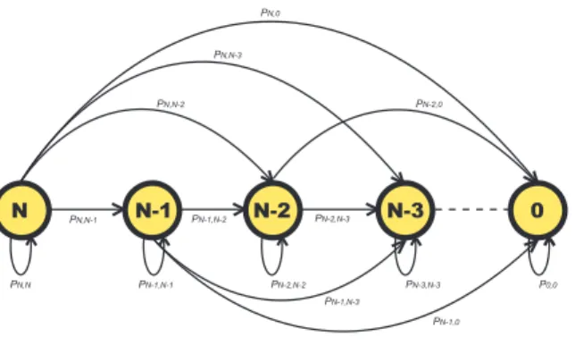
The service time distribution for the transmitter can be obtained from the state diagram based on the modified Bianchi’s model [19]. As stated in the IEEE 802.11n standard, the time duration for longPN,N-1 PN-1,N-2 PN-2,N-3 PN-1,N-3 PN-1,0 PN,N-2 PN,N-3 PN,0 PN-2,0 PN,N PN-1,N-1 PN-2,N-2 PN-3,N-3 P0,0 N N-1 N-2 N-3 0
Figure 4.1: Signal flow graph of the specified Markov chain with initial state N.
transmission, i.e. TLN AV = TRT S+ TCT S+ 2TA−M P DU+ 2TBA+ 5TSIF S. The second A-MPDU
time duration is occupied only if the first A-MPDU is failed in transmission. In order to calculate the probability mass function of random variable which denotes the required times such that all the MPDUs have been positive acknowledged based on the proposed ASR-ARQ scheme, the signal flow
graph of the specified Markov chain is depicted as in Fig. 4.1. The recurrent relationship Fj(D) can
be formulated as Fj(D) = 1, for j = 1 Pj k=0 Pk
m=0CkjCmk(1 − pf,e)j−mpk+mf,e DFm(D), for j > 1
(4.1)
where D represents the transition gain as the state changes, and pf,e denotes the frame error
proba-bility. In order to solve the recurrent equation as in (4.1), the transformed function ˜F (x) is defined as ˜ F (x) , ∞ X j=0 Fj(D)x j j!. (4.2)
By substituting x in (4.2) with p2f,ex associated with the relationships e(1−pf,e)x =P∞
j=0 [(1−pf,e)x]j j! and e(1−p2f,e)x=P∞ j=0 [(1−p2 f,e)x]j j! , ˜F (x) can be acquired as ˜
By defining Q(x) , F (x)˜ex , (4.3) can be rewritten as
Q(x) = Q(p2f,ex)D + (1 − D)e−x (4.4)
On the other hand, Q(x) can be written as
Q(x) = ∞ X j=0 Qj(D)xj j! (4.5)
By incorporating (4.4) and (4.5), Q(x) can be obtained as
Q(x) = ∞ X j=0 [D(p 2 f,ex)j j! Qj(D) + (−1) j(1 − D)xj j!] . (4.6)
which can further be rewritten as
Qj(D) = (−1)
j(1 − D)
1 − Dp2jf,e . (4.7)
By substituting (4.7) into (4.5), ˜F (x) can be rewritten as
˜ F (x) = exQ(x) = X∞ j=0 (−1)j(1 − D) 1 − Dp2jf,e xj j! ·X∞ k=0 xk k! . (4.8)
Finally, Fj(D) can be obtained from (4.2) and (4.8) as
Fj(D) = j X k=0 j! (j − k)!k! (−1)k(1 − D) 1 − Dp2k f,e . (4.9)
The recurrent function Fj(D) as in (4.9) implies the mechanism of the SR-ARQ scheme, which will
also later be utilized for the computation of the failed transmission probability pm,f.
Moreover, it is noticed that the medium access delay can be divided into two parts, including the back-off delay and the transmission delay. First of all, the back-off delay is represented by considering
delay at the ith back-off stage Hi(z) is obtained as Hi(z) = 1 2iW P2iW −1 k=0 Hdk(z), 0 ≤ i < M 1 2MW P2MW −1 k=0 Hdk(z), M ≤ i ≤ R − 1 (4.10)
On the other hand, the transmission delay is composed by both the unsuccessful and the
success-ful transmission time. The conditional PGF Em,fj (z) by considering the unsuccessful transmission
between the mth and the (m + 1)th back-off stages can be written as
Em,fj (z) = β X j=α pj 1 − pjm,0 j X k=1 pjm,k ps,k k X i=1
Cikpif,e(1 − pf,e)k−izTRT S+TCT S+3TSIF S+kη+TBA i
X
l=1
Cliplf,e(1 − pf,e)i−lziη+2TSIF S+TBA (4.11)
where ps,k = 1 −
Pk
v=0Cvkpvf,e(1 − pf,e)k. It is noted that Ejm,f(z) corresponds to the PGF of the
failed transmission time at the mth stage, where j denotes that there are j MPDUs initially aggregated.
The parameter η in (4.11) is acquired as η = (Nd× Ts)/B(m), where Ndrepresents the number of
data bytes per MPDU, Tscorresponds to the symbol duration, and B(m) indicates the number of data
bytes per OFDM symbol in the transmission mode m with one spatial stream. The distribution of
aggregated pj can be obtained as
pj = Pα i=0πi, j = α πj, α < j < β PK i=βπi, j = β (4.12)
where πjs are obtained from (3.2) in chapter IV under the case of limited queue length. The
param-eter pjm,k denotes the probability that there are k unsuccessfully transmitted MPDUs, which can be
represented as the (k + 1)th element of the vector vp(m), i.e. pjm,k = [vp(m)]1,k+1. It is noticed that
vp(m)= v(0)p ×P2m, which corresponds to the multiplication of the initial vector v(0)p = [0 0 ... 0 1] and
as pi,j = 1, i = j = 0
Cjipjf,e(1 − pf,e)i−j, i ≥ j
0, i < j
(4.13)
Furthermore, the probability pjm,0within (4.11) can be obtained from the recursion equation (4.9) as
pjm,0 = m X k=1 dkF j(D) k!dDk (4.14)
Moreover, the conditional PGF Snj(z) of the j initially aggregated packets in service for the successful
transmission time at the n-th back-off stage is obtained as
Snj(z) = β X j=α pj 1 − pjn,0 j X k=1 pjn,k p²,k[(1 − pf,e) kzTRT S+TCT S+3TSIF S+kη+TBA + k X i=1
Cikpif,e(1 − pf,e)kzTRT S+TCT S+5TSIF S+(k+i)η+2TBA] (4.15)
where p²,k = 1 −Pkl=1Plr=1Ck
lCrlpl+rf,e(1 − pf,e)k−r. As a consequence, the overall PGF T (z) of
the MAC access time distribution can be formulated by combining (4.10), (4.11), and (4.15) as
T (z) =(1 − p0,f)zTDIF SH0(z)S0(z) + { R−1X i=1 {[ i Y j=0 zTDIF SH j(z)][ i−1 Y m=0 pm,fEm,f(z)]} (1 − pi,f)Si(z)} + R−1Y i=0 zTDIF SH i(z) R−1Y m=0 pm,fEm,f(z) (4.16)
where the failed transmission probability pm,f at m-th stage could be calculated as
pm,f =Pβj=αpj
Pj
4.2 Modeling of Service Time Distribution of Proposed AH-ARQ Scheme
In this section, the performance analysis and modeling of the service time distribution of the proposed AH-ARQ scheme is presented. Based on the RS code, it is assumed that the decoding errors will occur while there are more than t corrupted symbols within a predefined block. Therefore, a decoding error probability Pblock,eof a block can be formulated asPblock,e =
n
X
i=t+1
Cknpks,e(1 − ps,e)n−k (4.17)
where n = 2m− 1 represents the codeword length. It is noted that p
s,e represents the error rate of an
RS symbol defined in GF (2m) with m bits, i.e. p
s,e = 1 − (1 − pb,e)mwhere pb,ecorresponds to the
bit error rate. As a result, the recurrent relationship defined for transmitting A-MPDUs in one LNAV channel reservation duration could be reformulated as
Fi(D) = 1, i = 0 P2 eDFi(D) + 2Pe(1 − Pe)D Pi
k=0CkiPblock,ek (1 − Pblock,e)i−kFk(D)+
(1 − Pe)2D
Pi
k=0
Pk
l=0CkiClkPblock,ek+l (1 − Pblock,e)i−lFl(D), 1 ≤ i ≤ N
(4.18)
where N denotes the number of codewords in an MPDU and Pe represents the union of the error
probabilities from both the packet header and the delimiter, i.e. Pe= phdr,e∪ pdelimiter,e = phdr,e+
pdelimiter,e− phdr,e· pdelimiter,e. It is noticed that if the value of Peis greater than 0, the entire MPDU
will be retransmitted. In order to represent the case for a MPDU that is composed of N RS blocks under error-prone channels, similar procedures as in (4.2) - (4.9) are adopted for solving the recurrent
relationship. The recurrent function Fi(D) can be acquired as
Fi(D) = i X k=0 i! (i − k)!k! (D − 1)(−1)k 2DPe(1 − Pe)Pblock,ek + D(1 − Pe)2Pblock,e2k − (1 − DPe2) (4.19)
for 1 ≤ i ≤ N . Consequently, an MPDU consists of N RS blocks with retransmission mechanism un-der error-prone channel is depicted. It is noted that the recurrent function Fi(D) obtained from (4.19)
is considered as follows. A discrete random variable X is considered which indicates the number of retried transmissions until all the RS blocks of an A-MPDU have been positive acknowledged. The probability density function (PDF) of X can be represented as
PX(x) = " x X i=1 1 i! diFN(D) dDi #j u(x) − "x−1 X i=1 1 i! diFN(D) dDi #j u(x − 1) (4.20)
In order to calculate the service time distribution of the proposed AH-ARQ scheme, both the PGFs for the failed transmission Em,fj (z) and successful transmission Sm,fj (z) are to be acquired. The transfer function of the failed transmission time Em,fj (z) at mth back-off stage is formulated as
Em,fj (z) ' N X k=1 pN m,k (1 − pN m,0)p(F EC)s,k [Pe2z2toh+2kη+2TBA+3TSIF Sj + (1 − Pe)Pe k X i=1
CikPblock,ei (1 − Pblock,e)k−iz2toh+(k+i)η+
2TBA+3TSIF S j + (1 − Pe)Pe k X i=1
CikPblock,ei (1 − Pblock,e)k−iz2toh+2kη+2TBA+3TSIF Sj +
(1 − Pe)2 k X i=1 i X l=1
CikCli(1 − Pblock,e)k−lPblock,ei+l z2toh+(k+i)η+
2TBA+3TSIF S
j ]zTRT S+TCT S+2TSIF Sj
(4.21) where p(F EC)s,k = 1−(1−Pe)(1−Pblock,e)k−Pe(1−Pe)(1−Pblock,e)k−(1−Pe)2
Pk
i=1CikPblock,ei (1−
Pblock,e)k. It is noted that the approximation is resulted from the case that the communion of time
intervals for control packets. kη represents the time interval for each RS block transmission; while
tohcorresponds to the time for k codewords to share one MAC header. The parameter pjm,krepresents
the probability that there are k unsuccessfully received RS blocks after m retransmissions, which can be represented as the (k + 1)th element of the vector vp(m), i.e. pjm,k = [v(m)p ]1,k+1. It is noticed that
vp(m) = v(0)p × T2m, which corresponds to the multiplication of the initial vector v(0)p = [0 0 ... 0 1]
within T(N +1)×(N +1)can be acquired as ti,j = 1, i = j = 0 Pe+ (1 − Pe)Pblock,ei , 1 ≤ i ≤ N, j = i
Cji(1 − Pe)Pblock,ej (1 − Pblock,e)i−j, 0 ≤ j < i
0, i < j
(4.22)
And from eqn. (4.20),
PX(x) = (pNx,0)ju(x) − (pNx−1,0)ju(x − 1). (4.23)
Consequently, pN
m,0 can be derived. Furthermore, the successful transmission time between stage m
and stage m + 1 is depicted as
Smj (z) ' N X k=1 pN m,k (1 − pN m,0)p(F EC)²,k [(1 − Pe)(1 − Pblock,e)kztoh+kη+ TSIF S+TBA j + Pe(1 − Pe)(1 − Pblock,e)kz2toh+2kη+ 3TSIF S+2TBA j + (1 − Pe)2 k X l=1
ClkPblock,el (1 − Pblock,e)kz2toh+(k+l)η+3TSIF S+2TBAj ]zTRT S+TCT S+2TSIF Sj (4.24) where p(F EC)²,k = 1−P2
e−2(1−Pe)Pe
Pk
i=1CikPblock,ei (1−Pblock,e)k−i−(1−Pe)2
Pk
i=1
Pi
l=1CikCli
Pblock,ei+l (1 − Pblock,e)k−l. Therefore, the PGF of the service time distribution for a single MPDU can
be obtained as T (z) '(1 − p0,f)zTDIF SH 0(zj −1 )S0j(z) + R−1X i=1 (1 − pi,f) (4.25) [( i Y l=0 zTDIF SH l(zj −1 ))( i−1 Y m=0 p(F EC)m,f Em,fj (z))]Sij(z) + R−1Y i=0 zTDIF SH i(zj −1 ) R−1Y m=0 pm,fEm,fj (z). (4.26)
where p(F EC)m,f represents the failed transmission probability for an MPDU containing N RS blocks,
i.e. pm,f =
PN
aggregated MPDUs can be obtained as Tov(z) = β X j=α pj· [T (z)]j (4.27)
where pj is acquired from (4.12).
4.3 Iteration Algorithm for Proposed ARQ Schemes
In order to calculate the service time distributions (i.e. (4.16) and (4.27)) for both the proposed ASR-ARQ and AH-ASR-ARQ schemes, an iteration algorithm is required to be exploited. The procedures of the iterative algorithm is listed as follows:
1. The algorithm starts with the saturation case with [pα...pβ] = [00...01] and [π0...πK] = [00...01]. 2. Calculate the PDFs of the MAC service time for either the ASR-ARQ scheme (i.e. (4.16)) or
the AH-ASR scheme (i.e. (4.27)).
3. Compute the transition probability kj '
P∞
i=0tie−λi (λi)
j
j! . It is noted that 1 µs is taken as the
time unit and ti denotes the probability that the service time is i µs. Consequently, the newly
updated [π0...πK] could be calculated.
4. The PDF of the MAC service time is recalculated via either (4.16) or (4.27). Compare the PDF with the previous computed value from step 2. If the value converges, the process stops here. Otherwise, the process goes to step 3.
Chapter 5
Performance Analysis of Proposed ARQ
Schemes with Existence of Interfering
Stations
In this chapter, the service time distribution for both the proposed ARQ schemes are acquired by considering the existence of interfering stations in the network. The centralized network topology is considered, where there are one access point (AP) and N stations. The N stations are contending for accessing the channel in order to communicate with the AP for data transmission. For simplicity, saturated queuing model is considered in this section, i.e. each station consistently has frames to be delivered. Section 5.1 described the modeling of service time distribution for the proposed ASR-ARQ scheme; while that of the AH-ARQ algorithm is presented in Section 5.2, where the existence of collision probability is considered in both cases.
5.1 Modeling of Service Time Distribution of Proposed ASR-ARQ Scheme
with Contending Stations
In this section, the service time distribution for the ASR-ARQ scheme is the existence of contending stations is derived. Three components are required to be obtained for the derivation of the service
time distribution Ttotal(z), i.e. the conditional PGF of consecutive back-off time slot Hd(z), the
con-ditional PGF Em,f(z) caused by failed retransmissions, the and conditional PGF Sn(z) of successful
transmission time. First of all, the conditional PGF of consecutive back-off time slot Hd(z) is derived via Mason’s gain rule [25] as
Hd(z) = (1 − pc)zσ
1 − (pc− ps)C(z) − psM (z)
. (5.1)
where (pc−ps)C(z)+psM (z) and (1−pc)zσcorresponds to the loop gain and the open loop gain
re-spectively. The collision probability pcand the successful transmission probability pscan be obtained
as from (3.8) and (3.9) via the Markov chain model. It is noted that C(z) = zTRT S+TSIF S+TCT S+TDIF S, and the conditional PGF M (z) of transmission time interrupted via another station is acquired as
M (z) = R−1X m=0 bm,0 τ (1 − pjm,0) j X k=1
pjm,k{(1 − pf,e)kzTRT S+TCT S+3TSIF S+kη+TBA+TDIF S+ k X l=1 l X n=0
ClkCnlpl+nf,e (1 − pf,e)k−nzTRT S+TCT S+5TSIF S+2TBA+(k+l)η+TDIF S} (5.2)
where the probability pjm,k in (5.2) is acquired as pjm,k = [v(m)1×(j+1)]k+1. The vector v(m)1×(j+1) is
obtained via v(m)1×(j+1) = v(0)1×(j+1)× Tm with initial probability vector v(0)
1×(j+1) = [0 0 ... 0 1]. The
elements within the transition matrix T(j+1)×(j+1)is obtained as
pi,j = 1, i = j = 0 pc+ (1 − pc)p2if,e, 1 ≤ i ≤ j, j = i (1 − pc) Pi−j
k=0CkiCi−j−ki−k (1 − pf,e)i−jpi+j−kf,e , 0 ≤ j < i
0, j > i
I1){* I2){* IS.3){* IS.2){* T1){* T2){* TS.3){* TS.2){* D){* D){* D){* D){* F1){* F2){* FS.3){* FS.2){* !!!2 Qd Qd Qd Qd Q1-g Q2-g QS.3-g QS.2-g 2.Q1-g 2.Q2-g 2.QS.3-g 2.QS.2-g
Figure 5.1: Service System Diagram.
Moreover, the conditional PGF Em,f(z) resulted from the error retransmissions between the mth and
the (m + 1)th back-off stages is computed as
Em,f(z) = j X k=1 pjm,k (1 − pjm,0)ps,k k X i=1 i X l=1
CikClipl+if,e(1 − pf,e)k−lzTRT S+TCT S+5TSIF S+2TBA+(k+i)η+TDIF S
(5.4)
where ps,k= 1 −
Pk
v=0Cvkpvf,e(1 − pf,e)k. The defined probability pjm,0can be also acquired as
pjm,0 = m X k=1 dkFj(D) k!dDk (5.5) where Fj(D) = j X k=0 j! (j − k)!k! (−1)k(1 − D) 1 − pcD − (1 − pc)Dp2k f,e (5.6)
It is noticed that the recurrent function Fj(D) in this case is considered for the mechanism of
selective-repeat retransmission, where the collision probability pcis included. Furthermore, the
depicted as Sn(z) = j X k=1 pjn,k (1 − pjn,0)p²,k
{(1 − pf,e)kzTRT S+TCT S+3TSIF S+kη+TBA+TDIF S+ k
X
i=1
Cikpif,e(1 − pf,e)kzTRT S+TCT S+5TSIF S+2TBA+TDIF S+(k+i)η} (5.7)
where p²,k = 1 −Pki=1Pil=1Ck
iClipl+if,e(1 − pf,e)k−l. As a result, the PGF of total service time
distribution Ttotal(z) referred as Fig. (5.1) is obtained as
Ttotal(z) =(1 − p0,f)H0(z)S0(z) + R−1X i=1 [ i Y k=0 Hk(z)][ i−1 Y l=0 (pcC(z) + (pl,f− pc)El,f(z))] (1 − pi,f)Si(z) + R−1Y i=0 Hi(z) R−1Y m=0 (pcC(z) + (pm,f− pc)Em,f(z)) (5.8)
where the failed transmission probability pm,f at the mth stage is acquired as
pm,f = pc+ (1 − pc) j
X
k=1
pjm,kps,k. (5.9)
5.2 Modeling of Service Time Distribution of Proposed AH-ARQ Scheme
with Contending Stations
In this subsection, the service time distribution for the proposed AH-ARQ scheme with the consider-ation of channel contention is addressed.
With the collision probability considered for the aggregated MPDUs, the PMF of the random variable X that represents the number of retransmissions until all MPDUs have been positively ac-knowledged is denoted as PX(x) = x X k=0 Ckxpkc(1 − pc)x−k· " ( x−k X i=1 diF N(D) i!dDi ) ju(x − k) − (x−k−1X i=1 diF N(D) i!dDi ) ju(x − k − 1) # (5.10)
where u(x) = 1 if x > 0 and u(x) = 0 for x ≤ 0. It is noticed that recursion function FN(D) can be obtained from (4.19), which addresses the retransmission mechanism on the RS-block basis. Similarly,
the conditional PGF Em,f(z) for unsuccessful transmissions between the mth and the (m+1)th stages
is modified for addressing the AH-ARQ scheme as
Em,f(z) = m X v=0 Cvmp v c(1 − pc)m−v 1 − (pN m−v,0)j j−1 X x=0 Cxj (p N m−v,0)x(1 − pNm−v,0)j−x 1 − [PNk=1 pNm−v,k 1−pN m−v,0(1 − p (F EC) s,k )]j−x j−x−1X i=0
Cij−x[A(m, v, z)iB(m, v, z)j−x−i· zTRT S+TCT S+5TSIF S+2TBA+TDIF S] (5.11)
where A(m, v, z) = N X k=1 pN m−v,k 1 − pN m−v,k [(1 − Pe)(1 − Pblock,e)kztoh+kη+ Pe(1 − Pe)(1 − Pblock,e)kz2toh+2kη + (1 − Pe)2 k X l=1 ClkPblock,el (1 − Pblock,e)kz2toh+(k+l)η] (5.12) B(m, v, z) = N X k=1 pN m−v,k 1 − pN m−v,0 [Pe2z2toh+2kη+ (1 − P e)Pe k X i=1
CikPblock,ei (1 − Pblock,e)k−iz2toh+(k+i)η
+ (1 − Pe)Pe k
X
i=1
CikPblock,ei (1 − Pblock,e)k−iz2toh+2kη
+ (1 − Pe)2 k X i=1 i X l=1
CikCli(1 − Pblock,e)k−lPblock,ei+l z2toh+(k+i)η]. (5.13)
Note that pN
m−v,k, k > 0 is defined in section 5.2, and from x
X
k=0
Ckxpkc(1 − pc)x−k[(px−k,0N )ju(x − k) − (pNx−k−1,0)ju(x − k − 1)] = PX(x), (5.14)
pNm−v,0could also be derived. It is noted that the 1−(pNm−v,0)jwithin (5.11) represents the normalized term, which corresponds to the probability that not all MPDUs have been successfully transmitted before the mth stage. The normalization probability 1 − [PNk=1 pNm−v,k
1−pN m−v,0
(1 − p(F EC)s,k )]j−xrepresents
the probability which excludes the case that all (j − x) MPDUs have been successfully delivered at the mth stage. It is noted that p(F EC)s,k is obtainable from chapter 5. Moreover, the conditional PGF
Sm(z) for the successful transmission time between the mth and (m + 1)th stages is acquired as Sm(z) = m X v=0 Cvmp v c(1 − pc)m−v 1 − (pN m−v,0)j j X x=1 Cxj(1 − p N m−v,0)x(pNm−v,0)j−x [PNk=1 pNm−v,k 1−pN m−v,0p (F EC) ²,k ]x [zTRT S+3TSIF S+TCT S+TBA+TDIF S ˜ B(m, v, z)x+ zTRT S+TCT S+5TSIF S+2TBA+TDIF S x X i=1 CixA(m, v, z)˜ iB(m, v, z)˜ x−i] (5.15) where ˜ A(m, v, z) = N X k=1 pN m−v,k 1 − pN m−v,0 [Pe(1 − Pe)(1 − Pblock,e)kz2toh+2kη + (1 − Pe)2 k X l=1 ClkPblock,el (1 − Pblock,e)kz2toh+(k+l)η] (5.16) ˜ B(m, v, z) = N X k=1 pN m−v,k 1 − pN m−v,0 [(1 − Pe)(1 − Pblock,e)kztoh+kη] (5.17)
It is noted that that the normalization term [PNk=1 pNm−v,k
1−pN m−v,0p
(F EC)
²,k ]x denotes the probability that
all the remaining MPDUs have been successfully retransmitted at the mth stage. ˜A(m, v, z) and
˜
B(m, v, z) represent the transfer function of transmitting time that take one or two transmission
op-portunities respectively. Furthermore, the conditional PGF of consecutive backoff time slot Hd(z) can
be obtained from (5.1), where the conditional PGF S(z) for of transmission time that is interrupted by another station is acquired as
M (z) = R−1X i=0 bi,0 τ i X x=0 Cxipxc(1 − pc)i−x 1 − (pN i−x,0)j j X v=1 Cvj(1 − pNi−x,0)v(pNi−x,0)j−v
[zTRT S+TCT S+3TSIF S+TBAB(i, x, z)˜ v+ zTRT S+TCT S+5TSIF S+2TBA+TDIF S
v X l=1 ClvA(i, x, z)˜ lB(i, x, z)˜ v−l + zTRT S+TCT S+5TSIF S+2TBA+TDIF S v X r=1 CrvB(i, x, z)rA(i, x, z)v−r] (5.18)
As a result, the PGF of total service time distribution Ttotal(z) is obtained as Ttotal(z) =(1 − p0,f)H0(z)S0(z) + R−1X i=1 [ i Y k=0 Hk(z)][ i−1 Y l=0 (pcC(z) + (pl,f− pc)El,f(z))] (1 − pi,f)Si(z) + R−1Y i=0 Hi(z) R−1Y m=0 (pcC(z) + (pm,f− pc)Em,f(z)) (5.19) where pm,f =pc+ (1 − pc) m X v=0 Cvmpvc(1 − pc)m−v j X i=1 Cij(1 − pNm−v,0)i(pNm−v,0)j−i i X l=1 Cil[( N X k=1 pN m−v,k 1 − pN m−v,0 p(F EC)s,k )l( N X k=1 pN m−v,k 1 − pN m−v,0 p(F EC)²,k )i−l] (5.20)
It is noted that the failed transmission probability Em,f(z) at the mth stage is obtained from (5.7).1
1The above equation (5.11) - (5.20) might suffer the case 00when m = v, k = 0, pN
m−v,k= 0. Here we treated the 00 equaling one.
Chapter 6
Performance Evaluation
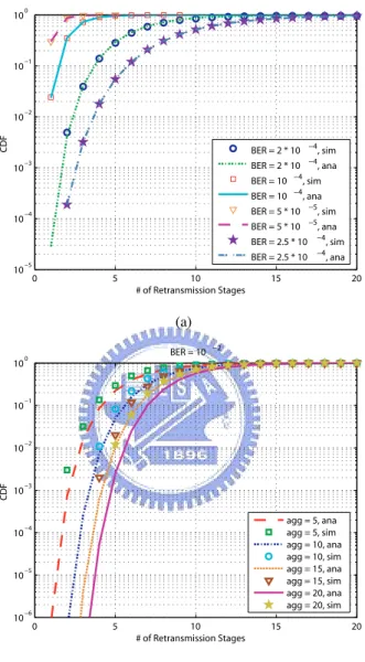
In this section, the numerical and simulation results are computed and verified for error prone chan-nels. The systemC/C++ simulation models are constructed based on the parameters listed in Table 6. It was considered a one hop network in the following discussions. The channel considered following regards PHY as a binary symmetric channel (BSC) and we omit the effects of PCLP protocols (i.e. synchronization errors, Tx period). First, we validate the analysis model of required retransmissions of both retransmission mechanisms under different BERs or aggregation numbers with existing of only one reverse/forward link. Fig. (6.1(a)) shows the distribution that the number of required retrans-mission times until all aggregated MPDUs have been positive acknowledged through the conventional ASR-ARQ. The number of aggregated MPDUs is fixed 10 with each MPDU size configured 1024 bytes and it has been validated at four different BERs. It could be observed that as the increment of number of retransmissions, the improvement of frame error rate becomes bigger at higher BERs. Fig. (6.1(b)) shows the cumulated density function of necessary retransmissions through AH-ARQ
scheme instead. The (255,223,16) RS code for AH-ARQ over GF (28) constructed via the primitive
polynomial 1 + x2+ x3+ x4+ x8is defined. Each 835-byte-long packet within A-MPDU consists of
three RS blocks which excludes the header and delimiter blocks. The differences among simulation
and analysis results could be explained from the upper bounded decoding error probability Pblock,e
as defined in equation 4.17. We have concluded while it is with more aggregated packets, the ad-vantages of boosting the retried times is more significant. Following we show the MAC service time

![Figure 6.4: MAC Service Time Distribution of AH-ARQ under BER = 10 −2 , [α, β] = [5, 10], unsaturation case with five iterations](https://thumb-ap.123doks.com/thumbv2/9libinfo/8740303.204099/53.892.298.617.201.451/figure-mac-service-time-distribution-arq-unsaturation-iterations.webp)
