Numerical investigation of the effect
of a transducer pulse on the microfluidic
control of a piezoelectric printhead
Jr-Ming Lai Jenn-Der Lin
National Chiao Tung University Department of Mechanical Engineering 1001 Ta Hsueh Road
Hsinchu 30050, Taiwan E-mail: jdlin@cc.nctu.edu.tw
Kung Linliu
National Synchrotron Radiation Research Center Scientific Research/Facility Utilization
101 Hsin-Ann Road Hsinchu Science Park Hsinchu 30076, Taiwan
Abstract. Numerical calculations are performed to investigate the effect of the component of a single transducer pulse on the ejection of a drop for a drop-on-demand ink-jet printhead with a piezoelectric actuator. The flow field is governed by continuity and Navier-Stokes equations. A volume-of-fluid method with a piecewise-linear interface construction is used to track the complicated topological variation of the liquid-gas inter-face. The computer code is validated with experimental results present in the literature. The volume of the primary drop is closely related to the maximum displacement Dfof chamber wall induced by the piezoelectric actuator in the forward stoke; the velocity of the primary drop depends on the ratio of Dfto the time period of the forward stoke⌬f. Moreover, the fact that the formation of the primary drop depends weakly on the con-ditions of the backward stroke is considered. A decreased interval be-tween forward and backward strokes might serve to suppress the forma-tion of satellite drops owing to reducing the liquid thread length lb at pinching off to a value less than the upper limit lb*. The breaking up of the freely flying liquid thread from nozzle outlet has two modes—multiple breaking up and end pinching—and depends on the thread length at pinching off. © 2010 Society of Photo-Optical Instrumentation Engineers.
关DOI: 10.1117/1.3486201兴
Subject terms: piezoelectric inkjet printhead; drop-on-demand; drop ejection; microfluidic; transducer pulse; satellite drops.
Paper 09162R received Dec. 3, 2009; revised manuscript received Jun. 4, 2010; accepted for publication Jul. 21, 2010; published online Sep. 10, 2010.
1 Introduction
In a search for new methods to fabricate oligonucleotide microarrays,1color filters for liquid-crystal display panels,2 multicolor polymer light-emitting-diode displays3 and transistors,4and to visualize protein distributions5attention to ink-jet printing has increased. Ink-jet printheads com-prise two main types—continuous ink jets共CIJ兲 and drop-on-demand 共DOD兲 ink jets. In the CIJ printhead, liquid emerges continuously from a nozzle to form a jet on com-pressing the chamber ink sufficiently, therefore disintegrat-ing into a train of drops through Rayleigh instability.6,7 In contrast, liquid remains in a DOD printhead nozzle, form-ing a meniscus unless pressure is applied to overcome the surface tension.8Because of its simplicity and the feasibil-ity of a decreased size of the system, the DOD printhead has a major share of the market of ink-jet printers.
The basic configuration of an ink-jet device is, in gen-eral, composed of a chamber with one open end, called a nozzle, from which a liquid jet emanates to disintegrate into drops; the other end is connected to a fluid reservoir that supplies the liquid necessary to produce the next drop. Most commercial DOD ink-jet printers use either a thermal or a piezoelectric method as actuation to transform an elec-tric signal into the motion of a fluid.8In the thermal ink-jet device, the expansion of a vapor bubble, induced by an
electrically commanded miniature heater, forces the fluid into motion. Piezoelectric ink-jet devices substitute the de-formation of an electrically commanded solid sheet instead of a bubble expansion.8,9To actuate the piezoelectric mate-rial or the heating element, an excitation signal, typically a pulse, must be incorporated. The great advantage of the thermal ink-jet device is that it can be produced with a microelectromechanical system共MEMS兲, but its brief life-time constitutes a great disadvantage.8,10In addition, liquid in the thermal device must be heated and vaporized to form a bubble as a pump. This heating might cause chemical alteration of the properties of the liquid, thereby limiting the applications of this device. The piezoelectric ink-jet de-vice is extensively exploited for its reliability and adapt-ability in various applications of microfluidic control, even though the means of production and a high driven-voltage pulse entail great cost. To improve a DOD ink-jet printhead and its applications to the fabrications already mentioned, the ejection of drops should be comprehended fully. This ejection behavior involves complicated fluid mechanics in-cluding a competition among viscous, capillary, inertial, and contact-line forces. Varied research is reported in the literature.
An experiment to investigate the fluid mechanics of a drop ejection depends mainly on stroboscopic observation. The basic principle of this method is that the region of interest, in which liquid emerges in the form of a jet that subsequently disintegrates into drops, is illuminated with a 1932-5150/2010/$25.00 © 2010 SPIE
pulsed light such as a light-emitting diode共LED兲. The im-ages of the ejected liquid are recorded with a camera incor-porating a charge-coupled device共CCD兲 associated with a microscope. The stroboscope light is generally synchro-nized with the CCD camera. Many experimenters have vi-sualized the liquid jet and the formation of a drop from DOD ink-jet printheads.11–16 For instance, Meinhart and Zhang14 utilized a particle-image-velocimetry system with micrometer resolution to measure simultaneously the veloc-ity flow field with spatial resolution to 5 to 10m and temporal resolution to 2 to 5s. Fan et al.12 assessed the drop quality from a temporal sequence of magnified images recorded with a CCD camera and a stroboscopic technique while varying the nozzle size, voltage signal, and liquid properties. Kwon13 developed edge-detection techniques for the jet speed and drop diameter using CCD camera images with a varied trigger interval. Moreover, Dong et al.16 used stroboscopic photography to capture sequential images of the drop ejection process from a piezoelectric ink-jet printhead. In this study, several key stages of DOD drop formation were identified and quantitative analysis of the dynamics of drop formation was developed.
The prediction of droplet formation, which can not only validate theoretical models with experimental observation but also provide insight into asymptotic conditions, consti-tutes a substantial challenge to numerical simulation. Early models failed to predict the temporal evolution of the ve-locity, shape, and trajectory of a drop because models of interfacial physics were inadequate and topology variations were complicated.17–21 As numerical methods have devel-oped and computing power has advanced, computational fluid dynamics共CFD兲 has become a promising tool to over-come the limitations of theoretical models. Among diverse approaches, the volume-of-fluid 共VOF兲 method proposed by Hirt and Nichols22proved to be effective for its simplic-ity and robustness.23–29Wu et al.28 demonstrated the feasi-bility of the full cycle of ink-jet printing including the ejec-tion, formaejec-tion, and collision of drops against a target substrate with their custom program; employing a finite-difference-based method to solve fluid dynamics and the VOF method to capture the variation of the interface, this program was validated with experimental observation. Liou et al.25 simulated the ejection of a printhead共SEAJet兲 by applying commercial CFD software 共COMET, StarCD Suite兲 based on the VOF method to handle free-surface problems. The software discretizes governing equations by means of a finite-volume approach and exploits the continuum-surface-force 共CSF兲 model to account for the effect of surface tension; the predicted evolution of the me-niscus inside the printhead was compared with published experimental results. Pan et al.27 used commercial CFD software 共Flow-3D兲 to simulate the drop formation of a drop ejector with a microelectromechanical diaphragm and provided useful information concerning the design of this ejector; the software was tested to be capable of modeling the free-surface problems, employing the finite-volume ap-proach to solve the governing equations of fluid flow and the VOF method to track effectively the interface deforma-tions. Feng23 conducted various numerical experiments to find design rules of ink-jet devices utilizing the same soft-ware共Flow-3D兲; the volume, velocity, and shape of drops were chosen to evaluate the jet performance. Yang et al.29
exploited commercial software 共CFD-ACE⫹兲, also apply-ing the VOF approach for interface trackapply-ing to explore nu-merically the drop ejection of a printhead 共Picojet兲; 17 simulation cases were undertaken to reveal the design con-cept of the printhead. Although other numerical methods have been proposed,30,31 the VOF methods are considered to be commonly used for the modeling of the drop forma-tion in DOD ink-jet printheads.
The full theoretical model of the piezoelectric DOD ink-jet printhead involves the coupling of structural, electric, and interfacial flow fields. The direct coupled-field simula-tion of this printhead might require substantial computing power and cost. An alternative method, so-called load transfer, coupling multiple fields on applying results from one analysis as load in another analysis, might be effective to simulate the multiphysics of a piezoelectric DOD ink-jet printhead. Several authors19,28,29,31,32have shown the feasi-bility of the load-transfer method to simulate the full sys-tem of the piezoelectric printhead. Wu et al.28 used the propagation theory of acoustic waves before the simulation of interfacial flow of piezoelectric ink-jet printing to esti-mate the temporal variation of pressure imposed at a loca-tion upstream from the nozzle outlet as a boundary condi-tion on pressure. Yu et al.31 coupled an interfacial flow solver with an equivalent circuit model that transfers the effect of the ink cartridge, supply channel, vibration plate, and piezoelectric actuator into the pressure at the nozzle inflow with a given voltage signal. Kim et al.32 measured the displacement waveform from a piezoelectric actuator with a laser Doppler vibrometer共LDV兲; this waveform in-formation then served as input data at the piston-moving boundary for the 3-D simulation of an ink jet. Chen et al.19 used finite-element software 共ANSYS兲 to determine the temporally dependent averaged moving velocity of the pi-ezoelectric diaphragm; this velocity was imposed as an in-flow boundary condition in a drop ejection simulation of an ink-jet printhead. Yang et al.29 reported that the transient displacement function of the piezoelectric diaphragm deter-mined共with ANSYS兲 was imposed as a prescribed moving-boundary condition to investigate the drop ejection of a printhead共Picojet兲.
In competitive industrial printing markets, a commer-cially available piezoelectric DOD ink-jet printhead 共Pico-jet兲 is known for its enduring reliability, diverse fluid com-patibility, and structural durability. This printhead comprises several stainless-steel plates bonded together to form inner flow channels and cavities with ultrasonic bond-ing, and uses the bending-mode design of a piezoelectric actuator. As a microfluidic dispenser, this printhead is ca-pable of discharging29,33 up to 18,000 drops/s.
As the preceding review illustrates, most previous work has focused on the influence of the diameter of the nozzle exit, the electrically driven signal, and the properties of the dispensed liquid on the drop ejection of ink-jet printheads. The quality of ink-jet printers is closely related by the vol-ume of a primary drop; the creation of an unwanted sec-ondary drop, known as the satellite drop; and asymmetric drop formation. The primary drop volume determines the resolution of the printed pattern on a substrate or the quan-tity of microfluidic deposition; however, the occurrence of the satellite drop would disturb the primary drop charging and degrade the printing resolution by impacting the
sub-strate in undesired locations. The asymmetric drop forma-tion skews the drop trajectory and causes drop misregistra-tion at designated sites, thereby decreasing the accuracy of drop placement. The primary drop volume tends to be af-fected by the nozzle size and electrically driven signal, and the formation of the satellite drop by the signal waveform and liquid properties. Moreover, the signal waveform and the roundness of nozzle opening seem to have a great effect on the skew phenomena of drop ejection. In most DOD applications, the voltage waveform that drives the piezo-electric actuator is a square-wave pulse or a succession of two square-wave pulses. The effect of the voltage signal on drop ejection has been investigated experimentally and nu-merically. From an experimental point of view, authors34,35 focused mainly on the influence of the maximum amplitude and the frequency of voltage signals on the drop-ejection behavior and on seeking an optimal range of operating con-ditions in which satellite drops fail to form, based on an iterative method. Because of machine restrictions, the vari-able range of operation conditions was constrained. In con-trast, numerical calculations in research23,36 focused on a fundamental understanding of the fluid mechanics of DOD ink-jet printing that, in general, involves the elucidation of a competition between the flow directed toward the nozzle outlet and that directed away from it, based on a simplified printhead configuration and an ideally imposed flow rate or pressure pulse as a function of time upstream of the nozzle outlet.
Using numerical simulations we systematically divided a single transducer pulse with a so-called bipolar waveform composed of two square-wave pulses in succession—the first positive and the second negative—into components and investigated the effects of these components and their various combinations on the ejection of a drop in terms of volume, speed, and period of decomposition of the primary drop and the formation of satellite drops. According to Ray-leigh’s pioneering works,6 a liquid jet emanating from a nozzle tends to form drops at some distance from the nozzle due to the instability created by the existence of liquid surface tension. This instability leads to the breakup of the liquid jet and then drop formations originate from the growth of an infinitesimal disturbance along the liquid jet,
which reduces the surface area and energy. Following Rayleigh,6 there is the most rapidly growing disturbance, which sets the sized drops formed under one excitation of external noises and reduces the surface area of the liquid jet the most. The environmental disturbances produced at the nozzle and convected down the jet tend to be random. Therefore, the drop formation frequency and the distance from the nozzle where drops first occur vary randomly. According to previous research,6,7 the formation of drops can be forced to occur at a well-defined frequency and dis-tance from the nozzle by perturbing the jet periodically with sufficient strength so that random environmental dis-turbances are ignorable. One method of perturbing the liq-uid jet periodically is to introduce a periodic pressure varia-tion at the liquid side of the nozzle. In the drop formavaria-tion of a piezoelectric ink-jet printhead, the pressure variation in the nozzle can be driven by the electrically controlled solid wall movements. This motivates us to investigate the effect of a transducer pulse on the drop formation and microflu-idic control of a piezoelectric ink-jet printhead. The results of this work might yield suggestions for the design of ink-jet printheads and contribute to a fundamental understand-ing of the fluid mechanics of DOD ink-jet printunderstand-ing.
2 Mathematical Models and Computational Methods
We investigated the drop-ejection behaviors of a printhead 共Picojet兲 with the bending-mode design of a piezoelectric actuator.29,33 We considered a system with an isothermal, incompressible Newtonian fluid of constant density and constant viscosity. The origin of coordinates is based at the center of the nozzle exit plane and the axial unit vector is directed away from the nozzle. Figure1shows a schematic of the printhead configuration 共Picojet兲 and its computa-tional domain adopted in our theoretical models. The di-mensions of the pressure chamber are a length of 1.880 mm, a width of 0.980 mm, and a height of 0.200 mm, and those of the ink-supply channel are 1.440, 0.550, and 0.100 mm, respectively; the diameter of the nozzle outlet is 0.0343 mm. The dynamics of drop forma-tion are accepted to be governed by the continuity and the Fig. 1 共a兲 Schematic of printhead 共Picojet兲 and 共b兲 its computational domain.
Navier-Stokes equations subject to appropriate boundary and initial conditions. To distinguish the dependent param-eters and variables, we made the governing equations, ini-tial conditions, and boundary conditions nondimensional by using the radius of the orifice Rnozand capillary period tca =共Rnoz3 /兲1/2, in which density and surface tension appear as characteristic length and time. Assuming that the fluid obeys the linear Newtonian friction law and neglect-ing the compressibility, we rewrite these equations in these nondimensional forms: ⵜ · v = 0, 共1兲 1 Oh
冉
v t¯ + v ·ⵜv冊
=ⵜ · 关− p¯I + ⵜv + 共ⵜv兲 T兴 + Gk, 共2兲in which t¯ is time in units of tca, v is the fluid velocity vector in units of U = Rnoz/tca, p¯ is static pressure in units of U/Rnozwithdenoting the viscosity of the fluid, I is the identity tensor, k is gravitational unit vector, Oh =/
冑
Rnozis the Ohnesorge number, and G =Rnoz2 g/is the Bond number with g denoting the gravitational accel-eration. Except in a condition of no slip and no penetration at solid walls, the boundary condition for traction at the free surface must be satisfied:n ·关− p¯I + ⵜv + 共ⵜv兲T兴 = Ohn ⵜ · n, 共3兲
with the local unit normal vector n at the free surface. The physical phenomena of drop formation involve a complicated topological variation of the liquid-air interfa-cial flow such as the liquid decomposition and coalescence. A severe problem confronting researchers in numerical analysis is the mathematical description of the free surface. Possible solutions might arise from either Lagrangian methods or Eulerian methods; the former configure the mesh to adapt continuously to the temporally dependent deformation of the liquid-air interface, whereas the latter employ a fixed mesh through which the arbitrarily shaped interface moves. Although maintaining the discontinuity of the liquid-air interface with fidelity, Lagrangian methods have difficulty treating the severe distortion of a mesh al-lied to the complicated topological variation of the liquid-air interface. However, the Lagrangian finite-element 共FE兲 method can satisfactorily predict the development of micro-threads and overturning but not the dynamics near the point of necking and pinching off.36Here, we utilize an interface-capturing method, a variation of the VOF scheme and be-longing to the Eulerian type, to resolve this transient behav-ior of the free surface separating two incompressible and immiscible fluids in the drop formation.37 The most char-acteristic feature of this interface-capturing method is that the two fluids are considered as one effective fluid with a scalar variable F, called the volume-fraction function. Let the properties of air and liquid be denoted by subscripts 1 and 2, respectively, and let V2 and M2 be the volume and
mass of the liquid. Then V2and M2are given as
V2=
冕
F dV, 共4兲M2=
冕
F2dV, 共5兲in which2represents the liquid density. The total volume V is then
V =
兺
K=1
2
VK. 共6兲
Considering mass conservation and constant fluid proper-ties, we obtain an equation for the evolution of the volume fraction:37,38
F
t¯ + v ·ⵜF = 0. 共7兲
By definition, the volume-fraction function is a ratio of volume occupied by the liquid in a computational cell to the total cell volume and takes a unit value at the liquid side and zero at the air side. The crossing region 共0⬍F⬍1兲 depicts the free surface, of which the position is generally defined to have F = 0.5. The critical issue in this method of capturing the free surface is the discretization of the con-vective term in Eq.共7兲. We use in particular a multidimen-sional unsplit advection algorithm with a piecewise con-struction of a linear interface共PLIC兲 to make discrete this convective term.37In the numerical simulation, the surface tension at the free surface is modeled with a localized vol-ume force f in the framework of the continuum surface force 共CSF兲 model 共Brackbill et al.39兲, which is ideally suited for Eulerian interfaces of arbitrary topology:
f= 1
Oh
冋
−ⵜ ·冉
ⵜF兩ⵜF兩
冊
册
ⵜ F, 共8兲where f is the dimensionless counterpart of f and the term in brackets describes the mean curvature of the free surface. This localized volume force can then be incorpo-rated into Navier-Stokes equations. Equation 共7兲 must be coupled with Eqs. 共1兲 and 共2兲. Velocity vectors are first updated on solving Eqs. 共1兲 and 共2兲, then substituted into Eq. 共7兲, so as to obtain the redistribution of the volume-fraction function. The physical properties of the effective fluid including the density and viscosity in each computa-tional cell are determined in the following manner:
e= F2+共1 − F兲1, 共9兲
e=
F22+共1 − F兲11
e
. 共10兲
For the model considered here, the arrangement of the types of boundary condition is shown in Fig.1共b兲. We sup-pose that the boundaries at the solid wall meet the condi-tions of no slip and no penetration. Except for the preced-ing boundary conditions, the problems with free surface flow also require the conditions at the moving contact line to be specified for a variable level of the wettability of the nozzle wall. The contact line is defined as a location at which liquid, gaseous, and solid phases meet. In the treat-ment of this wetting condition, we assume that the contact
angle, formed by the liquid/gas and liquid/solid interface, equals the static 共equilibrium兲 angle according to Young’s equation:
cose=sg−sl, 共11兲
whereeis the static contact angle; and,sg, andslare the liquid/gas, solid/gas, and solid/liquid interfacial forces, respectively; the related dynamic contact angle on the wall regions is hence set constant during the drop formation. The implementation of the boundary condition for the dy-namic contact angle is readily incorporated within the framework of the CSF model. Volumetric force f applied to the numerical cells immediately at the solid walls is cal-culated with
ⵜF
兩ⵜF兩= nwallcose+ twallsine, 共12兲
where nwalland twallrepresent outward normal and
tangen-tial vectors for the wall, respectively. In this study, the con-tact angleeis set to be 7.1 deg for the system of water on the plate nickel nozzle wall, according to Yang et al.29For the outlet boundaries, the pressure conditions are set to be 1 bar.
The full theoretical model of the piezoelectric DOD ink-jet printhead involves the coupling of structural, electric, and interfacial flow fields. The direct coupled-field simula-tion of this printhead might require substantial computing power and cost. To circumvent the inherent difficulties of this coupled-field simulation, we utilized a temporally de-pendent function of the wall displacement with a trapezoi-dal shape and ignored vibration ripples of higher order to model the temporal variation of a deformable diaphragm caused by the bending effect of the piezoelectric material, as shown in Fig. 2共a兲. The piezoelectric material deflects outward in the period⌬sand stays fixed in⌬p1, enlarging the pressure chamber and causing liquid to fill it. In the periods⌬fand⌬p2, the piezoelectric material in this so-called forward and pause stages moves inward and keeps still to decrease the chamber volume and cause the liquid to
be ejected from the nozzle outlet. In the periods ⌬b and ⌬p3, the piezoelectric material resumes its equilibrium state, thus producing a negative pressure共suction兲 to facili-tate the pinch-off of liquid thread. In the rest of this paper, we denote supply stage⌬s, refill stage⌬p1, forward stage ⌬f, pause stage⌬p2, backward stage⌬b, and equilibrium stage⌬p3. Figure2共b兲shows the temporal variation of the basic voltage signal applied to the piezoelectric transducer 共PZT兲 actuator of a printhead 共Picojet兲 and the wall dis-placement related to the equilibrium state at the centroid of the chamber wall adjacent to the piezoelectric material. Here, the dimensions of the PZT actuator with rectangular shape are a length of 1.24 mm, a width of 0.98 mm, and a height of 0.2 mm. This momentary displacement function was determined by the stress module of the commercial code 共CFD-ACE⫹兲 based on the FE numerical method. According to our theoretical models, the drop formation can be driven by a pressure, velocity, or piston moving as a condition at the boundary. Among them, an application of the moving boundary involves the instantaneous remeshing of the interior grids of the solution domains of which the boundaries are moving and thus increases the computa-tional cost. We, therefore, assumed that drop ejection is driven by the boundary condition of specified velocity that is obtained on differentiation of the temporally dependent function of the diaphragm displacement shown in Fig.2共a兲. Moreover, the axial deformation of the diaphragm is of the order of 10 nm, much less than the thickness of the ink chamber, 200m. Here we neglect the effect of the defor-mation of the diaphragm adjacent to chamber wall. The rate Q of chamber volume displacement arising from the tem-poral variation of the deformable diaphragm can be tied with the Weber number, We⬅Q2/2R
noz
3 , which depicts
the ratio of inertial to surface tension force.36Note that the Weber number can be different in various stages; in the following, except refill, pause, and equilibrium stages in which the corresponding Weber number vanishes, we de-note the Weber number in supply stage Wes, forward stage Wef, and backward stage Web. Therefore, in this study, the temporally dependent function of the diaphragm displace-Fig. 2 共a兲 Temporally dependent function of wall displacement and 共b兲 temporal profile of the voltage signal and displacement of the wall beside the piezoelectric transducer.
ment can be represented as the independent parameters: Ds, Wes,⌬p1, Df, Wef,⌬p2, Db, Web, and⌬p3for the wave-form in Fig.2共a兲.
To validate the present theoretical models, we performed all computations with multipurpose commercial code 共CFD-ACE⫹兲 based on the finite-volume numerical method to solve the 3-D Navier-Stokes equations and the iterative semi-implicit method for pressure-linked equa-tions consistent 共SIMPLEC兲 with velocity-pressure cou-pling. Diffusion fluxes are approximated by central differ-ences. Here, the explicitly first-order backward Euler scheme served for discretization of time. The primary vari-ables are the velocity, pressure, and volume fraction, which cannot be determined until convergent criteria are satisfied for each time step. Due to the use of the multidimensional unsplit advection algorithm, which is a geometrically based flux calculation procedure for the evolution of volume-fraction function, an inherent stability requirement on the size of the time step must be considered. To decrease simu-lation time without interfering with stability, the size of the next time step is computed before every new time step. The time step is calculated for a fixed value of the Courant number共Co兲 and the variable local velocity in the interface cells and their immediate neighbors 共0⬍F⬍1兲. Corre-sponding to the maximum velocity ui,maxfound in the grid cells of interest, the minimum value of the time step is calculated and implemented using the following relation-ship:
⌬tnew= Co
⌬ymin
ui,max
, 共13兲
where ⌬tnew is the time step calculated, and ⌬ymin is the
length scale of the smallest grid cells of interest. The Co number is utilized to a restrict the crossing of interface to a certain amount of a cell width during each time step. In this study, the value of the Courant number is set as low as 0.05 to ensure that the free surface crosses less than a cell during the time step. Therefore, the actual local Courant number is less than or equal to 0.05. In an early stage of this study, test cases with Co= 0.05 and 0.02 were also performed. The influence of the finer time step size on the transient behav-ior of drop ejection is insignificant. Considering most ap-plications of ink-jet printing, we use a fluid of density 1000 kg m−3, viscosity 3.5 cp, and surface tension
0.0725 N m−1at which Ohnesorge number equals the value
0.1. In addition, based on the preliminary simulations, we choose the values of Ds= 0.03m,⌬s= 3s,⌬p1= 9s, Df= 0.06m,⌬f= 3s,⌬p2= 3.5s, Db= 0.03m, and ⌬b= 3s as the reference conditions of the transducer pulse in the remainder of this study unless they are indi-cated otherwise. Here, the value of⌬p3is adjusted to en-sure that the flow in the printhead is gradually stopped with the initial condition reload for the next drop ejection. Fig. 3 Numerical grids of a printhead共Picojet兲.
3 Simulation Results
3.1 Grid Convergence and Model Validation
The numerical grids of the printhead to simulate drop ejec-tion are illustrated in Fig.3. The computational domain is divided into five parts—the ink-supply channel, the ink chamber, the manifold, the nozzle, and the area outside the nozzle. To achieve a uniform distribution of the discretiza-tion errors, we utilized nonuniform grids that adopt a small grid spacing in regions such as near the nozzle, the imme-diate solid walls, and the trajectory of the flight drops of which the derivatives of the variables alter radically and large discretization errors are expected. All numerical grids are 3-D hexagons with a smallest spacing of 1.5m, which corresponds to the criterion that, according to the VOF method, at least four to five cells are required across the gap to provide an adequate resolution of the free surface in that gap.37,38
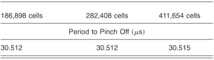
To test the grid dependence, we devised grids of total numbers 186,898, 282,408 and 411,654 cells adding 10% of the total grid points in each dimension. Tables1–3show the time at which the liquid thread pinches off from the nozzle outlet, the drop tip position, and the velocity of the drop head defined as a estimated velocity at the leading edge of the drop, as well as the volume of the primary drop using varied meshes. In this present study, the shape of the primary drop after the oscillation of the surface wave is sufficiently decayed by viscous dissipation could be ap-proximated to a sphere whose diameter is determined by measuring the maximum end-to-end distance of the liquid drop and could be used to estimate the drop volume. It is shown that the pinch-off times obtained with these three
meshes are in excellent agreement. Table2 shows the dif-ference in drop tip position where the velocity of drop head is estimated decreases with grid refinement. It is seen that the discretization error in drop tip position is around 0.43% when refining from 282,408 to 411,654 cells, whereas it is 1.04% when refining from 186,898 to 282,408 cells. In ad-dition, Table2 also presents that the discretization error in the estimated velocity of the drop head is around 2.28% between 282,408 and 411,654 cells, and that it is around 3.78% between 186,898 and 282,408 cells. Table3 makes clear that the difference in primary drop volume decreases with grid refinement. The computed error in drop volume at 40s when the shape of the primary drop could be ap-proximated to a sphere between 282,408 and 411,654 cells is around 1.49%, and that between 186,898 and 282,408 cells is around 6.11%. The net volumes of fluid expelling from the nozzle outlet over the total time period of simula-tion are 19.9982 pL on 186,898 grids, 19.5928 pL on 282,408 grids, and 19.6372 pL on 411,654 grids. The dif-ference in this net volume of fluid between 282,408 and 411,654 cells is 0.226% and that between 186,898 and 282,408 cells 2.07%. Therefore, grid independence is satis-fied with a mesh of 282,408 cells, achieving a compromise between accuracy and computing time, which in this paper is around 96 h of central processing unit 共CPU兲 time. As also illustrated in existing literature,40 note that when the primary drop moves downstream behind a certain simula-tion field, it does not conserve mass well. This may be due to the numerical grids with larger spacing arranged in this field and/or the linear order of the multidimensional unsplit advection algorithm with PLIC. The most effective remedy may be a careful attention to higher order schemes and sufficient grid resolutions. Figure4shows a comparison of the predictions with experimental observations of Yang et Table 1 Interval for a liquid thread from a nozzle outlet to pinch off,
with three meshes.
186,898 cells 282,408 cells 411,654 cells
Period to Pinch Off共s兲
30.512 30.512 30.515
Table 2 Velocity of the drop head with three meshes.
Time共s兲
186,898 cells 282,408 cells 411,654 cells
Head Velocity共m s−1兲 关Drop Tip Position 共m兲兴
15 5.81632共46.3兲 5.59234共45.9兲 5.66525共46兲 20 4.00525共70.7兲 4.15712共69.7兲 4.20037共70.3兲 25 2.97289共87.8兲 2.93412共87.1兲 2.83467共87.1兲 30.5 2.74526共103.1兲 2.75629共101.9兲 2.72694共102.5兲 35 3.09152共116兲 3.19418共114.9兲 3.25551共115.8兲 40 2.84138共131.3兲 2.58049共130兲 2.46021共130.1兲
Table 3 Primary drop volume with three meshes.
Time共s兲
186,898 cells 282,408 cells 411,654 cells
Primary Drop Volume共pL兲
30.5 8.94073 8.93109 9.081
40 6.89494 7.34343 7.45479
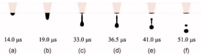
al.29of the temporal evolution of the position of the leading edge of the liquid drop. In this case, we used water as a working fluid whose density, viscosity, and surface tension are 1000 kg m−3, 1.0 cp, and 0.0725 N m−1, respectively. The corresponding parameters of the transducer pulse were set to be Ds= 0.029m, ⌬s= 3s, ⌬p1= 6.5s, Df = 0.058m,⌬f= 3s, ⌬p2= 3.5s, Db= 0.029m, and ⌬b= 3s. In addition, we excluded the first drop ejection from data analysis owing to an unbalanced liquid meniscus at the nozzle exit plane. Restricted to the limit of experi-mental setup configured by Yang et al.,29 the drop tip posi-tion was measured every 5s after the liquid thread emerged from nozzle outlet. This temporal resolution is in-sufficient to determine the evolution of ejected liquid dur-ing different stages of a piezoelectric actuator. However, based on the results shown in Fig.4, the numerical models predict the same trend as the experimental observation, and a reasonable agreement is obtained between the experiment and simulation. In addition, the comparison between the predictions and visualized images of evolution of ejected drop could be found in research of Yang et al.,29which used the theoretical models and arrangements of numerical grids similar to those used in this study.
3.2 Forward Stage
According to research of Dong et al.,16a typical DOD drop formation is divisible typically into six stages—ejection, stretching, necking, pinching off, recoil, and breaking up. Figure5shows these key stages observed in our numerical simulations. In the ejection stage, the liquid meniscus ini-tially protrudes from the nozzle orifice and then quickly extends outward due to the forward stroke of the
piezoelec-tric actuator关Fig.5共a兲兴. As the forward actuation ends, the
rate of liquid flow toward the plane of the nozzle exit rap-idly decreases during the period⌬p2; then some liquid is even sucked back into the nozzle under the effect of the backward actuator. A decreased rate of liquid flow toward the nozzle outlet would cause the difference in axial veloc-ity between the head of the liquid column and liquid near the plane of the nozzle exit. This velocity inequality ac-counts further for the stretching of the liquid column, as shown in Fig. 5共b兲. In addition, two necking points are observable during the stretching stage, first near the nozzle orifice and second near the bulbous head of liquid thread, as shown in Fig. 5共c兲. After a short interval, the tail of liquid thread pinches off from the nozzle outlet to form a freely flying liquid thread关Fig.5共d兲兴. The tail and the
lead-ing edge of the freely flylead-ing liquid thread are asymmetric and thus behave differently. Because the pressure at pinch-ing off is large, the tail of the free liquid thread begins to recoil toward the thread head and gradually evolves into a bulbous shape, as shown in Fig. 5共e兲. During the recoil stage, the second necking point continues to develop until the freely flying liquid thread breaks into two parts—a pri-mary drop and a secondary freely flying liquid thread with asymmetric ends. Because the secondary freely flying liq-uid thread retracts to the decrease of the surface energy, a satellite drop might be formed关Fig.5共f兲兴. This DOD drop formation with one satellite drop formed by end pinching might be found in most current simulations. In addition, two specific times could be observed in the drop formation process just described: pinching-off time when the ejected liquid thread detaches from the remaining liquid in the nozzle and breaking-up time when the primary drop is formed.
To investigate the effect of Df, ⌬f, and Wef on drop ejection, we conducted seven numerical experiments, as shown in Table 4. It is noticed that not all waveforms de-signed may assure the actuator of returning to the original position after the backward stokes are applied. This is so because to systematically examine the effects of compo-nents of a transducer pulse, all parameters are fixed except the one of interest in a numerical experiment. The disrup-tions of the fluid interface failed to occur in experiment 2, Fig. 5 Key stages observed in our numerical experiment 4:共a兲
ejec-tion,共b兲 stretching, 共c兲 necking, 共d兲 pinching off, 共e兲 recoil, and 共f兲 breaking up.
Table 4 List of experiments for the forward stage.
Experiment Ds 共m兲 ⌬ s 共s兲 ⌬ p1 共s兲 Df 共m兲 ⌬ f 共s兲 Wef ⌬ p2 共s兲 Db 共m兲 ⌬ b 共s兲 1 0.03 3 9 0.06 3 162.7 3.5 0.03 3 2 0.03 3 9 0.03 3 40.7 3.5 0.03 3 3 0.03 3 9 0.03 1.5 162.7 3.5 0.03 3 4 0.03 3 9 0.12 6 162.7 3.5 0.03 3 5 0.03 3 9 0.06 1.5 650.7 3.5 0.03 3 6 0.03 3 9 0.03 0.75 650.7 3.5 0.03 3 7 0.03 3 9 0.12 4.8 254.2 3.5 0.03 3
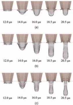
whereas experiment 1 with Df increased to 0.06m and experiment 3 with ⌬f decreased to 1.5s produced a pinching off of the liquid thread. It would appear that the ratio of Df to ⌬f must exceed a minimum value for a successful drop ejection. The value of Df/⌬fmultiplied by the area of the chamber wall adjacent to the piezoelectric material represents the rate of chamber volume displace-ment and could be related to the Weber number 共inertial/ surface tension force兲. For experiments 1, 2, and 3, Fig.6
shows the evolution of the liquid thread shape and velocity vector in the liquid side. On the effect of the backward stroke of actuation, the flow near the plane of the nozzle exit is reversed, which causes the formation of a stagnation plane sweeping toward the head of liquid thread. Figure
6共a兲shows that, under the conditions of experiment 2, the stagnation plane sweeps through the entire liquid thread and the thread fails to pinch off. Experiments 1 and 3, in contrast, show that the stagnation plane does not sweep to the liquid thread tip and the effect of the reversed flow causes necking near the nozzle and then the pinching off of the liquid thread, as shown in Figs. 6共b兲 and6共c兲. Figure
7共a兲shows the variation of the volume of the primary drop in these conditions. The drop volume in experiment 1 equals approximately that in experiment 5, and the drop volume in experiment 3 that in experiment 6; the drop vol-Fig. 6 Evolution of the liquid thread shape and velocity vector at the
liquid side in experiments共a兲 2, 共b兲 1, and 共c兲 3.
Fig. 7 Variation of共a兲 the volume of the primary drop and 共b兲 the velocity of the primary drop in experiments; the volume is in units of Rnoz3
= 5.044 pL and the velocity in units of Rnoz/ tca= 2.056 m s−1.
Fig. 8 Temporal variation of the rate of volume flow at the plane of the nozzle entrance in共a兲 experiments 3 and 6 and 共b兲 experiments 4 and 7.
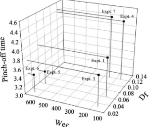
ume in experiment 4 is near that in experiment 7. The drop volume falls into three zones that correspond to three dis-tinguishable values of Df. Figure 7共b兲 shows the variation of the velocity of the center of mass of the primary drop on breaking up in these cases. The velocity of the primary drop increases substantially as Wef is increased, which corre-sponds to an increased inertial force. Experiments 1, 3, and 4 show that the drop velocity correlates positively with the primary drop volume; a similar relation is seen at different value of Wef, as shown in experiments 5 and 6 in agree-ment with the results of Feng.23This is so because the large amount of ejected liquid decreases the restoring effect of surface tension due to the smaller curvature of the fluid interface. Figure8shows the temporal variation of the rate of volume flow at the plane of the nozzle entrance. The total volume entering the nozzle during the forward stroke of the actuation in experiment 3 and representing the area underneath the line in Fig.8共a兲is 15.268 pL, whereas that in experiment 6 is 19.725 pL. Figure 8共b兲 shows that the total volume entering the nozzle during the forward actua-tion in experiment 7 is greater than that in experiment 4. These results indicate that through conservation of mass, the total volume ejected from the nozzle increases when the value of Wefincreases and that of Dfremains constant. The variation with experiments of duration of the liquid thread pinching off from the nozzle outlet is shown in Fig.9. The period for pinching off in experiment 3 is less than that in experiments 1 and 4. The period to pinch off seems to
increase as Df increases with Wef remaining constant; a possible explanation is that the large amount of ejected liq-uid corresponding to a large value of Df decreases the ef-fect of driving the breaking of surface tension by the small curvature of the fluid interface. As already mentioned, how-ever, the large ejected volume of liquid might weaken the restoring effect of surface tension and then result in a large forward momentum density, which facilitates the pinching off of liquid thread with a rapid elongation and necking, as shown in Fig.7共b兲. When Wef has a large value, the for-ward momentum density because of increased volume of ejected liquid increases greatly, as shown in Fig.7共b兲. The period to pinch off in experiment 5 is less than that in experiment 6 as the driving effect on pinching off through the increasing forward momentum density induced by in-creasing Df is dominant, as shown in Fig.9. Figure9also shows that the period for pinching off of the liquid thread in experiment 5 is less than that experiment 1. When Wef increases, the forward momentum density possibly in-creases, which accelerates the pinch-off of liquid thread by rapid elongation and necking, shown in Fig.7共b兲. A similar relation is found between experiments 3 and 6. However, Fig. 8 shows that, when the value of Wef increases, the ejected liquid volume increases, thus decreasing the effect of the driving of the breaking of surface tension and then decelerating the thread pinching off. Figure 9 shows that the period for pinching off in experiment 7 is greater than that in experiment 4 because the driving of the pinching off is contained by the increased volume of ejected liquid when Wef in experiment 7 is greater than that in experiment 4.
3.3 Backward Stage
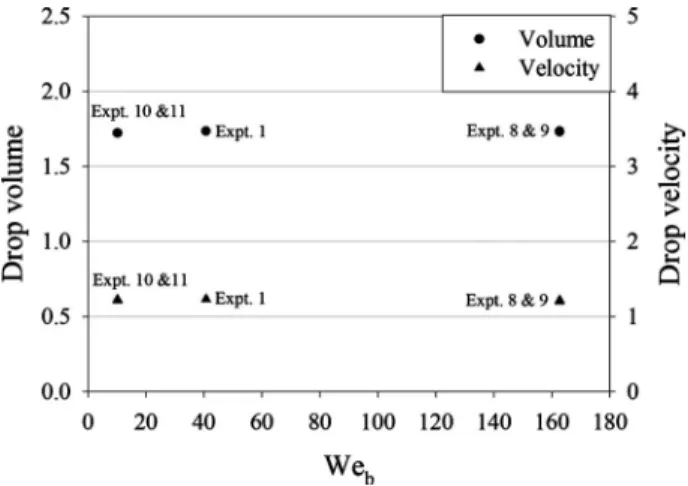
Table5 shows the variation of the conditions of the back-ward stroke in five numerical experiments for the investi-gation of the effect of Db,⌬b, and Webon the drop ejec-tion. Figure 10 shows the variation of the volume of the primary drop and the velocity of the center of mass of the primary drop upon breaking up in these experiments; the drop volumes are approximately constant in all cases. Moreover, the estimated values of the drop velocity in all experimental conditions fall into the same range. The back-ward inertial force in all these cases might be insufficient to draw all ejected liquid back and the meniscus would invade the tube through conservation of mass. Figure11shows the evolution of the shape of the liquid thread during the period Fig. 9 Variation with experiments of pinch-off time of liquid thread
from nozzle exit; the time is in units of tca= 8.341s.
Table 5 List of experiments for the backward stage.
Experiment Ds 共m兲 ⌬ s 共s兲 ⌬ p1 共s兲 Df 共m兲 ⌬ f 共s兲 ⌬ p2 共s兲 Db 共m兲 ⌬ b 共s兲 Web 1 0.03 3 9 0.06 3 3.5 0.03 3 40.7 8 0.03 3 9 0.06 3 3.5 0.06 3 162.7 9 0.03 3 9 0.06 3 3.5 0.03 1.5 162.7 10 0.03 3 9 0.06 3 3.5 0.03 6 10.2 11 0.03 3 9 0.06 3 3.5 0.06 12 10.2
of the backward stroke in the various experiments. The temporal variation of the tip position of the liquid thread for these cases is almost constant, and the contours of the liq-uid interface are similar, except near the plane of the nozzle exit. Under the effect of the reversed flow caused by the backward actuation, the liquid interface near the plane of the nozzle exit tends to be drawn back, and the mean cur-vature of the interface is negative and becomes smaller and smaller 共liquid surface near the nozzle exit is concave兲. Here, we assume that the principal curvature on the free surface is positive if the center of the circle of curvature lies on the liquid side. According to Eq.共8兲, the smaller the mean curvature at a point on the free surface, the larger the
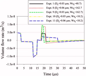
localized volume force induced by surface tension effect. After the period of the backward actuation terminates, the liquid in the nozzle would thus be pulled out again through the effect of the imbalance of surface tension and the inertia of the liquid in the ink-supply channel. The extent of tube invasion by the retracting meniscus and the acceleration of the thinning of the fluid neck increase as Webincreases共see Fig. 11, 18.5 and 19.5s兲. Experiment 8, in which the condition of the backward actuation has the same value of Web as in experiment 9 but a large working interval ⌬b shows a greater extent of tube invasion and a smaller cur-vature of the liquid interface, thus causing a larger rate of volume flow of the liquid toward the nozzle outlet. Figure
12shows the temporal variation of the rate of volume flow at the plane of the nozzle entrance. At the end of the back-ward stroke, the rate of volume flow at the plane of the nozzle entrance is directed toward the nozzle outlet and turns gradually into a still state. As already mentioned, ex-periment 8 has the rate of volume flow much less than experiment 9 because of the small curvature of the retract-ing meniscus. Experiment 11 is analogously expected to have a lesser rate of volume flow than experiment 10, as shown in Fig. 12. Figure13 shows the variation with ex-periments of duration of the liquid thread pinching off from the nozzle exit. Experiment 11 seems to have the smallest interval of pinching off. The backward actuation of experi-ment 11 might proceed through a considerable period in which pinching off of the liquid thread occurs before the rate of volume flow of the liquid toward the nozzle outlet begins because the surface tension is unbalanced. Experi-ment 8 appears to have large duration of pinching off be-cause the large rate of volume flow toward the nozzle outlet occurs behind the period of the backward stroke, as shown Fig. 10 Variation of the volume of the primary drop and velocity of
the primary drop in experiments; the volume is in units of Rnoz3
= 5.044 pL and the velocity in units of Rnoz/ tca= 2.056 m s−1.
in Fig. 12, therefore decelerating the thinning of the fluid neck and prolonging the pinching off. Distinct values of Web cause varied acceleration of the thinning of the fluid neck, which facilitates the thread pinching off. Various in-tervals⌬bof backward stoke along with various values of Web may cause varied extent of tube invasion, which ob-structs the thread pinching off by inducing the rate of vol-ume flow toward the nozzle outlet beyond the period of backward actuation. Experiments 1, 9, and 10 with differ-ent combinations of Weband⌬blead to the same duration of the thread pinching off, as shown in Fig.13.
3.4 Pause Stage
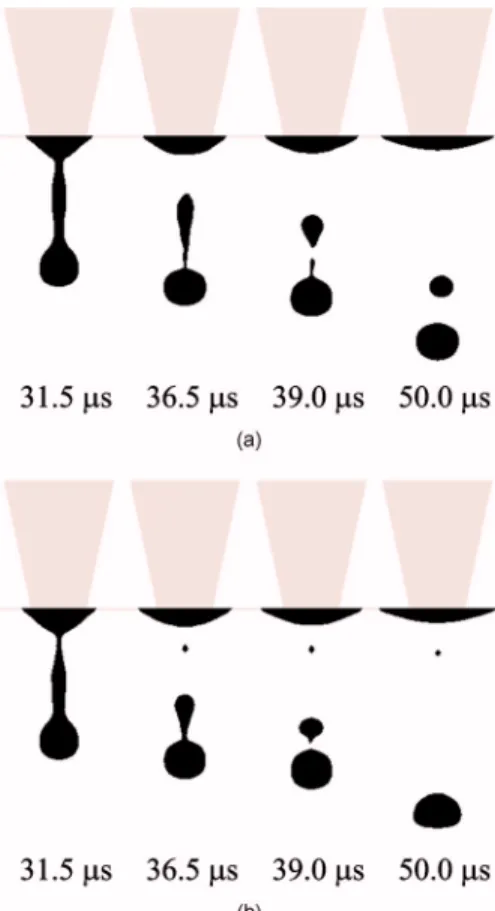
In an investigation of the effect of⌬p2on the ejection of a drop, Table6summarizes nine numerical experiments with various values of⌬p2. Figures14and15show the tempo-ral evolution of the shape of the liquid thread near the point of pinching off for experiments 1 and 12 and 8 and 15, respectively. After pinching off of the liquid thread occurs, experiment 12 shows that the tail of the freely flying liquid thread recoils toward the thread head, whereas experiment 1 shows one satellite drop to be formed by end pinching. Both experiments 8 and 15 show one satellite drop to be formed, but in the case of experiment 15, the satellite drop flies with a larger velocity than that of the former primary drop; the satellite drop might overtake and then merge with the primary drop. Among cases considered here, in experi-ments 12, 13, 16, and 17 there occurs no satellite drop. These results indicate that a decrease in⌬p2can damp the formation of the satellite drop; further investigations are described in the next section. Figure16shows the variation of the volume of the primary drop and the velocity of the center of mass of the primary drop upon breaking up in considered experiments. The volume of the drop is approxi-mately constant in all cases except experiments 12, 13, 16, and 17 with slightly larger drops. Moreover, other than ex-periments 12, 13, 16, and 17 with slightly larger drop ve-locities, all experiments show nearly the same estimated velocity. The tail of the free liquid thread might tend to Fig. 12 Temporal variation of the rate of volume flow.
Fig. 13 Variation with experiments of pinch-off time of liquid thread from nozzle exit; the time is in units of tca= 8.341s.
Table 6 List of experiments for the pause stage.
Experiment Ds 共m兲 ⌬共ss兲 ⌬共sp1兲 Df 共m兲 ⌬共sf兲 ⌬共sp2兲 Db 共m兲 ⌬共sb兲 1 0.03 3 9 0.06 3 3.5 0.03 3 12 0.03 3 9 0.06 3 1.75 0.03 3 13 0.03 3 9 0.06 3 0.8 0.03 3 8 0.03 3 9 0.06 3 3.5 0.06 3 14 0.03 3 9 0.06 3 1.75 0.06 3 15 0.03 3 9 0.06 3 0.8 0.06 3 9 0.03 3 9 0.06 3 3.5 0.03 1.5 16 0.03 3 9 0.06 3 1.75 0.03 1.5 17 0.03 3 9 0.06 3 0.8 0.03 1.5
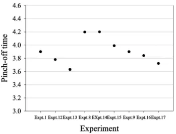
recoil toward the thread head, thus causing an increased volume and velocity of the drop. Figure17shows the varia-tion with experiments of duravaria-tion of the liquid thread pinching off from the nozzle exit. This duration decreases with decreasing⌬p2. For a decreasing period in which the flow rate toward nozzle outlet is reversed, the necking and then pinching off of the liquid thread from the nozzle outlet occurs early. Figure18shows the temporal evolution of the free surface contour of the liquid thread crossing the period of actuation of the backward stroke for experiments 1, 12, and 13. Compared to experiment 1, experiments 12 and 13 show an early necking of the liquid thread, because of the decreased pause stage. The temporal variation of the posi-tion of the thread head for these experiments is almost con-stant, as shown in Fig.18.
3.5 Suppression of Satellite Drops
The breaking up of freely flying liquid thread has two modes—multiple breaking up because of wavelike instabil-ity and end pinching, where the liquid thread pinches off from a bulbous end.16,41 The mechanism of end pinching may be a consequence of the fluid motion induced by cap-illary pressure gradients near the end of liquid thread.41The two modes of the breaking up of the free liquid thread could be observed in the presented simulations. The ex-amples of end pinching and multiple breaking up are found in Figs. 5 and 19, respectively. During multiple breaking up, a wavelike disturbance appears along the freely flying liquid thread. This disturbance grows until the liquid thread
breaks up at several places and varied times. The liquid thread in multiple breaking up tends to form numerous sat-ellite drops of varied size.
The breaking up of the freely flying liquid thread is re-lated closely to the length of the liquid thread at pinching off, which is defined as the distance between the leading-edge position and tail-tip position of the thread. In their DOD dispensing experiments Dong et al.16 observed that, for the freely flying water thread of small length at pinching off, the formation of a satellite results from end pinching Fig. 14 Temporal evolution of the liquid thread shape in
experi-ments共a兲 1 and 共b兲 12. Fig. 15 Temporal evolution of the liquid thread shape in
experi-ments共a兲 8 and 共b兲 15.
Fig. 16 Variation of the volume of the primary drop and velocity of the primary drop in experiments; the volume is in units of Rnoz3
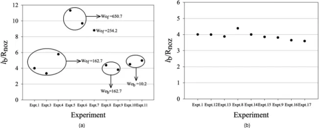
and for a long thread, a wavelike instability occurs and multiple breaking up is dominant. Figure 20 shows the variation with cases of liquid thread length at pinching off in the current simulations. For a ratio of thread length to nozzle radius共17.15m兲 greater than about 9.67, multiple breaking up occurs through a wavelike instability. When this ratio is smaller than 8.8, the breaking up becomes an end-pinching mode, as shown in Fig.20共a兲. In addition, the longer the length of liquid thread, the more satellite drops are formed. Experiment 5, for example, shows five satellite drops, experiment 6 three satellite drops, and experiment 7 two satellite drops. The thread length at pinching off is positively correlated with the value of Wef. With the same
value of Wef, an increased Df might yield an increased length of thread at pinching off. The causes of these phe-nomena might be that, when Wef increases, the forward momentum density increases, thus accounting for an in-creasing difference in axial velocity and then a more elon-gated thread. When Wefis constant, the larger Dfimplies a larger forward momentum density and then greater elonga-tion of the thread. A decreased⌬p2could slightly shorten the liquid thread length at pinching off by accelerating the rate of necking, shown in Fig.20共b兲.
To investigate further the effect of actuation conditions on the thread length at pinching off, we performed addi-tional experiments, as illustrated in Table 7. Figure 21
shows the variation in liquid thread length at pinching off for these experiments. The values of lb/Rnozin these cases
Fig. 17 Variation of duration of the liquid thread pinching off from nozzle exit; the time is in units of tca= 8.341s.
Fig. 18 Temporal evolution of the free surface contour of the liquid thread crossing the period of actuation of the backward stroke. Fig. 19 Satellite formation by multiple breaking up observed in nu-merical experiment 6.
are all above 9.67; the multiple breaking-up mode is then dominant. These results indicate that the varying param-eters in the pause and backward stages cause a slight varia-tion of thread length at pinching off. From the preceding discussion, we conclude that the thread length at pinching off from the nozzle outlet is governed mainly by the con-ditions of the forward stroke—Df and Wef.
In most applications, the satellite drops would degrade the printing quality or increase the difficulty of a precise microfludic control; for this reason, a suppression of satel-lite drops has considerable practical significance. As al-ready noted, the breaking-up mode of the freely flying liq-uid thread and its thread length at pinching off have been shown to be mutually positively correlated. In the end-pinching mode, the formation of a satellite drop seems to be predictable and its size is comparable. Several authors16,42–44 have suggested criteria to observe satellite formation by end pinching; for instance, the numerical re-search done by Notz and Basaran43 shows that the liquid thread with sufficiently large initial aspect ratio defined as the ratio of a half thread length to thread radius pinched off daughter drops from almost spherical ends by end pinching when Oh⬍O共0.1兲. In this study, the shape of the liquid thread was assumed to be a cylinder with hemispherical
caps at its two ends. In contrast, satellite drops caused by multiple breaking up tend to occur arbitrarily and have var-ied size.
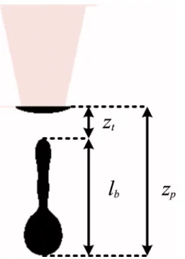
To investigate the suppression of satellite drops, we fo-cus our attention on the end-pinching breaking up of the freely flying liquid thread into the primary drop and the free secondary liquid thread. This secondary thread contracts into a single satellite drop. In the following analysis based on work of Dong et al.,16 we denote the pinching-off time as tb1, the breaking-up time as tb2, the thread length at pinching off as lb, the position as zt of the tail tip of the thread, the position zpof the leading edge of the thread, the average speed vr=储dzt/dt储tb2→tb1 of the retreating thread tail, and average speed vp=储dzp/dt储tb2→tb1 of the leading edge of the thread, as indicated schematically in Fig. 22. The freely flying liquid thread would contract into a single drop without satellite formation provided that the thread length at pinching off from the nozzle is less than a critical value lb*. If we denote the radius of this final single drop as rd,
lb− 2rd艋 共tb2− tb1兲共vr−vp兲. 共14兲
Scaling the period with the capillary time and the velocity with the capillary speed, we obtain
Table 7 List of additional experiments.
Experiment Ds 共m兲 ⌬ s 共s兲 ⌬ p1 共s兲 Df 共m兲 ⌬ f 共s兲 ⌬ p2 共s兲 Db 共m兲 ⌬ b 共s兲 5 0.03 3 9 0.06 1.5 3.5 0.03 3 18 0.03 3 9 0.06 1.5 0.8 0.03 3 19 0.03 3 9 0.06 1.5 0.8 0.03 1.5 20 0.03 3 9 0.06 1.5 0.8 0.03 0.75 21 0.03 3 9 0.06 1.5 0 0.12 3
Fig. 21 Variation of length of liquid thread at pinching off in various conditions.
Fig. 20 Variation of length of the liquid thread at pinching off with varied conditions in共a兲 the forward and backward stages and 共b兲 the pause stage.
tb1= c1tca, 共15兲
tb2= c2tca, 共16兲
vr= avca, 共17兲
in which c1, c2, and a are parameters, tca=共Rnoz
3 /兲1/2 is
the capillary duration, andvca=共/Rnoz兲1/2is the capillary
speed. By definition, c1is the ratio of pinching-off time tb1 to the capillary duration, c2is the ratio of breaking-up time to the capillary duration, and a is the ratio of retreating velocity to the capillary speed. In this study, the time scale is tca⬇8.341s and velocity scalevca⬇2.056 m s−1.
Sub-stituting Eqs.共15兲–共17兲into Eq.共14兲, we rewrite the equa-tion as
lb− 2rd艋 共c2− c1兲tcavcaa
冉
1 −vp vr
冊
. 共18兲
Replacing rdwith the radius of nozzle orifice and assuming thatvr⬎vp, we rearrange Eq.共18兲as
lb
Rnoz⬍ 共c2− c1兲a + 2 ⬅ lb* Rnoz
. 共19兲
Table8 presents this prediction in our simulations. Except for experiment 15, lb/Rnoz is larger than the critical value
lb*/Rnoz; then one satellite drop can be observed. Notice that
although the value lb/Rnozin experiment 15 is less than the
critical value lb*/Rnoz, the prediction in this case shows one
satellite formed; however, the lifetime of this satellite is quite short compared to experiment 8, as shown in Fig.15. One explanation for this is that to highlight the significant variables of the critical value lb*/Rnoz, we approximate the
radius of the final single drop rd as nozzle radius and ne-glect the term vp/vr in Eq.共18兲, which would slightly en-large the upper limits lb*/Rnoz. We can see in Table8 that
the ratio of the radius rp of the primary drop followed by one satellite-to-nozzle radius共17.15m兲 in experiment 15 is approximately 0.746, which can be expected to be slightly smaller than rd/Rnoz. From Eq. 共19兲, the critical
length of the thread at pinching off without formation of satellite drops depends mainly on c2, c1, and a. The value c2represents the time at which the primary drop is formed
through either end pinching or multiple breaking up. As recommended by Dong et al.,16c1and c2are closely related
to the liquid properties, nozzle radius, and the waveform of the transducer pulse. The variation of c2in our current
ex-periments is given in Fig.23and Table8. In experiment 1, c2is approximately equal to that in experiment 5 and c2in
experiment 3 to that in experiment 6. The value c2 in
ex-periment 4 is almost the same as that in exex-periment 7. Fig. 22 Schematic diagram of representative points during the
evo-lution of an ejected liquid thread.
Table 8 Liquid thread length at pinch-off compared with prediction.
Experiment C1 C2 a
vca
共m s−1兲
vp
共m s−1兲 r
p/ Rnoz lb/ Rnoz lb*/ Rnoz
1 3.899 4.559 2.635 2.056 2.38 0.745 4.0 3.739 4 4.378 5.217 2.501 2.056 2.443 0.949 5.773 4.099 8 4.197 4.617 2.721 2.056 2.511 0.745 4.385 3.143 9 3.899 4.498 2.833 2.056 2.4 0.745 3.813 3.698 10 3.898 4.858 2.259 2.056 2.56 0.744 4.501 4.169 11 3.719 4.859 2.298 2.056 2.546 0.744 4.974 4.618 14 4.2 4.62 3.263 2.056 2.426 0.751 4.0 3.371 15 3.99 4.65 3.004 2.056 2.433 0.746 3.848 3.983
These results indicate that c2 depends strongly on Df. The
relation between c1 and the waveform of the transducer pulse is shown in preceding sections. Compared to the ex-perimental results of Dong et al.,16the ratio of the average speed of the retreating thread tail to the capillary speed, as shown in Table8, ranges from 2.2 to 3.2 showing reason-able values. Note that in a few simulation cases, upon the pinching off of the liquid thread from the nozzle outlet, a tiny isolated liquid fragment called flotsam is observed. This flotsam is characterized by the vanishing velocity and size comparable to a single numerical cell. The appearance of the flotsam would interfere with the measurement of the retreating speed and the length of liquid thread at pinching off, and should be excluded from the data analysis. As al-ready noted, experiments 12, 13, 16, and 17 appear to show no satellite drop because the tail of the liquid thread con-tracts into the thread head. Experiments 12 and 13 show an interval tb1of pinching off smaller than in experiment 1. To estimate the critical value of experiments 12 and 13, we took c2= 4.559 and a = 2.635, as obtained in experiment 1
with the same value of Df, and because the value of a in experiments 14 and 15 is larger than that in experiment 8, as indicated in Table8. We thus obtain the critical thread length at pinching off lb*/Rnoz= 4.055, larger than lb/Rnoz
= 3.994 in experiment 12, in agreement with a prediction obtained from Eq.共19兲. An estimate of the value lb*/Rnozin experiments 16 and 17 is similarly obtained on taking c2
and a identical to values in experiment 9. Table9contains the estimate of a critical thread length lb*/Rnoz in
experi-ments 12, 13, 16, and 17. It is seen that a decrease in pause stage⌬p2could both shorten the liquid thread length lbat pinching off and enlarge the critical value lb*, thus damping the satellite formation.
Based on the analysis above and from Eq.共19兲, we pre-fer the larger c2, the smaller c1, and the larger a to induce
the larger lb*/Rnoz. The larger the value lb */R
noz, the wider
the range of liquid thread length at pinching off without satellite formation. As shown in Figs.23and9, both c1and c2appear to increase when Dfincreases with constant Wef.
An increase in Wef leads to a decrease in c1 when Df is
fixed, as shown in Fig.9. However, the larger Wef would cause the longer length lb/Rnozof liquid thread at pinching
off, which may contribute to the formation of satellite drops, as depicted in Fig. 20. Both lb/Rnoz and c1 tend to
decrease as the pause stage ⌬p2 decreases. According to research of Dong et al.,16 the interval between c1 and c2 increases when liquid viscosity increases, liquid surface tension decreases, or nozzle radius decreases. The param-eter a is shown not to be significantly related to the liquid surface tension, nozzle radius, and the waveform of the transducer pulse. However, as the liquid viscosity in-creases, the value of a would slightly increase. In conclu-sion, for a DOD drop generator with a given liquid, the Fig. 23 Variation of c2with experiments shown in Tables共a兲 4 and 共b兲 7.
Table 9 Estimate of the critical value of the thread length at pinching off.
Experiment C1 C2 tca 共s兲 a vca 共m s−1兲 l b/ Rnoz lb*/ Rnoz 12 3.78 4.559 8.341 2.635 2.056 3.994 4.055 13 3.63 4.559 8.341 2.635 2.056 3.878 4.449 16 3.84 4.498 8.341 2.833 2.056 3.644 3.869 17 3.721 4.498 8.341 2.833 2.056 3.592 4.206
waveform of transducer pulse could carefully be designed to obtain a longer tb2, a shorter tb1, and then larger upper limits lb*.
3.6 Supply, Refill, and Equilibrium Stages
To investigate the effect of Ds,⌬s, and Weson the liquid supply to the printhead, we performed five numerical ex-periments, shown in Table10. Figure24shows the tempo-ral variation of the position of the free surface along the center line of the nozzle in these cases. Upon initiation of the liquid supply, the flow in the nozzle and ink supply channel is directed toward the ink chamber having a vol-ume displacement caused by the altered dimensions of the piezoelectric actuator. Under the effect of the reversed flow, the meniscus near the nozzle outlet retracts and the mean curvature of the interface is negative and becomes smaller and smaller共liquid surface is concave兲. After the termina-tion of supply, the flow in the nozzle turns to the nozzle outlet through the effect of the imbalance of surface tension and inertia of the liquid in the supply channel in this so-called refill stage. According to the position of the free surface as a function of time shown in Fig.24, the rate of the retracting meniscus increases as Wesincreases. Experi-ment 26 reveals that, after 6s, the rate of the retracting meniscus decreases. The inertial force of the reversed flow
is gradually balanced by the restoring effect of the surface tension due to the smaller and smaller curvature of the liq-uid interface. Except for experiment 23, all numerical ex-periments show that the extent of invasion of the tube by the retracting meniscus is about 15m from the nozzle outlet. Moreover, Fig.24also shows that the period of the refill stage, which ends when the free surface along the nozzle center line reaches the nozzle exit plane, is approxi-mately 9s in these cases. Figure25shows the temporal variation of the rate of volume flow at the plane of the nozzle entrance. The rate of reversed volume flow increases as Wes increases. After termination of the ink supply, ex-periment 23 has a rate of volume flow less than exex-periment 24, whereas experiment 26 has a rate of volume flow less than experiment 25. The large extent of tube invasion caused by the retracting meniscus might account for the small curvature of the liquid interface, and then the larger restoring effect of surface tension to drive the flow toward the plane of the exit nozzle at the termination of ink supply. In most applications of microfluidic control, firing fre-quency, which represents the number of drops per second the printhead can dispense, determines the throughput or the speed at which an ink jet system can complete images. The firing frequency of printheads is equal to the reciprocal of the total time interval of a transducer pulse. In current study, the equilibrium stage⌬p3forms a large proportion of the transducer pulse and then its value determines the firing frequency of the printhead. To obtain stable drop for-mation, the value of⌬p3should be large enough to ensure the flow in the printhead of reverting to the initial condition for the next drop ejection. Figure26shows the variation of the primary drop volume and velocity with firing frequency by varying the value of⌬p3in experiment 1. Both varia-tion of drop volume and velocity are around 1% at a fre-quency of 4.348 kHz. When the firing frefre-quency increases to 15.625 kHz, the discrepancy of drop volume is still be-low 10%, yet the drop velocity is as large as 21.6%. From the results shown in Fig. 26, the firing frequency below 5 kHz appears to confirm the stable drop formation.
4 Conclusions
We conducted numerical simulations to investigate the ef-fect of actuation conditions on the drop ejection of a print-head共Picojet兲 of DOD type that is commercially available. Table 10 List of experiments for the supply stage.
Experiment Ds 共m兲 ⌬s 共s兲 Wes 22 0.03 3 40.7 23 0.06 3 162.7 24 0.03 1.5 162.7 25 0.03 6 10.2 26 0.06 12 10.2
Fig. 24 Temporal variation of the position of the free surface along the center line of the nozzle.
Fig. 25 Temporal variation of the rate of volume flow rate at the plane of the nozzle entrance.