J.-S. Wu
Phone: 886-3-573-1693 Fax: 886-3-572-0634 e-mail: [email protected]S.-Y. Chou
U.-M. Lee
Y.-L. Shao
Y.-Y. Lian
Department of Mechanical Engineering, National Chiao-Tung University, Hsinchu 30050, Taiwan
Parallel DSMC Simulation of a
Single Under-Expanded Free
Orifice Jet From Transition to
Near-Continuum Regime
This paper describes the numerical analysis of the flow structure of a single underex-panded argon free jet issuing into a lower-pressure or vacuum environment using the parallel three-dimensional direct simulation Monte Carlo (DSMC) method employing dynamic domain decomposition. Unstructured and tetrahedral solution-based refined mesh depending on the local mean free path is used to improve the resolution of solution. Simulated Knudsen numbers of the stagnation conditions based on orifice diameter, Rey-nolds numbers based on the conditions at the orifice exit, and stagnation-to-background pressure ratios are in the range of 0.0005–0.1, 7–1472, and 5 –⬁, respectively, where “⬁” represents vacuum condition in the background environment. Results show that centerline density decays in a rate proportional to the inverse of the square of the axial distance 共z−2兲 from the orifice for all ranges of flow in the current study. The more rarefied the background condition is, the longer the z−2-regime is. In addition, a distinct flow structure, including barrel shock, Mach disk and jet boundary, is clearly identified as the Knudsen number reaches as low as 0.001. Predicted location and size of Mach disk in the near-continuum limit (Kn= 0.001, 0.0005) are found to be in reasonable agreement with experimental results in the continuum regime. 关DOI: 10.1115/1.2062807兴
Introduction
Many industrial processes requires the use of high-speed under-expanded jets to either provide impulse or deliver the interested gas species to the designated region or provide high-density cool-ing to specific heated wall共due to small area of jet impingement and higher velocities of impact兲. Practical examples include the use of jets for rocket exhausts at high altitude and attitude control on satellite, cooling of Micro-Electro-Mechanical-Systems 共MEMS兲 devices, fine particle deposition and removal, in inkjet printing technology, showerhead共periodic array of microjets兲 for materials processing, among others关关1兴, and the reference cited therein兴. The nozzle used to generate the under-expanded jet can be either a simple thin sonic orifice or converging-diverging 共La-val兲 nozzle 关2兴. The latter design can create uniform supersonic jets with desirable flow properties. For example, one such prop-erty is a highly uniform pressure along the centerline of the jet that extends many nozzle diameters downstream共inviscid poten-tial core兲. Of course, this design may also present some significant drawbacks, including difficulties of manufacturing and high noise level. Previous studies have shown that these drawbacks may be removed if the nozzle is miniaturized关2兴. However, manufactur-ing this kind of nozzle is not straightforward at all.
On the other hand, thin sonic orifice, having a minimum cross-sectional area at the exit, represents the simplest type of micro-nozzle. One of the obvious advantages of using the orifice lies upon the simplicity of manufacturing and maintenance. This type of orifice generates an underexpanded sonic jet if the pressure ratio of chamber to background is approximately larger than 2, which is often the case in practical applications. However, the axial pressure distribution resulting from the orifice microjet var-ies significantly within the first few orifice diameters. The inviscid
potential core of the supersonic jet dissipates and the resulting subsonic flow decays rapidly, which may be advantageous for mixing purpose. The situation is even more complicated due to rarefaction if the background environment is at low-pressure or near-vacuum. Thus, understanding of the flow characteristics of the free orifice underexpanded sonic jets is important when apply-ing them to these practical situations.
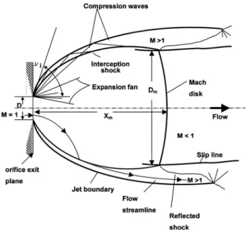
A single underexpanded orifice jet issuing into a quiescent en-vironment has been studied extensively in the past, but most stud-ies were either emphasizing upon the experimental visualization of the flow structure关关3,9兴, and references cited therein兴 or simple analytical solution关4,5兴. Very few simulation studies were done, especially when rarefaction effects are considered关12兴. The main features of the continuum free jet in the near field include a Mach disk, barrel shock and free jet boundary 关1兴. Behind the Mach disk, subsonic core and supersonic outer flow are bounded by a slip line, which emanates from the triple point. The triple point is the intersection location of barrel shock and Mach disk. The barrel shock intersects with the Mach disk and then reflects as an oblique shock.
Several theoretical researches关4,5兴 studied the flow structures, especially the diameter or location of the Mach disk. However, there is no satisfied analytical method available to predict the entire structure of an underexpanded sonic jet. Numerical solu-tions using method of characteristics关6,7兴 predicted the inviscid jet boundary and the intercepting shock, but were generally not able to predict the formation of Mach disk. Instead, experiments using flow visualization were able to capture the location and diameter of the Mach disk. Ashkenas and Sherman关8兴 measured the Mach disk position using electron beam visualization in the continuum limit. They proposed a well-known correlation as xM/ D = 0.67共p0/ pb兲1/2, where x
Mis the Mach disk position, p0is the source pressure, and pbis the background pressure. Later, in the same group of Sherman 关9兴, they measured the Mach disk position and diameter of a highly underexpanded sonic jet, con-sidering high-pressure ratios, high stagnation pressures, tempera-ture variations and geometries of solid boundary in the nozzle lip
Contributed by the Fluids Engineering Division for publication in the JOURNAL OF
FLUIDSENGINEERING. Manuscript received by the Fluids Engineering Division March 5, 2004; final manuscript received: June 26, 2005. Associate Editor: Fernando Grin-stein.
Journal of Fluids Engineering Copyright © 2005 by ASME NOVEMBER 2005, Vol. 127 / 1161
region. Results showed that Mach disk location was insensitive to the variations of共a兲␥, 共b兲 condensation, 共c兲 nozzle lip geometry, 共d兲 absolute pressure level.
Muntz et al. 关10兴 proposed a rarefaction parameter D共popb兲1/2/ T
0to classify the structure of a free jet expanding into a region of finite background pressure. This rarefaction parameter is in fact proportional to the inverse of共po/ pb兲1/2Kn, which com-bines the effects of pressure ratio and rarefaction. The structures of free jet can be classified into three flow regimes: continuum, transition, and scattering, according to the degree of continuum to rarefied upstream. In this scattering flow regime, any evidence of continuum gas dynamic features disappears关2兴. In this regime, the shock envelope has completely vanishes and the gas density smoothly passes to the background density through scattering
pro-cess. Only the DSMC method关11兴 is capable of simulating such flow field, although it is well known that it is very computational expensive. Usami and Teshima 关12兴 did an experiment using mass-sampling technique for mass flow measurements in an un-derexpanded orifice jet. Flow field was then simulated by the DSMC method and reasonable agreement was found as compared with experiments, although the treatment of outflow boundary conditions is problematic due to the assumption of mean zero velocities in the DSMC simulation and near-uniform mesh. It is rather difficult to simulate this type of flow field since the density varies very much from the orifice to the outer boundaries, which makes the selection of both the time-step size and cell size very challenging in the DSMC simulation.
In summary, numerical studies along this line are relatively few or unsatisfied, especially the rarefaction effects caused by the low-pressure stagnation condition and low-low-pressure background, in which the N-S equations break down. In addition, the flow may reach hypersonic speed ahead of the Mach disk共or highly thermal nonequilibrium兲 for larger pressure ratio, which makes the simu-lation using N-S equation difficult. Thus, in the current study we shall use the DSMC method to systematically study the flow structure of the underexpanded sonic jets at different flow condi-tions with Knudsen numbers in the range of 0.0005–0.1 and Rey-nolds numbers in the range of 7–1472, both defined using orifice size and upstream stagnation conditions of pressure and tempera-ture 共Fig. 1兲. Transition to turbulence is not considered in the current simulation due to the low Reynolds-number flows. Simu-lated results are then compared with experimental data available in the literature.
The paper begins with descriptions of numerical method and procedures共Table 1兲. Then, results are presented along with ap-propriate discussions. Finally, conclusions of this study are pre-sented.
Numerical Method and Procedures
In the current study, the single under-expanded free jet flow is intrinsically axisymmetric. However, the three-dimensional DSMC code was used instead of the axisymmetric DSMC code because of the following two reasons. First, it is well known that the accuracy near the axis deteriorates if the cell size becomes small 共thus, small cell volume兲 due to insufficient samplings,
Table 1 Corresponding values of the rarefaction parameter for test conditions Fig. 1 Flow structure of a single under-expanded orifice jet in
which often contradicts with the requirements of spatial resolu-tion. In addition, position-based 共e.g., radial兲 particle 共or cell兲 weighting关11兴 used to remove this inaccuracy often induce other problems, such as random walk, whose effect is hard to evaluate before simulation. However, use of the three-dimensional DSMC code will naturally remove this constraint, although the computa-tional load is higher than the axisymmetric DSMC code in es-sence. Nevertheless, it can be relieved to greater extent by taking the advantage of the symmetric conditions and efficient parallel processing, which will be shown clearly later. Second, maintain-ing both the axisymmetric and three-dimensional DSMC codes can be very time-consuming and tedious. Especially, we are inter-ested in applying this 3D code to compute multiple jet interaction in the near future. The DSMC method and the parallel DSMC code共PDSC兲 关13兴 used in the current study are described as fol-lows in turn.
The DSMC Method. The direct simulation Monte Carlo method共DSMC兲 关11兴 is a particle method for the simulation of gas flows. The gas is modeled at the microscopic level using
simulated particles which each represents a large number of physi-cal molecules or atoms. The physics of the gas are modeled through the motion of particles and collisions between them. Mass, momentum and energy transports are considered at the par-ticle level. The method is statistical in essence. Physical events such as collisions are handled probabilistically using largely phe-nomenological models, which are designed to reproduce real fluid behavior when examined at the macroscopic level. General pro-cedures of the DSMC method consist of four major steps: moving, indexing, collision and sampling. In the current study, we use VHS molecular model 关11兴 to reproduce real fluid behavior as well as no time counter共NTC兲 关11兴 for the collision mechanics. Since monatomic gas 共argon兲 is simulated, no energy-exchange model is required. Details of the procedures and the consequences of the computational approximations regarding DSMC can be found in Bird关11兴.
The Parallel DSMC Method. In the present study, we have utilized the previous developed Parallel three-dimensional DSMC Code 共PDSC兲 关13兴, which features unstructured adaptive mesh Fig. 2 Flow chart of the parallel DSMC method „PDSC… with mesh
refinement
Journal of Fluids Engineering NOVEMBER 2005, Vol. 127 / 1163
refinement 关14,17兴, parallel implementation on memory-distributed machines using dynamical domain decomposition 关15,16兴, variable time-step method 关13,17兴, and boundary-pressure iterative scheme关19兴. Details of all features of the PDSC can be found in these references and will be only briefly described here for completeness, considering the specific application in the cur-rent study.
Overall computational procedures of the PDSC can be summa-rized schematically in Fig. 2. The parallel DSMC method is implemented on an unstructured tetrahedral mesh using the par-ticle ray-tracing technique关17,18兴, which takes the advantage of the cell connectivity information. Variable time-step approach is used by enforcing mass, momentum and energy conservations when simulation particles cross the interface between cells 关13,17兴. Mean velocities and temperatures at the outflow bound-aries can be obtained by iteratively enforcing the specified pres-sure boundary conditions关19兴. During the simulation, the mesh h-refinement technique共adding local grid points兲 with cell-quality control is used to repeatedly improve the cell distribution accord-ing to the solution, based on some adaptation criteria 共for ex-ample, “density” in the current study兲 关13,14兴. Multilevel
graph-partitioning technique关20兴 is used to dynamically redecompose the computational domain to balance the workload among proces-sors关15,16兴. Stop at Rise 共SAR兲 关21兴 scheme is used to determine when to repartition the computational domain by defining a deg-radation function, which represents the average idle time per time step for each processor including the cost of repartition. Commu-nication of particle data between processors only occurs when particle hits the inter-processor boundary, while communication of cell data only occurs when repartitioning the domain takes effect. Data for communication is sent and received as a whole to reduce the communicational time between processors.
The current parallel code, in the Single Program Multiple Data 共SPMD兲 paradigm, is implemented on the parallel memory-distributed system, e.g., PC-cluster system共one master processor and 23 slave processors with each having 2.4 GHz AMD, 0.5 G RAM, and Giga-bit ethernet in our laboratory兲. This code is highly portable since the standard message-passing interface 共MPI兲 is used to communicate information among processors. Re-sults presented in the following are obtained using 23 processors unless otherwise specified.
Results and Discussions
Before the detailed discussion of computational results the single orifice jet interested in the current study, we would like to mention that the parallel DSMC code关13兴 that we are using has been verified for a parallel twin-jet interaction at similar Knudsen number共Kn=0.00385兲 by comparing well with the experimental data in Ref.关13兴. This nevertheless justifies our usage of the par-allel DSMC code关13兴.
Flow Conditions and Simulation Conditions. A single jet, issuing into a chamber region at specified background pressure, is simulated in the current study. Monatomic argon gas is used as the
Table 2 Simulation conditions for Kn= 0.0005
Table 3 List of computing domains for Kn= 0.0005 and 0.001
Fig. 3 Surface mesh and its isodensity distribution on a 1 / 16-domain of a single jet„Kn=0.001, PR=150… „initial: 149, 168 cells; level-2: 1,109,411 cells…
working gas to preclude any complexities caused by the energy exchange among internal degrees of freedom. Orifice size used for generating the under-expanded free jet is 500m in diameter. Uniform sonic flow condition at the exit of the thin orifice is assumed, although viscous effects may be present in this low Reynolds-number flow regime that we are interested in. However, it is well known that for highly underexpanded free jets, the high supersonic region only weakly depends on the transonic condi-tions at the orifice关8兴. Thus, inviscid gas dynamics 共quasi-1D兲 is used to define the exit conditions at the orifice using the assump-tion. Parametric studies, varying Knudsen numbers 共Kn =upstream/ dorifice兲 in the range of 0.0005–0.1 and stagnation-to-background pressure ratios共PR=p0/ pb兲 in the range of 5–⬁, are considered. Corresponding upstream 共stagnation兲 pressures and temperature are in the range of 107– 21,446 Pa and 300 K, re-spectively. Pressure and temperature at outflow boundaries are fixed as specified background pressure and 300 K, respectively.
Resulting Reynolds number defined using the conditions at the orifice exit is in the range of 7–1472, which is very low as com-pared with previous studies关8兴 that considered the macro jets in the continuum regime共upstream兲. Thus, the possibility of transi-tion from laminar to turbulence is not considered in the current simulation.
We first run some typical cases共at same Knudsen number兲 to observe if the steady state is reached by observing if the total number of particles is approximately constant. We then decide the number of time steps 共iterations兲 required to reach steady state conservatively by putting some safety factor, e.g., 2–3 times the number of iterations to reach approximate constant particle num-bers. For convenience, we often use the same number of iterations 共time steps兲 for representing the transient periods at different pres-sure ratios for the same Knudsen number. We believe this should be safe for all the cases considered that steady state has been reached for sampling.
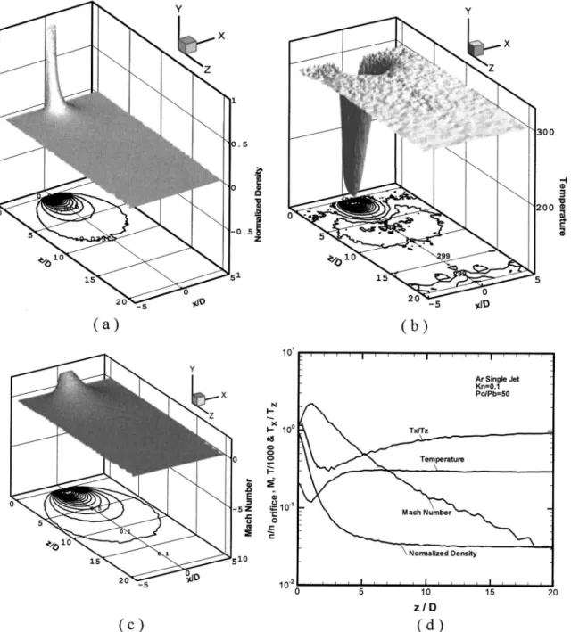
Fig. 4 Properties distribution at Kn= 0.1, PR= 50 of underexpanded argon jet„y=0 plane… „a… normalized
den-sity;„b… temperature; „c… Mach number; „d… data along centerline
Journal of Fluids Engineering NOVEMBER 2005, Vol. 127 / 1165
Typical refined unstructured mesh at the final level 共level-2兲 along with the distribution of isodensity is shown in Fig. 3共Kn = 0.001, PR= 150兲. It clearly shows that the mesh is automatically refined near the high-density regions. In this specific case, the number of cells increases from 149,168 cells initially to 1,109,411 cells at level-2 mesh refinement. Total number of particles in this case is approximately 10 millions. Resulting number of particles per cell is on the order of 10, except in the region near the orifice exit共⬃2兲. In general, the number of simulated particles is in the range of 0.1 million 共Kn=0.1, PR=⬁兲 to 19 million 共Kn = 0.0005, PR= 250兲, while the number of time steps 共iterations兲 for sampling is about 34,000 for each case. Detailed simulation con-ditions for the most challenging case共Kn=0.0005兲 are listed in Table 2. The number of particles used in this Kn= 0.0005 case is on the order of 10 million. The reference time step共1E-10兲 rep-resents the smallest time step used in the computational domain due to the high-density region, thus, very small cell, near the exit of the orifice. The mean velocities at the outer boundaries are obtained during the simulation by iteratively enforcing the speci-fied pressure that uses the concept of flux conservation through the boundaries, which is similar to that in关19兴. Temperatures at the outflow boundaries are set as 300 K. Since the flow is axisym-metric, only 1 / 16 of the physical domain is considered, where the
specular boundary condition is imposed on each of the sliced plane. Results using this sliced domain are found to be in excel-lent agreement with those using full domain. In general, the larger the pressure ratio is, the larger the computational domain is re-quired. Detailed sizes of computational domain for Kn= 0.0005 and Kn= 0.001 at different pressure ratios are listed in Table 3 for reference. In the following, we will discuss the effects of pressure ratio and rarefaction on the general flow structures, when present-ing the simulation results.
Effects of Pressure Ratio
Kn= 0.1. Before looking into the effects of pressure ratio, we first present the typical distributions of the normalized density, temperature and Mach number at the sliced plane共y=0兲 that are illustrated in Figs. 4共a兲–4共c兲, respectively, for Kn=0.1 and PR = 50. Centerline distribution of the above parameters共up to z/D = 20兲 along with the ratio of thermal nonequilibrium 共Tx/ Tz兲 is also shown together in Fig. 4共d兲 for the convenience of compari-son. Results at this flow condition show that the density mono-tonically decreases very rapidly outward in all directions from the orifice exit due to the lower pressure in the background共⬃0.03 of the value at the orifice exit兲. Temperature decreases due to rapid expansion near the orifice region, reaching as low as 12 K at
Fig. 5 Centerline normalized density, temperature, velocity, and Mach number distributions at different pres-sure ratios„Kn=0.1…
z / D⬇1, and then increase to the specified background tempera-ture, 300 K, at z / D⬇5. Mach number increases up to 2.2 at about the same location 共z/D⬇1兲 and then decrease down to 0.1 at z / D⬇20. The ratio of thermal nonequilibrium deviates from unity in the near orifice region with a value of 0.3 at z / D = 2.5, which shows a strong thermal nonequilibrium exists in this flow due to rapid expansion.
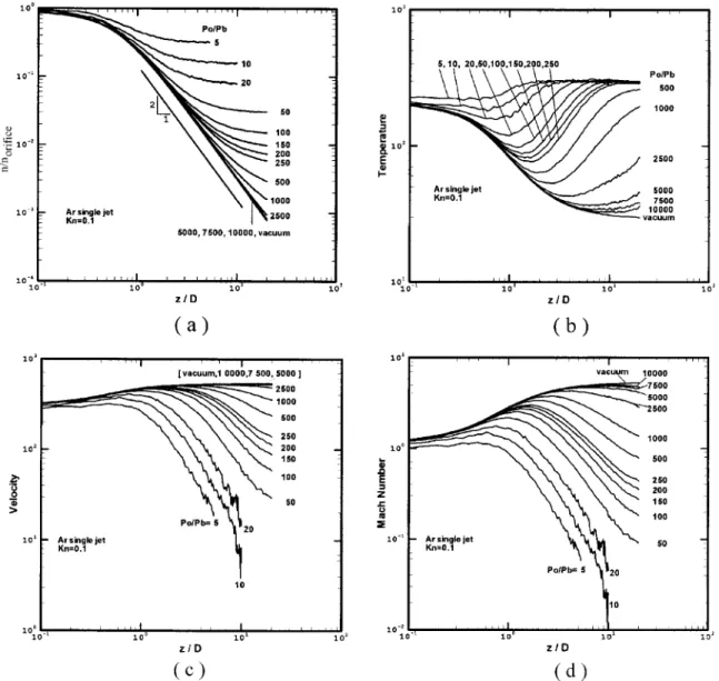
Figures 5共a兲–5共d兲 show the effects of pressure ratio to the cen-terline distributions of normalized density, temperature, velocity, and Mach number, respectively, at Kn= 0.1, which is in the tran-sitional regime. Pressure ratio in the current study is in the range of 5 –⬁, which ensures the choke condition at the orifice exit. In general, density 关Fig. 5共a兲兴 decreases monotonically along the centerline to the background value as expected. For example, the density at x / D = 20 decreases down to 0.1% of the value at the orifice exit for PR艌5,000. In addition, normalized density data
along the centerline can be fitted as n / norifice= 0.24共z/D兲−2 for PR艌5,000 in the current simulation range 共z/D艋20兲, which is nearly the same as that obtained experimentally关8兴. Note that the axial distance, where the −2-slope decay holds, begins at x / D ⬇1. In Fig. 5共b兲, temperature generally decreases first along the centerline due to expansion and then increases to the background temperature. Minimum temperature is in the range of 30– 220 K for PR in the range of⬁–5. Generally, the axial distance, where the minimum temperature reaches, increases with increasing pres-sure ratio. In Fig. 5共c兲, centerline velocity generally increases at first and then decreases further downstream. Faster decrease in the downstream is found for lower pressure ratios, which is retarded by the existence of density background gas. For higher-pressure ratios, the centerline velocity stays at nearly constant value all the way downstream 共PR艌5,000兲. In Fig. 5共d兲, Mach
Fig. 6 Properties distribution at Kn= 0.001, PR= 50 of argon jet„y=0 plane… „a… normalized density; „b… temperature;
„c… Mach number; „d… data along centerline
Journal of Fluids Engineering NOVEMBER 2005, Vol. 127 / 1167
number along the centerline generally increases to supersonic speed at first due to expansion and then decreases to low subsonic speed at far downstream for lower pressure ratios. It can be found that the change of Mach number with respect to the downstream location is generally larger than the centerline velocity because the speed of sound also varies depending on translational temperature. Note that maximum Mach number is in the range of 1.2–5 for PR in the range of 5 –⬁. Axial distance, where the maximum Mach number reaches, also increases with pressure ratio. In general, the above results show that at this Kn= 0.1 the larger the pressure ratio, the more the gas expansion from the orifice into the back-ground.
Kn= 0.001. Typical property distributions共normalized density, temperature and Mach number兲 at the sliced plane 共y=0兲 along with the centerline property distributions in the near-continuum regime共Kn=0.001兲 are illustrated in Figs. 6共a兲–6共d兲, respectively. Unlike the case in the transitional regime共Fig. 4兲, a distinct cell-like flow structure, including shock and expansion waves, begins to appear. Results show that the density decreases very rapidly in the streamwise direction from the orifice exit and is approximately 1%, of the value at the orifice exit, at z / D⬇5. It then increases up to 6%, of the value at the orifice exit, at z / D⬇7 due to the for-mation of a thickened Mach disk. After this, the density decreases and increases again repeatedly, although the amplitude of
alterna-tion becomes smaller. In addialterna-tion, a barrel shock circulating the core region that prevents the penetration of background gas into the core region. Due to rapid gas expansion, temperature de-creases down to 15 K at location before the thickened Mach disk, and then increases to 300 K after the thickened Mach disk. It then follows the similar trend as the density variations afterwords. As for Mach number, it increases up to hypersonic speed共7.3兲 before the thickened Mach disk共z/D⬇4.5兲, and drops to very low sub-sonic speed 共0.07兲 right after the thickened Mach disk 共z/D ⬇5.5兲. In Fig. 6共d兲, it also shows the ratio of thermal nonequilib-rium共Tx/ Tz兲 along the centerline. Results show that strong ther-mal nonequilibrium exists near the Mach disk location with a value of 0.3 due to strong compression of gas molecules across the shock, whose data can only be simulated using particle method as in the current study. In addition, strong thermal non-equilibrium also appears near the lips of the orifice due to rapid gas expansion, although it is not shown in the current report. In general, the cell-like flow structure begins to appear explicitly with several thickened shock structure at this near-continuum re-gime共Kn=0.001兲. The structure will be more observable as rar-efaction is reduced. Comparison of the simulated Mach-disk po-sition and diameter with experimental data in the near-continuum regime will be discussed later.
Figures 7共a兲–7共d兲 illustrate the effects of pressure ratio 共PR
Fig. 7 Centerline normalized density, temperature, velocity and Mach number distributions at different pres-sure ratios„Kn=0.001…
= 5 –⬁兲 to the centerline distributions of normalized density, tem-perature, velocity and Mach number, respectively, at Kn= 0.001, which is in the near-continuum regime. Again the density de-creases rapidly along the centerline before the appearance of the Mach disk and scales as n / norifice= 0.24共z/D兲−2 starting at z / d ⬇1, which is nearly the same as the case in Kn=0.1. However, Mach disk either disappears or becomes unrecognizable when PR艌2500 probably due to the very rarefied flow 共low background pressure兲 at the very downstream. We have extended the region of simulation up to z / D = 120 for larger pressure ratios and have found the Mach disk is not clear at all. This more or less can be explained or correlated by using a rarefaction parameter, which will be shown shortly. Increase of the density across the Mach disk is generally the same in the range of 6–7 times for pressure ratios in the range of 10–500关Fig. 7共a兲兴, except the case of PR = 5, in which it increases only approximately 2.5 times. For the smaller pressure ratios共PR=5,10,20兲 the repeated cell-like struc-ture is comparatively clear in Figs. 7共a兲–7共d兲, while it is smeared for the case of larger pressure ratio, which may be due to the limit of simulation domain or very lower density level at the far down-stream. In addition, one distinct feature in this near-continuum regime共Kn=0.001,0.0005兲 is the temperature and Mach number scale approximately as 共z/D兲−5/4 关Fig. 7共b兲兴 and 共z/D兲3/4 关Fig. 7共d兲兴, respectively, before the Mach disk, which is not seen in the transitional regime共Kn=0.1,0.01兲. Detailed reasons resulting in these special scalings require further study. It may be due to the formation of the shock structure consisting of barrel shock and Mach disk, which prevents the penetration of background gas into the expansion region near the orifice exit. In Fig. 7共c兲, centerline velocity generally increases at first, then decreases rapidly across the Mach disk and finally increase and decrease alternatively fur-ther downstream, depending on the pressure ratios. The maximum velocity in this alternative oscillation is generally smaller than the velocity before rapid decrease. It is also found that the maximum rapid decrease of centerline velocity occurs at PR= 50 in the cur-rent study. Centerline Mach number changes much more pro-nouncedly due to the change of centerline temperature, which is similar to the case of Kn= 0.1 as presented in Fig. 5.
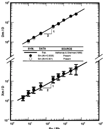
Figure 8 presents the comparison of the Mach-disk position and diameter, respectively, between the simulation in the near-continuum regime共Kn=0.001,0.0005兲 and the experimental cor-relation in the continuum limit 关8,9,22兴. Correlations of Mach-disk position and diameter were determined experimentally as XM/ D = 0.67共Po/ Pb兲1/2 关8兴 and DM/ D = 0.24共Po/ Pb兲1/2 关9兴, re-spectively. Due to the thickened Mach disk in the near-continuum regime, there are uncertainties in determining the accurate posi-tion, and especially the diameter, of the Mach disk. Nevertheless, we have defined the position of the Mach disk by locating where the minimum value of the density is. Uncertainty bars are in-cluded for the Mach-disk position in the figure for reference, while it is not shown for the Mach-disk diameter due to the dif-ficulty of deciding the uncertainties. Nevertheless, we have mea-sure the radial position at the Mach disk, where the density is maxima, as the Mach-disk position. Results show that the simu-lated data at Kn= 0.001 and 0.0005 in the near-continuum limit are in reasonable agreement with the experimental correlation of Ashkenas and Sherman关8兴 in the continuum limit, considering the uncertainties as mentioned in the above. Similar agreement can also be found for the Mach-disk diameter as a function of the pressure ratio in Fig. 8.
Figure 9 shows the comparison of the radial profiles of normal-ized density for Kn= 0.1 and Kn= 0.001 at different positions 共PR=5,000兲 in the inviscid core, with a simple density cosine-square scaling proposed by Ashkennas and Shermann关8兴 based on their experimental data. Results show the accuracy of the simple density scaling deteriorates with increasing axial position, al-though the simple scaling law always predicts a wider radial den-sity profile in general. Reason for the discrepancy requires further
Fig. 8 Position and diameter of Mach disk as a function of pressure ratio for a single argon underexpanded jet
Fig. 9 Comparison of the radial profiles of normalized density at different positions at„PR=5000…
Journal of Fluids Engineering NOVEMBER 2005, Vol. 127 / 1169
investigation. Flow at Kn= 0.001 expands more quickly than that at Kn= 0.1 at the same pressure ratio. Similar trends can be found for larger pressure ratios before the Mach disk if it exists.
In Muntz et al. 关10兴, they proposed a rarefaction parameter = D共p0pb兲1/2/ T0 describing the combined effects of rarefaction and pressure ratio. It is interesting to know the correspondence between this parameter and the cases simulated cases simulated in the current study. Table 1 shows the resulting values for all the simulated cases. Equivalently, previous results can be illustrated using this rarefaction parameter and are shown in Fig. 10. Results clearly show that the cell-like structure共or the Mach disk兲 begins to appear asⲏ0.3 and larger. For ⱗ0.3 the flow can be catego-rized as the scattering regime as described in关10兴.
Conclusions
A parallel three-dimensional DSMC method using unstructured solution-based adaptive tetrahedral mesh is used to study flow structure of a single underexpanded argon free jet from transi-tional to near-continuum regime. In the transitransi-tional regime, gas flowing out of the orifice continues to expand to background con-dition if the pressure ratio is large. Otherwise, it expands first and then compress to the ambient value. In the near-continuum re-gime, a distinct cell-like flow structure begins to form similar to those obtained in previous experimental study in the continuum regime. Results of simulated Mach-disk position and diameter in the near-continuum regime are in reasonable agreement with pre-vious experimental correlation in the continuum regime. In addi-tion, highly thermal nonequilibrium both occurs across the Mach disk in the near-continuum regime and near the orifice for rapid gas expansion in the transitional regime. One last comment the authors would like to make is the statistical noise near the orifice exits, especially for the cases of Kn= 0.0005 and Kn= 0.001,
which is the near-continuum regime. Thus, the fidelity of the data very near the orifice exit may be in doubt in the current study. From the computational viewpoint, N-S equations should be used in this high-density region instead of the DSMC method, which necessitates the hybrid of the DSMC method and the N-S solver. Preliminary progress toward this goal will be reported elsewhere 关23兴.
Acknowledgments
The authors would like to express their sincere thanks to the computing resources provided by the National Center for High-Speed Computing of National Science Council of Taiwan. In ad-dition, financial support by National Science Council of TAIWAN 共NSC91-2212-E-009-045兲 is also highly appreciated.
References
关1兴 Phalnikar, K. A., Alvi, F. S., and Shih, C., 2001, “Behavior of Free and Im-pinging Supersonic Microjets,” AIAA Paper No. 2001-3047.
关2兴 Scroggs, S. D., and Settles, G. S., 1996, “An Experimental Study of Super-sonic Microjets,” Exp. Fluids, 21, pp. 401–409.
关3兴 Adamson, T. C., Jr., 1964, “The Structure of the Rocket Exhaust Plume With-out Reaction at Various Altitudes,” Supersonic Flow, Chemical Processes and
Radiation Transfer, Pergamon, New York.
关4兴 Young, W. S., 1975, “Derivation of the Free-Jet Mach-Disk Location Using the Entropy-Balance Principle,” Phys. Fluids, 18, pp. 1421–1425.
关5兴 Eastman, D. W., and Radtket, L. P., 1963, “Location of the Normal Shock Wave in the Exhaust Plume of a Jet,” AIAA J., 1, pp. 918–919.
关6兴 Owen, P. L., and Thornhill, M. A., 1948, “The Flow in an Axially-Symmetric Supersonic Supersonic Jet From a Nearly Sonic Orifice Into a Vacuum,” Aero-nautical Research Council, ARC Technical Report No. RM-2616.
关7兴 Love, E. S., Grigsby, C. E., Lee, L. P., and Woodling, M. S., 1959, “Experi-mental and Theoretical Studies of Axisymmetric Free Jets,” NSNA TR R-6. 关8兴 Ashkenas, H., and Sherman, F. S., 1966, “The Structure and Utilization of
Supersonic Free Jets in Low Density Wind Tunnels,” Rarefied Gas Dynamics,
Fourth Symposium, Vol. II, Academic, New York, pp. 84–105.
关9兴 Crist, S., Sherman, P. M., and Glass, D. R., 1966, “Study of the Highly Under-Expanded Sonic Jet,” AIAA J., 4, pp. 68–71.
关10兴 Muntz, E. P., Hamel, B. B., and Maguire, B. L., 1970, “Some Characteristics of Exhaust Plume Rarefaction,” AIAA J., 8, pp. 1651–1658.
关11兴 Bird, G. A., 1994, Molecular Gas Dynamics and the Direct Simulation of Gas
Flows, Oxford University Press, New York.
关12兴 Teshima, K., and Usami, M., 1997, “An Experimental Study and DSMC Simu-lation of Rarefied Supersonic Jets,” 20th International Symposium on Rarefied
Gas Dynamics, C. Shen, ed., Bejing University Press, Beijing, pp. 567–572.
关13兴 Wu, J.-S., Tseng, K.-C., and Wu, F.-Y., 2004, “Parallel Three-Dimensional DSMC Method Using Mesh Refinement and Variable Time-Step Scheme,” Comput. Phys. Commun., 162共3兲, pp. 166–187.
关14兴 Wu, J.-S., Tseng, K.-C., and Kuo, C.-H., 2002, “The Direct Simulation Monte Carlo Method Using Unstructured Adaptive Mesh and Its Application,” Int. J. Numer. Methods Fluids, 38共4兲, pp. 351–375.
关15兴 Wu, J.-S., and Tseng, K.-C., 2003, “Concurrent DSMC Method Using Dy-namic Domain Decomposition,” 23rd International Symposium on Rarefied
Gas Dynamics, A. Ketsdever and E. Muntz, eds., AIP Conf. Proc. 663, pp.
406–413.
关16兴 Wu, J.-S. and Tseng, K.-C., 2005, “Parallel DSMC Method Using Dynamic Domain Decomposition,” Int. J. Numer. Methods Eng., 63, pp. 37–76. 关17兴 Kannenberg, K. C., 1998, “Computational Method for the Direct Simulation
Monte Carlo Technique With Application to Plume Impingement,” Ph.D. the-sis, Cornell University, Ithaca.
关18兴 Wu, J.-S., and Lian, Y.-Y., 2003, “Parallel Three-Dimensional Direct Simula-tion Monte Carlo Method and Its ApplicaSimula-tions,” Comput. Fluids, 32共8兲, pp. 1133–1160.
关19兴 Wu, J.-S., Lee, Fred, and Wong, S.-C., 2001, “Pressure Boundary Treatment In Micromechanical Devices Using The Direct Simulation Monte Carlo Method,” JSME Int. J., Ser. B, 44共3兲, pp. 439–450.
关20兴 Walshaw, C., Cross, M., and Everett, M., 1997, “Parallel Dynamic Graph Partitioning for Adaptive Unstructured Meshes,” J. Parallel Distrib. Comput.,
47, pp. 102–108.
关21兴 Nicol, D. M., and Saltz, J. H., 1988, “Dynamic Remapping of Parallel Com-putations With Varying Resource Demands,” IEEE Trans. Comput., 39共9兲, pp. 1073–1087.
关22兴 Mirels, H., and Mullen, J. F., 1963, “Expansion of Gas Clouds and Hypersonic Jets Bounded by a Vacuum,” AIAA J., 1, pp. 596–602.
关23兴 Wu, J.-S., Lian, Y.-Y., Gary Cheng, and Roy Koomullil, 2005, “Development of a Parallel Hybrid Method for the DSMC and NS Solver,” AIAA 43rd Aerospace Sciences Meeting and Exhibit, Reno Hilton, Jan, pp. 10–13.