i
國
立
交
通
大
學
資訊科學與工程研究所
碩
士
論
文
利用相對定位系統來增進無線區域網路之位置隱私
Enhancing Location Privacy in WLAN using Relative Positioning
System
研 究 生:邱青波
指導教授:謝續平 教授
ii
利用相對定位系統來增進無線區域網路之位置隱私
研究生: 邱青波 指導教授: 謝續平 博士
國立交通大學資訊科學與工程研究所碩士班
摘 要
目前使用者的位置隱私在不同的環境中都有遭受威脅的可能。在無線
區域網路的環境中,攻擊者可以透過使用者不會改變的網路卡實體位
置來達到追蹤的目的。雖然目前有很多相關的研究被提出來克服這個
問題,由於這些相關研究並未把附近移動裝置的移動行為列入考量,
因此這些目前的解決方案會錯過許多可以改善使用者位置隱私的理
想時機,也就是這些現行方案對於找到理想的網卡位置更新時機是有
困難的;此外,這些現行方案會有頻繁的無用網卡位置更新動作發生。
因此,在這篇論文中,我們提出一個以相對定位技術為基礎的方案,
透過分析每位使用者的移動行為來提高位置隱私。我們的方案藉由讓
每個移動裝置去蒐集彼此的訊號強度,並週期地將這些資訊送到特定
的伺服器作移動行為分析並決定哪些移動裝置需要更新網卡實體位
置。由實驗結果,我們的方案確實有效地減少使用者被追蹤的時間。
iii
Enhancing Location Privsacy in WLAN using
Relative Positioning System
Student:Ching-Po Chiu Advisor:Dr. Shiuhpyng Shieh
Department of Computer Science
National Chiao Tung University
Abstract
A user’s location privacy can be threatened in many different environments. In WLAN,
an adversary can track a user through his/her unchanged MAC address. Although
previous schemes were proposed to combat this issue, they do not take the mobile
behavior of neighboring nodes into account. Therefore, these schemes may miss the
opportune moment to update MAC address, i.e. they have difficulty determining the
ideal time to change MAC addresses. Furthermore, they suffer from unnecessary
MAC address updates. In this thesis, we propose a relative-positioning based scheme
to enhance user’s location privacy by analyzing the mobile behavior of each user. This
scheme requires the mobile station associated with the same access point to collect
the signal strength of others, and then periodically send to a centralized server for
determining the stations to update MAC addresses. The experiment results showed
that our scheme effectively reduces the duration of time that a user can be tracked in
comparison to prior works.
Keywords
iv
誌
謝
會有這篇論文的誕生,真的必須要感謝、感恩身邊許多人的協助,
沒有你們,呵~我應該會無法寫出這個自己生平的第一篇論文,由衷
地感謝你們,真的!如果在誌謝中,沒看到名字的朋友,並不是因為
你們不重要或是礙於篇幅,而是我已經把我對你們的感謝放在心中
了。
首先,對於指導教授 謝續平博士,誠摯地感謝這兩年來的指導,
一直扮演亦師亦友的角色,不管是生活上的協助,亦或研究上的指導
都讓我深感這兩年生活著實地豐富,謝謝!再來,對於一進到實驗室
時當時的碩二學長們:Jelly、厚坤、阿力、野狗、渥人,你們總是
在我無助時適時地伸出援手,讓我再再地感受到人情味實驗室的溫暖;
另外,對於博班學長也著實地感謝你們在論文最後衝刺階段的協助,
讓我可以撐了過來,特別感謝子逸學長,每次在我遇到瓶頸時都挺身
而出地給我一些想法,讓我可以再次看見曙光。對於實驗室可愛的學
弟妹們,也要謝謝你們有意沒意地打氣,哈~與你們在實驗室的這一
年,很開心!嗯~DSNS Lab, I love you all!
最後,我要感謝我的家人,在我求學路上一直默默地支持著我,
讓我可以無掛慮地完成學業;另外,也要感謝我的最愛,迪皮還有妳,
v
Table of Contents
1. Introduction ... 1 1.1 Background ... 1 1.2 Motivation ... 4 2. Related Work ... 7 2.1 Overview ... 7 2.1.1 Dynamic-based Schemes ... 7 2.1.2 Unlinkable Scheme ... 82.1.3 Mitigating Network-Overhead Scheme ... 9
2.1.4 User-Centric Scheme ... 9
2.2 Comparison... 10
3. Proposed Scheme ... 11
3.1 The Consideration of Design ... 11
3.2 System Topology ... 14
3.3 System Architecture ... 16
3.4 Detailing the Complicated Phase ... 18
3.4.1 Signal Collection Phase ... 18
3.4.1 Update Judgment Phase ... 19
4. Evaluation ... 27
4.1 Simulation Setup ... 28
4.2 Simulation Result and Analysis ... 29
5. Conclusion. ... 32
vi
List of Tables
Table 1-1 the accuracy of different location determination methods ... 2
Table 2-1 summarizes the previous works ... 10
Table 3-1 Notations ... 15
List of Figures
Figure 1-1 illustrate the different confused levels at different update time . 5 Figure 3-1 Topology of Proposed Scheme ... 13Figure 3-2 the overview of scheme ... 16
Figure 3-3 An example for illustrating the relative positioning algorithm ... 21
Figure 3-4 illustrating the Mobile-Immobile case ... 24
Figure 3-5 illustrating the Mobile-Mobile case ... 26
Figure 4-1 illustrating which users will be picked as target ... 29
Figure 4-2 CDF of tracking time ... 30
Figure 4-3 Comparison of maximal tracking round ... 31
1
1. Introduction
In this thesis, we focus on mitigating the problem of location privacy in wireless
local area network (WLAN) and the problem was caused at the link/physical layer, i.e.
the adversary tracks a particular user through the clues of MAC address and signal
strength. The remainder of this chapter is organized as follows. First, in Section 1.1
we will give the background of location privacy according to current related
researches. Finally, we introduce our motivation in Section 1.2.
1.1 Background
Today, the rapid development of wireless communication makes our life more
convenient. For example, you can receive and send e-mail anywhere without the
wired restriction, or find the nearest restaurant through the location based service
(LBS). However, the broadcast nature of wireless medium makes a malicious
adversary has the ability to track a user through an unchanged value. Hence, most
wireless networks suffer from the threat of location privacy, such as RFID, Bluetooth,
GSM, WLAN [11, 12, 15]. Basically, the location-privacy issue mainly focuses on how
to prevent other malicious parties from learning one’s current or past location
information [13]. But perfect privacy is nearly impossible as long as communication
occurs. Therefore, the research of location privacy is toward minimizing the
information disclosed [14].
In WLAN, if we want to protect user’s location privacy, we should first know the
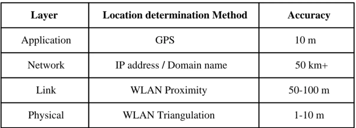
disclosed level of location information in each layer of OSI model. From Table 1-1 [16],
we can know that the most accurate location information is either included at the
2
Table 1-1 the accuracy of different location determination methods
Location determination Method Accuracy
GPS
IP address / Domain name
WLAN Triangulation 10 m 1-10 m 50 km+ WLAN Proximity 50-100 m Layer Application Network Link Physical
It is unnecessary to doubt that the more accurately a user can be positioned, the
higher threats the user might suffer. Therefore, many schemes were proposed for
mitigating this problem. As far as the application layer is concerned, while a user
needs LBS, he must tell the LBS provider his current location to achieve this goal.
Therefore, the user’s location information is explicitly included in the frame. If the
user takes location privacy as his first priority, he can simply provide the ambiguous
location information for the LBS provider [17]. Basically, this might be a tradeoff
between location privacy and the correctness of LBS, and the user can actively
prevent third parties from knowing his exact location. However, the broadcast nature
of the link/physical layers allow an adversary can track a user through eavesdropping
user’s signal strength and MAC address. Hence, compared the application layer with
the link/physical layer, the later is in a passive position for resisting adversary’s
tracking.
Next, we point out why WLAN suffers from serious threats of location privacy, and
list the following reasons to describe respectively:
The proliferation of hotspot
Due to the cost of deploying WLAN infrastructure is relative lower than GSM
3
malicious network operator can easily deploy many access points to cover the
area which an adversary is interested in. So the adversary can track a particular
user in his deploying area. In other words, the user might be tracked as long as
his communication occurs no matter whether the user connects to the
adversary’s WLAN infrastructure or not.
Insecure 802.11 frame header
Basically, the 802.11 encryption algorithms only encrypt the frame body but
the frame header is kept in plaintext format. However, the frame header
includes the fields of the sender’s and receiver’s MAC address. Therefore, if an
adversary knows the relation between user identity and MAC address, the user
can be tracked through the known MAC address.
Pervasive computing is entering our life
With a rapid increase in mobile devices integrated with WLAN interfaces and
the proliferation of many emerging techniques (VoWLAN, LBS, etc.) that take
advantage of this architecture, more and more people will likely carry a mobile
device anywhere he goes. Therefore, when an adversary can track a mobile
device, it indicates the adversary can track the person through the mobile
device.
Accurate positioning system
Due to the radio properties of WLAN is short-range transmission. Hence, you
can roughly estimate the sender’s position as long as you can receive the
sender’s frame. In other words, the distance between you and the sender is
small than transmission range (about 100 meters). If more accurate positioning
system is adopted, the accuracy can be raised to 1~10 meters [6, 18]. Certainly,
the more accurately a user can be positioned, the higher threat of location
4
1.2 Motivation
As mentioned previous, the WLAN environment suffers from the threat of location
privacy, and it results in the adversary can track a user through his/her unchanged
MAC address. Therefore, many schemes were proposed to mitigate this problem [1,
2, 3, 5]. All the schemes allow mobile stations to update their MAC address to avoid
the attacker’s tracking. However, the approach in [1] enables mobile stations to
update their MAC addresses only at specific time instances (e.g. before associating
with access points) and the paper [2] mitigates the correlations between old and new
MAC address through adding a silent period during MAC address update. Basically,
the mobile stations can not transmit during the silent period. And the work [3]
mainly focuses on mitigating the network overheads resulted from adopting these
works [1, 2]. Finally, the approach in [4] enables a mobile station to update only
when changing his velocity or direction.
Although previous schemes mitigate the adversary’s tracking possibility, they do
not take into account the mobile behavior of neighboring nodes. Thus, these
schemes have difficulty determining the ideal time to change MAC addresses and
may miss the opportune time to update. Furthermore, they suffer from unnecessary
MAC address updates. Because these useless updates occur, it results in time-
wastage including re-association time and interface update time. Therefore, we
propose a scheme to enhance a user’s location privacy by analyzing the mobile
behavior of its neighbors.
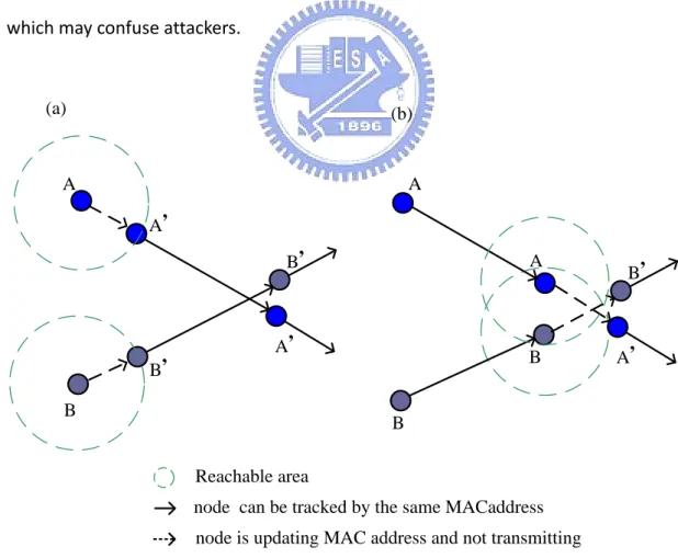
In order to understand our motivation more clearly, we illustrate the situation
which previous works do not take into account in Figure 1-1. In Figure 1-1 we
consider the scenario: two mobile stations (A and B) are tracked by an adversary. The
5
In this case, node A will change to new MAC address A’ and node B will change to
MAC address B’. Besides, in order to mitigating the possibility that the adversary link
the new MAC address to old one, we assume the two nodes will not transmit any
frame during silent period. And the attacker will estimate possible reachable area for
each node according to the previous velocity of each node. We use the dashed circle
to represent the estimated reachable area. Therefore, in Figure 1-1 (a) we discover
this update is useless for both A and B. This is because there is not any overlap
between A’s reachable area and B’s. So this update will not make the adversary
confused. Nevertheless, if the two nodes update their MAC address at an opportune
time (e.g. Figure 1-1 (b)), the update will make the adversary confused. Because we
cannot limit the mobile behavior, what we can do is finding out the opportune time
which may confuse attackers.
A B B, A, A, B,
node is updating MAC address and not transmitting node can be tracked by the same MACaddress
A B A, B, A B (a) (b) Reachable area
6
Therefore, the motivation of this thesis is to design a scheme for protecting user’s
location privacy from being disclosedto the attacker with tracking ability. In addition,
the goal of our study is toward reducing both the number of useless update and the
opportunities for location tracking.
The rest of the thesis is organized as follows. In Chapter 2, we briefly introduce the
previous works which focus on mitigating the location tracking at the link/physical
layer. Next, we detail our proposed scheme in Chapter 3 by describing the
consideration of design first, giving the overview of our scheme and detailing each
phase. In addition, we analyze the improvement of adopting our scheme and also
compare with the previous works in Chapter 4. Finally, we give a conclusion of our
7
2. Related Work
In this Chapter, we introduce the current research of location privacy, and focus on these works which provide the protection of location privacy at the physical/link layer. Due to previous works possess the inherited property, i.e. most of the later works will take the previous works as necessary components. Thus, in section 2.1 we briefly introduce the details of each work by proposed time-order. Finally, we will compare these works in section 2.2.
2.1 Overview
According to the main feature of previous works, we classify them into four classes:
Dynamic-based scheme, Unlinkable scheme, Mitigating network overhead scheme
and User-Centric scheme. In addition, we introduce them in proposed time-order.
2.1.1 Dynamic-based Schemes [2003, 2006]
According to the pool size of MAC address, the dynamic-based schemes can be
further divided into two subclasses as follows.
Disposable approach [1]
The scheme enhances the location privacy through shorted-lived, disposable
MAC addresses and the disposable address is generated by a MD5 hash chain on a
random seed. In other words, the new MAC address is randomly chosen from the
pool of 248 MAC addresses. And this scheme enables mobile stations to update their MAC addresses only at specific time instances (e.g. before associating with access
8
access points, and tracks a user’s movement only through the association log of
each access point. Thus, the threat-level of location privacy is only within the
coverage of some access point. If an attacker tracks a user through RSSI/TOA-based
tracking methods, the scheme will not resist the attack effectively. However, we
should take into account such more accurate tracking method.
SWAP approach [5]
The SWAP approach enables the nodes to exchange their MAC addresses. Thus,
the pool size of SWAP approach is far smaller than Disposable approach. SWAP
approach has the following advantages. First, the approach does not need all the
nodes to update their MAC addresses at the same time. Compared with Disposable
approach, the SWAP approach could achieve the same ambiguous effect with fewer
nodes participated in this update. Finally, the SWAP approach does not need any
MAC address collision detection, but the approach takes many efforts for the
communication of exchange identity.
2.1.2 Unlinkable Scheme [2005]
Basically, the unlinkable scheme utilizes Silent Period to decrease the opportunities
that an adversary links the new MAC address to old one [2]. The Silent Period is a
variable length transition period in which a user is not allowed to disclose either the
old pseudonym or the new one. Due to the adoption of silent period, the possibility
of both the spatial and temporal correlation attack can be reduced. Because the
unlinkable scheme makes the attacker eavesdrop nothing during silent period, the
attacker has no idea about the exact movement of target. Basically, the temporal
attack occurs, while an adversary links the new MAC address to old one through
9
two nodes (A and B). In addition, the average durations of update-time are 2 seconds
and 3 seconds for node A and B respectively. Assume that the two nodes update
their MAC address at the same time, and then the adversary can break this update
through the difference A’s average duration of update-time and B’s (i.e. 1 second).
The spatial correlation attack occurs, while an adversary link the new MAC address to
old one through analyzing the past velocity and direction. Although this scheme
provides more protection than disposable scheme, it also makes the user unable to
access the WLAN for longer time. Therefore, it is the tradeoff between location
privacy and performance.
2.1.3 Mitigating Network-Overhead Scheme [2006]
The mitigating network-overhead scheme [3] attempts to minimize the network
disruption as a result of adopting disposable MAC addresses. Defrawy et al. claim
that the re-association process with the AP may take up to 2.5 seconds, and this
process degrades the user’s throughput. Therefore, the scheme takes the advantage
of features derived from Mobile IP and utilizes a trusted centralized server to
mapping the incoming and outgoing packets to the mobile station by the NAT-like
approach. Through the cooperation between the centralized server and mobile
stations, these mobile stations can effectively mitigate the overhead of re-association
process for each MAC address update. However, the tracking attack which the
scheme can resist is the same as Disposal scheme, i.e. both of them cannot
effectively resist the RSSI/TOA-based tracking methods.
2.1.4 User-Centric Scheme [2006]
Mingyan et al. claim that each user may need privacy at different locations and
10
independently determine where/when to update their identifiers. The scheme
assumes that each mobile station has GPS capability and can self-determine its
location when needed on pre-loaded digital geographic maps, and is also capable of
predicting any change in its velocity. So each station updates its MAC address only
when its velocity or direction changes. However, the assumption mentioned above
heightens the threshold of improving location privacy because of requiring additional
hardware cost, i.e. GPS. In addition, it might be not so reasonable and convenient to
request a pedestrian to input the destination for each move.
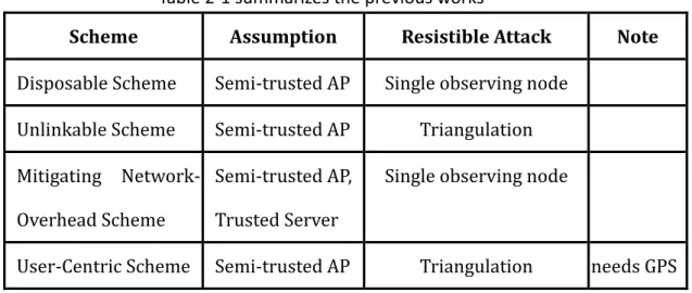
2.2 Comparison
In this section, we use Table 2-1 to summarize the previous works briefly. Basically,
all the previous schemes assume the access point is semi-trusted, i.e. forward packes
as expected but can disclose information to an adversary. In addition, Both the
Disposal Scheme and Mitigating Network-Overhead Scheme only resist such attack
with single observing node. In other word, they can not effectively resist
triangulation-based tracking. However, the Unlikable Scheme and User-Centric
Scheme can effectively resist location tracking with triangulation-based techniques.
Table 2-1 summarizes the previous works
Scheme Assumption Resistible Attack Note
Disposable Scheme Semi-trusted AP Single observing node Unlinkable Scheme Semi-trusted AP Triangulation
Mitigating Network- Overhead Scheme
Semi-trusted AP, Trusted Server
Single observing node
11
3. Proposed Scheme
In this chapter, we propose a relative-positioning based scheme which enhances
user’s location privacy through analyzing the mobile behavior of user’s neighboring
nodes. Basically, the goal of our work is to design a system for protecting user’s
location privacy from being tracked through triangulation technique in WLAN. In
order to achieve this goal, there are severaldesign details we must consider. Hence,
the remainder of this section is organized as follows. First, Section 3.1 presents the
design challenges we must overcome, and give some ideas used to overcome these
challenges. Next, Section 3.2 gives the topology of our system. Then, we will talk
about the architecture of our system in Section 3.3. Finally, Section 3.4 discusses the
details of each phase in our system.
3.1 The Consideration of Design
Our proposed scheme considered the following design issues, and the first one is a
main goal for each scheme with dynamic MAC address. In addition, the others are
our additional considerations for providing more efficient protection.
Unlinkable MAC Address
In order to prevent attacker’s tracking through an unchanged MAC Address, we
must adopt dynamic-based MAC Address scheme [1, 5] as a part of our system.
In addition, we also combine the silent period [2] with our scheme to make the
MAC Address unlinkable. Basically, silent period is defined as a transition period
between using new and old MAC address in which a station is not allowed to
12
similar to the adversary’s as possible as we could, the station can update its
MAC address at opportune time. Therefore, we refer to relative positioning
system [4] for helping us update MAC address at opportune time.
Decrease Useless Update
Because every update of MAC Address will be an overhead, decreasing useless
updates will improve performance for any dynamic-based MAC Address scheme.
Once we can know the moving behavior of neighboring station, decreasing
useless update will become possible. Compared with current works [1, 2, 3, 5]
that not take the moving behavior of neighboring station into account, we believe
that our system could decrease useless update to a certain extent.
Low Cost
Due to the deployment of Access point always take maximal coverage into
account with minimal number of AP for low-cost purpose. Consequently, if we
adopt absolute positioning system to help us take our view similar to the
adversary’s, it needs at least three fixed observing nodes to achieve this goal for
one BSS (Basic Service Set). Furthermore, if we use additional hardware, such as
GPS, to help us know the moving behavior, it’s actually an additional cost.
Whether absolute positioning system or GPS, both of them heighten the
threshold of improving location privacy, and this is one of the reasons why we
adopt the relative positioning system rather than absolute positioning system.
Location Privacy
In general, the amount of location privacy disclosure depends on whether the
13
prevent when possible or minimize a user’s location privacy from being
disclosed to an untrustworthy third party. For a trusted third party, we should
control the level of a user’s location privacy disclosure; therefore, we can reduce
the damage to the user in the event that the trusted third party is compromised. In
addition, the US Federal Communications Commission has mandated that, by
December 2005, all cellular carriers be able to identify the location of emergency
callers using mobile phones to within 50 to 100 meters [20]. Hence, if we adopt
the same requirement in WLAN, the trusted network operator should know the
access point which a mobile user currently associates with. The reason is that the
WLAN proximity is about 100 meters. Therefore, this is another reason why we
adopt relative positioning system rather than absolute positioning system.
In such considerations mentioned above, we proposed a cooperative scheme to
enhance user’s location privacy and achieve the foregoing considerations. In our
scheme, we let the stations which associate with the same access point to collect
the signal strength of others, and then periodically send the information to the
centralized server for determining which nodes have to update.
Privacy Coordinator (PC)
Access Point (AP)
Mobile Station Mobile Station Mobile Station Figure 3-1 Topology of Proposed Scheme
14
3.2 System Topology
Our system contains three different kinds of node (Figure 3-1), and we respectively
introduce their function as follows:
Privacy Coordinator (PC) :
A trusted centralized server for computing relative coordinates of each station
and making a decision of changing MAC Address. In WLAN environment, It
generally needs an AAA server for security of enterprise-level. Therefore, we can
combine the PC into an AAA server for cost concern. But for WLAN without AAA
server, it is the only additional cost. Compared with absolute positioning system
and GPS, such cost is relative low. Basically we only need one PC to serve many
BSS.
Access Point (AP):
Its functionality is nothing different from general AP. Basically, it’s responsible
for forwarding frames between mobile stations and wired network. Therefore,
we assume such AP is semitrusted, i.e. operate as expected but can disclose
information to an adversary. In Addition, we define a special type of AP, called
Ref AP, which is used for mobile station to determine itself whether mobile or
not. If a mobile station associate with a specific AP, Ref APs are those APs whose
packets can be received by the station in the same channel. Ref APs might be
depolyed by the same network operator or different one.
Mobile Station (MS) :
All the MSes have to do is collecting signal strength of each MS associated with
the same AP and send the information to the PC periodically. Besides collecting
15
which includes Ref APs (if they exsits) and the AP associated by the MS.
Therefore, the PC will know the mobile behavior of MS by through these signal
information, and has the ability to do some judgements. Further, find better
timing to update MAC address.
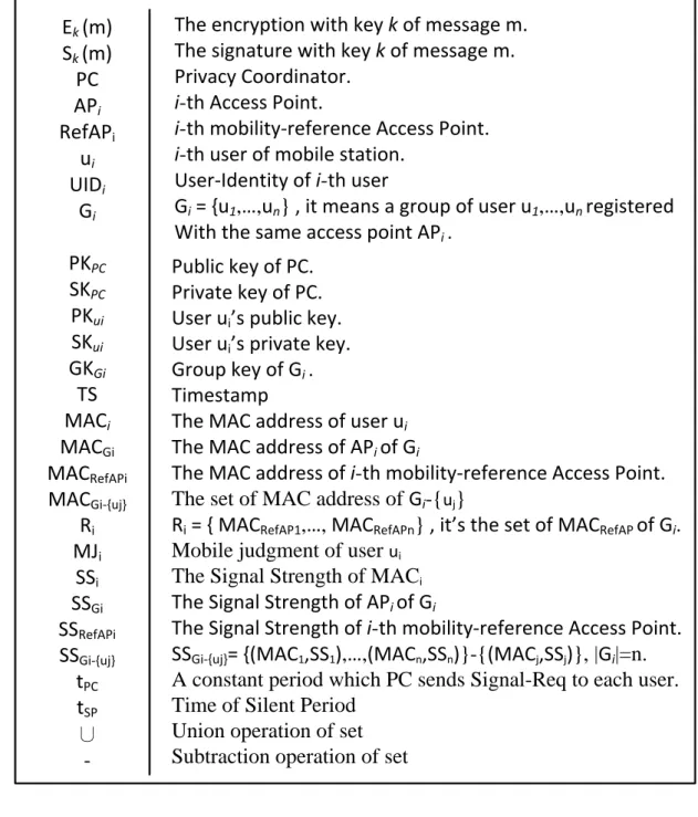
Table 3-1 Notations Ek (m) Sk (m) PC APi RefAPi ui UIDi Gi PKPC SKPC PKui SKui GKGi TS MACi MACGi MACRefAPi MACGi-{uj} Ri MJi SSi SSGi SSRefAPi SSGi-{uj} tPC tSP ∪
-The encryption with key k of message m. The signature with key k of message m. Privacy Coordinator.
i-th Access Point.
i-th mobility-reference Access Point. i-th user of mobile station.
User-Identity of i-th user
Gi = {u1,…,un} , it means a group of user u1,…,un registered With the same access point APi .
Public key of PC. Private key of PC. User ui’s public key.
User ui’s private key.
Group key of Gi . Timestamp
The MAC address of user ui The MAC address of APi of Gi
The MAC address of i-th mobility-reference Access Point. The set of MAC address of Gi-{uj}
Ri = { MACRefAP1,…, MACRefAPn} , it’s the set of MACRefAP of Gi.
Mobile judgment of user ui
The Signal Strength of MACi
The Signal Strength of APi of Gi
The Signal Strength of i-th mobility-reference Access Point.
SSGi-{uj}= {(MAC1,SS1),…,(MACn,SSn)}-{(MACj,SSj)}, |Gi|=n.
A constant period which PC sends Signal-Req to each user. Time of Silent Period
Union operation of set Subtraction operation of set
16
3.3 System Architecture
In the section, we will give an overview of our proposed scheme (Figure 3-2).
Introduce how the performing process of our system is, and detail complicated parts
in section 3.4. Before starting to describe our system, we define some notations in
Table 3-1 to help describe clearly. On the whole, the main idea of our proposed
scheme is letting the MS (uj) which associates with APi to collect the signal strength
of others ({APi} ∪ Gi - { uj }) , and then periodically send to PC for determining
which stations need to update their MAC address.
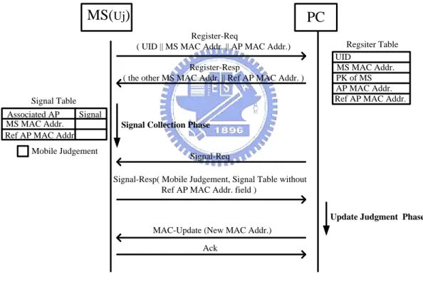
PC
MS(Uj)
UID MS MAC Addr. PK of MS Regsiter Table AP MAC Addr. Register-Req( UID || MS MAC Addr. || AP MAC Addr.) Register-Resp
( the other MS MAC Addr. || Ref AP MAC Addr. )
Ref AP MAC Addr. Signal Collection Phase
MS MAC Addr. Signal Table
Ref AP MAC Addr. Signal
Mobile Judgement
Signal-Req
Signal-Resp( Mobile Judgement, Signal Table without Ref AP MAC Addr. field )
Update Judgment Phase MAC-Update (New MAC Addr.)
Ack Associated AP
Figure 3-2 the overview of scheme
We assume that the PC has a public/private key pair (PKPC, SKPC), and each user (uj)
also has a public/private key pair (PKuj, SKuj). Therefore, when uj who associated with
APi wants his location privacy to be protected by the PC, uj will send a Register-
Request message to PC as follows.
17
Register-Request message mainly contains user identity of uj, the MAC address of uj,
and the MAC address of AP which uj currently associates with. When the PC receives
the message, it will verify the signature and timestamp. If both of them are valid, the
PC will add uj into Gi in Register Table. Basically, Register table is used to manage
group information. The group information contains group name (i.e. MACGi), all
user’s identities in the group, the current MAC address of user and the set of RefAP
MAC address (Ri).
Next, the PC sends the Register-Response message to uj and it also sends Table-
Update message to all the other users in Gi. We list the two kinds of message as
follows.
Register-Resp [ EPKuj (MACGi-{uj}||Ri ||GKGi||TS||SSKPC ( MACGi-{uj}||Ri ||GKGi ||TS)) ]
Table-Update [EGKGi (add||MACj||TS||SSKPC (add||MACj||TS))]
Therefore, uj will collect the signal strength of the nodes including Gi - {uj}, MACGi and
Ri (if they exists). In other words, uj enters the Signal-Collection Phase (discuss in
section 3.4.1). Each user continues collecting the signal strength in Signal-Collection
Phase until receiving the Signal-Request message. In every constant period tPC, the PC
sends Signal- Request to each user of Gi. After receiving the Signal-Request message,
each user uj sends the Signal-Response message to the PC. Basically, the Signal-
Response message includes the mobile judgment of uj (MJj), the signal strength of
MACGi and the signal strength of MAC Gi-{uj}.
Signal-Req [EGKGi(MAC Gi||TS|| SSKPC ( MACGi||TS)) ]
Signal-Resp [ EPKPC (MJj ||(MAC Gi,SS Gi)||SSGi-{uj}||TS||
18
After receiving the Signal-Response message, the PC will enter Update-Judgment
Phase (discuss in section 3.4.2) to determine those users who need to update their
MAC address. After completing Update-Judgment Phase, the PC sends MAC-Update
message to those users who need to update.
MAC-Update [EPKuj (new MACj||TS||SSKPC (new MACj||TS))]
Then, those users will send ACK to the PC, update their MAC address, and stop
sending frames for silent period tsp. Next, each user uj enters Signal-Collection Phase
to start another cycle again until leaving Gi. In addition, there are two methods to
know whether uj leaves Gi. One is uj actively send Leave message to the PC. Another
is the PC doesn’t receive the Signal- Response from uj. No matter which one, the PC
will send the following Table-Update message to the remainder (Gi - {uj}), and update
their group key to new one (GKGi′ ).
Leave [EPKPC(MACj||MACGi||TS||SSKuj(MACj|| MACGi|| TS))]
Table-Update [EGKGi (delete||MACj|| 𝐆𝐊𝐆𝐢′ ||TS||SSKPC (delete||MACj||𝐆𝐊𝐆𝐢′ ||TS))]
3.4 Detailing the Complicated Phase
In this section, we will describe the details of Signal Collection Phase (section 3.4.1)
and Update Judgment Phase (section 3.4.2).
3.4.1 Signal Collection Phase
In Signal Collection Phase, each user (uj) belongs to Gi has to complete two things.
One is collecting the signal strength of the nodes including Gi-{uj}, MACGi and Ri (if
they exists) .In our scheme, we let uj to maintain a table, called Signal-Table, to
19
when uj receives the Signal-Req request, it will calculate the mean of signal strength
for Gi-{uj} and MACGi. Then, uj will package the signal strength in the following format,
(MAC address, Signal Strength), for later transmission of Signal-Resp message.
Another is judging uj itself whether mobile or not in the period tPC between
receiving previous and current Signal-Req message. In our scheme, we use a number
of RefAPs (Ri) to help us achieve this judgment. The main idea of mobile judgment is
derived from pattern-based WLAN localization technique [6]. The pattern-based
WLAN localization technique utilizes station at different locations to sample the
signal strength of different AP. By this sample data, a mobile station can estimate its
location. Therefore, we use similar idea to determine whether uj doesn’t move in the
period tPC. We define a threshold, S, for RefAP. In addition, SS_Mean_tPC’_RefAPi
represents the mean of signal strength of i-th RefAP at previous period tPC’ . When uj
gets new SSRefAPi, the following operation will be done.
If | new SSRefAPi − SS_Mean_tPC’_RefAPi | > S
MJj <- Movable
In other words, Mjj will be set to Immobile only when every result of “| new SSRefAPi
− SS_Mean_tPC’_RefAPi | “ is small or equal to S in current period tPC.
After completing this phase, uj will tell the PC about the Mobile Judgment and the
MAC address/Signal Strength pair of Gi-{uj} and MACGi by sending the Signal-Resp
message.
3.4.1 Update Judgment Phase
20
their MAC address through the following two steps: calculation of relative coordinate
(section 3.4.2-1), judgment of mobile behavior (section 3.4.2-2).
3.4.2-1 Calculation of Relative Coordinate
Before calculating the relative coordinate for each node, the PC has to translate
the signal strength into distance. For different environment concerns, many
distance-dependent path loss models have been proposed [7, 8]. Therefore, we omit
this part, and detail the method of relative positioning directly.
We define dij to represent the estimated distance between ui and uj, and diG
represents the estimated distance between ui and associated AP. After the PC
receives the Signal-Resp message, the distance of each node can be estimated, i.e.
we can get the following Distance Matrix (DM) with size n x (n+1).
u
1u
2u
3… u
n MACGiu
1u
2u
3 . . .u
nd
11d
12d
13… d
1nd
1Gd
21d
22d
23… d
2nd
2Gd
31d
32d
33… d
3nd
3G . . . . . . . . . . . . . . .d
n1d
n2d
n3… d
nnd
nGDM =
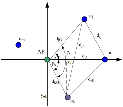
. . .Next, we use the relative positioning algorithm similar to Capkun’s [4], and
describe the algorithm briefly. Consider the scenario in which a group of n users
Gi = {u1, u2, …, un} registered with the same APi cooperate with the PC. In Addition,
21 APi ui uj uk djG diG dij dik djk um dkG α βk γk yuk xuk
Figure 3-3 An example for illustrating the relative positioning algorithm
The first step of our relative positioning algorithm is setting the coordinate of
the APi to origin (0, 0). Then we choose two nodes ui, uj ∈ Gi such that dij larger than
zero. Next, we place the coordinate of ui on the positive x-axis through referring to
the Distance Matrix, so the coordinate of ui is (diG, 0). In addition, calculate the angel
α and the coordinate of uj by the following operation:
(xuj, yuj) = diG cos α , diG sin α , where α = cos−1
djG2 + diG2 − dij2 2djGdiG
Thus, we have already known three different coordinates, and then we will use the
three known coordinates to determine the coordinate (xuk, yuk) of uk, where uk ≠ ui,
uj. Next, we use the following operation to calculate the coordinate of uk:
xuk = dkG cos βk if γk = βk− α then yuk = dkG sin βk else yuk = −dkG sin βk where, βk = cos−1 dkG 2 +d iG 2 −d ik 2 2dkGdiG and γk = cos −1 djG2 +dkG2 −djk2 2djGdkG .
22
Therefore, we can use the method mentioned above to calculate the remainder in Gi.
After the steps of calculation of relative coordinate, we will utilize this information to
judge the mobile behavior of each user and determine which users will change their
MAC address.
3.4.2-2 Judgment of mobile behavior
In this step, we mainly utilize the information of previous step to find out which users may be ambiguous for the attacker. In other words, we want to take our view
similar to the attacker’s as possible as we could. Therefore, toward increasing the
possibility of unlinkable MAC address and decreasing the possibility of useless
update is our goal. Basically, we divide this step into three cases to analyze the
mobile behavior of each user. One is Close-Enough case. Another is Mobile-Immobile
case which analyzes two users with different mobile behavior, i.e. one is mobile, and
another is immobile. The final case is Mobile-Mobile case which analyzes that two
users are both in mobile status. In our scheme, if the PC can’t provide any Ref AP for
the users or the number of immobile users is smaller than two in current Signal-Resp
message, we just have the ability to complete the Close-Enough case. Next, we
define a variable, updatei, which is a MAC-address-update flag for ui, and initialize it
as false for each user before beginning the following cases. And we detail each case
as follows.
i. Close-Enough case
In this case, we mainly analyze which users are close enough. Basically, the
idea is derived from the possibility of error estimate for current positioning
system. Therefore, we define a variable, called CETi (Close Enough Threshold)
23
triangulation which you want to resist. Therefore, we use the following simple
operation to complete the analysis of Close-Enough Case.
1 for j from 1 to n
2 for k from 1 to n
3 if DMjk ≤ CETi and j ≠ k
4 then updatej <- true , updatek <- true
After Close-Enough case, we have marked those users with a close enough
neighbor. Next, the Mobile-Immobile and Mobile-Mobile case will be
executed, only if the current Signal-Resp message includes at least two
immobile users. The reason is judging a user’s mobile direction and velocity in
2D-plane. We need at least three immobile points to refer. Because the APi is
one of the three immobile nodes, we just need two immobile nodes more. In
addition, our scheme will record the previous (xuj′ , yuj′ ) and current coordinate (xuj, yuj) of each user uj for the judgment of the user’s mobile behavior. Finally,
if the current Signal-Resp message includes at least two immobile users, there
is a little bit different in our relative positioning algorithm. We will set the
current coordinate of immobile users equal to previous coordinate. Then the
PC utilizes these current coordinates of immobile nodes including APi to find
out the coordinates of the remainder by similar way in section 3.4.2-1.
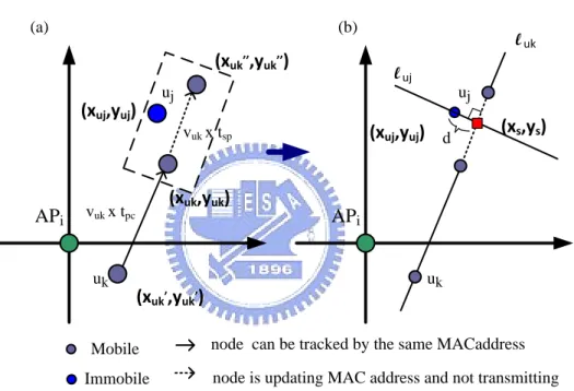
ii. Mobile-Immobile case
We utilize the previous (xui′ , yui′ ) and current coordinate (xui, yui) of each user ui to realize the mobile behavior about direction and velocity. Therefore,
24
Basically, this case mainly analyzes whether there is an immobile user uj close
enough to a mobile user uk’s future path (i.e. from (xuk, yuk) to (xuk′′, yuk’’))
in silent period tsp. If this situation holds, it is an opportune time to make the
attacker ambiguous. We use Figure 3-4 to help realize the analyzing process.
Figure 3-4 (a) is an example for illustrating the previous mention, and Figure
3-4 (b) illustrates how to know whether the close-enough situation holds or
not. APi uj (xuk,yuk) (xuk,,yuk,) (xuj,yuj) uk
node is updating MAC address and not transmitting node can be tracked by the same MACaddress Mobile Immobile APi uj (xuj,yuj) luk uk luj (a) (b) (xuk,,,yuk,,) vuk x tpc vuk x tsp d (xs,ys)
Figure 3-4 illustrating the Mobile-Immobile case
The gray node represents a mobile user uk, and the blue node represents a
immobile user uj. We divide the group Gi into two set, i.e. a mobile set and an
immobile set. For each user uk who belongs to the mobile set will do the
following operations for each user uj who belongs to the immobile set.
Step 1: Calculate the straight-line equation of l uk by previous coordinate
25
Step 2: Calculate the straight-line equation of l uj which is both orthogonal to
luk and passes the coordinate of the immobile user uj (xuj, yuj).
Step 3: Calculate the coordinate (xuk′′ , yuk′′ ) by (xuk′′ , yuk′′ ) = (xuk, yuk) + VVuk× tsp uk× tPC (xuk − xuk ′ , y uk − yuk′ ) , where vuk = (xuk−xuk′ )2+(yuk−yuk′ )2 tPC
Step 4: Calculate the coordinate (xs,ys) by solving the linear system of equation,
i.e. l uk and l uj.
Step 5: if the following two situations both hold, we will set true for updatej
and updatek.
Situation 1:
(xs,ys) is an element of the set which contains the solution set of the line
l uk between (xuk′′ , yuk′′ ) and (xuk, yuk).
Situation 2:
The distance d between (xuj, yuj) and the line l uk is small or equal to CETi
(Close Enough Threshold).
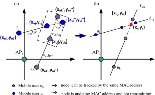
iii. Mobile-Mobile case
In the Mobile-Mobile case, we only discuss the case that both the two
users are in mobile status. Basically, this case mainly analyzes whether two
mobile users (uj,uk) will cross each other in the future path of silent period tsp.
If this situation holds, it is an opportune update-time to make the attacker
ambiguous. We use Figure 3-5 to explain the analyzing process. Figure 3-5 (a)
is an example for illustrating the previous mention, and Figure 3-5 (b)
26 APi uj (xuk,yuk) (xuk,,yuk,) (xuj,yuj) uk
node is updating MAC address and not transmitting node can be tracked by the same MACaddress Mobile user uk Mobile user uj APi uj (xuj,yuj) l uk uk l uj (a) (b) (xuk,,,yuk,,) vuktPC vuktsp (xs,ys) (xuj,,yuj,) (xuj,,,yuj,,) vuj tPC vuj tsp
Figure 3-5 illustrating the Mobile-Mobile case
The gray node and blue node respectively represent the mobile user uk and
uj. For each user uk who belongs to the mobile set will do the following
operations for each user uj who belongs to the mobile set.
Step 1: Calculate the straight-line equation of l uk by previous coordinate
(xuk′ , yuk′ ) and current coordinate (xuk, yuk) of the mobile user uk.
Step 2: Calculate the straight-line equation of l uj by previous coordinate
(xuj′ , yuj′ ) and current coordinate (xuj, yuj) of the mobile user uj.
Step 3: Calculate the coordinate (xuk′′ , yuk′′ ) by (xuk′′ , yuk′′ ) = (xuk, yuk) + VVuk× tsp uk× tPC (xuk − xuk ′ , y uk − yuk′ ) , where vuk = (xuk−xuk′ )2+(y uk−yuk′ )2 tPC
Step 4: Calculate the coordinate (xuj′′, yuj′′) by the method similar to Step3. Step 5: Calculate the coordinate (xs,ys) by solving the linear system of
27
Step 6: if either the following situation holds, we will set true for updatej and
updatek .
Situation 1: (xs,ys) is an element of the set which contains the solution
set of the line l uk between (xuk′′ , yuk′′ ) and (xuk, yuk) and (xs,ys) is also an
element of the set which contains the solution set of the line l uj between
(xuj′′, yuj′′) and (xuj, yuj).
Situation 2: the distance d between (xuk′′ , yuk′′ ) and (xuj′′, yuj′′) is small or
equal to CETi (Close Enough Threshold).
3.4.2 -3 Update MAC address
After completing the judgment of mobile behavior, we will choose a new MAC
address for the user uj whose updatej has been set to true. Then, we use a
Spatio-Temporal Addressing [9] to generate a new MAC address for avoiding collision.
Basically, the main idea of Spatio-Temporal Addressing is based on the fact that two
objects cannot exist at the same location at the same time. Therefore, we can
achieve this goal of avoiding collision through an injection function .Finally, we send
MAC-Update message to those users who need to update MAC address.
4. Evaluation
In this chapter, we mainly point out the improvement of our scheme on the two
factors, unlinkable MAC address and useless update. Therefore, we will compare our
proposed scheme with the prior arts [1, 2], and the remainder of this section is
28 analyze the simulation result in section 4.2.
4.1 Simulation Setup
Our simulation environment is a 60m*60m 2-dimentional grid-area, and all mobile
users move within this area by random walking model. The random walking model
defines the patterns of moving direction [←, ↑, →, ↓], the probability of moving
direction [p←, p↑, p→, p↓], velocity range [vmin, vmax] and the probability of changing
velocity [p+, pno, p-] (i.e. [speed up, unchanged, slow down]). In our simulation, we
set the parameters of random walking model as follows:
[p←, p↑, p→, p↓] = [0.15, 0.65, 0.15, 0.05]
[vmin, vmax] = [0 , 3] with unit (m/s)
[p+, pno, p-]= [0.1,0.8,0.1] with unit (1 m/s)
The values of these parameters take the mobile behavior of pedestrian into account.
In addition, in order to make our simulation analogous to real wireless propagation.
We actually measure the relation between signal strength and distance (1-meter
interval) for the wireless interface of the mobile station and AP in an obstacle-less
environment. We also log the signal-strength/distance information for later use.
Finally, we use a similar way [10] to obtain an empirical path loss model for both the
mobile station and AP. Hence, when a node (ui) wants to send a frame, all the other
nodes can obtain the signal strength by the log information. In other words, all the
other nodes will randomly choose a signal-strength value from the log information
according to the distance between ui and themselves. And then the PC translates the
signal strength to distance by the empirical path loss model.
Next, we describe the tracking model used by attackers. First, the attackers will
divide all the users into two type, target and disturber. Target is the user who the
29
track target. In addition, the attackers utilize the same empirical path loss model to
obtain the distance information, and track the targets by triangulation. Finally, when
a target uj update its MAC address and doesn’t transmit any frame for a random
period, the attackers will randomly pick an unobserved MAC address to track from
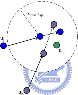
the circle area,( i.e. the center of circle is the missing point of uj, and the circle area is
tsp × vmax). We use Figure 4-1 to illustrate this situation. So the adversary will randomly pick from these users including uj, uk and um.
uj
uk
um
vmax tsp
node is updating MAC address and not transmitting node can be tracked by the same MACaddress
Figure 4-1 illustrating which users will be picked as target
4.2 Simulation Result and Analysis
Due to the prior works [1,2] analyzed the factor ,unlikable MAC address, through
measuring how long a node can be tracked continuously. Therefore, we will use
similar factor to evaluate the performance of our proposed scheme and realize the
30
Figure 4-2 CDF of tracking time
We show the simulation result of unlikable MAC address in Figure 4-2, which is
plotted as a cumulative distribution function. The curve indicates the percentage of
nodes (y-axis) that can be tracked for no more than a specified duration (x-axis). The
“Only Change MAC” curve indicates the system which only adopts disposable MAC
address scheme [1]. Next, the “change MAC with 2s silent period” means the system
will stop sending frames about 2 seconds after each update of MAC address [2].
Finally, the “My Scheme with 2s silent period” indicates the system adopts our
proposed scheme. Now, consider the fifth tracking round of x-axis. In our scheme,
there are only about 30% nodes can be tracked after the 5th tracking round. This
value is smaller than both the disposable scheme (70%) and silent-period scheme
(50%). Therefore, our scheme effectively reduces the duration of time that a user can
be tracked. 0 0.1 0.2 0.3 0.4 0.5 0.6 0.7 0.8 0.9 1 0 5 10 15 20 25 30
Only Change MAC
change MAC with 2s silent period My Scheme with 2s silent period
Tracking Round
Percentage o
31
Figure 4-3 Comparison of maximal tracking round
Next, we show the comparison of maximal tracking round for each scheme in
Figure 4-3. In our scheme the whole users can be traced at most 9 rounds. The value
is far smaller than 27 rounds of disposal scheme and also smaller than 14 rounds of
silent-period scheme. In other words, our scheme has the ability to obtain higher
location privacy within less time.
Figure 4-4 Comparison of useless MAC address update
Finally, we analyze the improvement of useless MAC address update in Figure 4-4.
Figure 4-4(a) shows that we conserve 67% useless MAC address updates as
compared our scheme with disposable scheme. In addition, compared with silent
period scheme we also conserve about 35% useless MAC address updates (Figure 4-4 0 5 10 15 20 25 30
Only Change MAC change MAC with 2s silent period My scheme with 2s silent period Tracking R o und 67% Useless MAC address Updates 33% 35% Useless MAC address Updates 65%
32
(b)). This result substantially reduces the number of useless update and improves the
performance of each user.
5. Conclusion.
In this thesis, we first described the problem of prior works without considering
the mobile behavior of neighboring nodes. Furthermore, we pointed out that the
drawbacks mainly derived from not taking mobile behavior into account, i.e. useless
update and missing the opportune moment to update. So we proposed a new
scheme to enhance location privacy through relative positioning system and the
analysis of mobile behavior. By the experiment result, the duration of time that the
whole users can be tracked respectively reduces to one-third and nine-fourteens as
compared with prior works. In addition, our scheme also respectively conserves 67%
and 35% useless MAC address updates as compared with prior works. Therefore, our
scheme obviously has the ability to enhance effectively the user’s location privacy
33
References
[1] M. GRUTESER and D. GRUNWALD,“Enhancing location privacy in wireless LAN
through disposable interface identifiers: a quantitative analysis,” in Proceedings
of 1st ACM international workshop on Wireless mobile applications and services
on WLAN hotspots (WMASH 2003), 2003 and Mobile Networks and Applications,
2005.
[2] L. Huang, K. Matsuura, H. Yamane, and K. Sezaki, “Enhancing wireless location
privacy using silent period,” in Proceedings IEEE Wireless Commun. Netw.
Conf. ,2005.
[3] K. E. Defrawy, C. Soriente, “PEUC-WiN: Privacy Enhancement by User Cooperation
in Wireless Networks,” in Secure Network Protocols 2nd IEEE Workshop,
November 2006.
[4] S. Capkun, M. Hamdi, and J. Hubaux, “GPS-free positioning in mobile ad-hoc
networks,” in HICSS ’01: Proceedings of the 34th Annual Hawaii International
Conference on System Sciences (HICSS-34)-Volume 9. Washington, DC, USA: IEEE
Computer Society, 2001.
[5] M. Li, K. Sampigethaya, L. Huang and R. Poovendran, “Anonymity: Swing & swap:
user-centric approaches towards maximizing location privacy,” in Proceedings of
the 5th ACM workshop on Privacy in electronic society WPES '06, October 2006.
[6] P. Bahl and V. Padmanabhan, “RADAR: An in-building RF-based user location and
tracking system,” in Proceedings of IEEE INFOCOM, 2000.
[7] S. Phaiboon, “An empirically based path loss model for indoor wireless channels
in laboratory building,” in Proceedings of TENCON’02, 2002.
34
Bianchi, “ An empirically based path loss model for wireless channels in suburban
environments,” IEEE Journal on Selected Areas in Communications, 1999.
[9] K. Yamazaki and K. Sezaki,“Spatio-temporal addressing scheme for mobile ad hoc
networks,” in Proceedings of IEEE TENCON, 2004.
[10] Seong H. L., Kwang W. N. and Kwang S. K., ”The Location-based Services in Local
Area using Wireless LAN”.
[11] A. Juels, R. L. Rivest and M. Szydlo, “The Blocker Tag: Selective Blocking of RFID
Tags for Consumer Privacy,” In Proceedings of 10th ACM Conference on
Computer and Communications Security (CCS’03), October 2003.
[12] Bluetooth 1.2 Draft 4, Bluetooth SIG Standard, 2003.
[13] A. R. Beresford and F. Stajano “Location Privacy in Ubiquitous Computing,”
Published by the IEEE CS and IEEE Communication Society, 2003.
[14] A. Gorlach, A. Heinemann and W. W. Terpstra, “Survey on Location Privacy in
Pervasive Computing.”
[15] D. Fox, “Der IMSI-Catcher,” Datenschutz und Datensicherheit 26 (in German),
2002.
[16] M. Gruteser and D. Grunwald, “A methodological assessment of location privacy
risks in wireless hotspot networks,” in Proceedings of 1st Intl. Conf. on Security
in Pervasive Computing (SPC 2003), ser. LNCS, vol. 2802, Boppard, Germany:
Springer, 2003.
[17] H. Kido, Y. Yanagisawa and T. Satoh, “Protection of Location Privacy using
Dummies for Location-based Services,” in Proceedings of the 21st International Conference on Data Engineering (ICDE’05), 2005.
[18] A. Kushki, K. N. Plataniotis and A. N. Venetsanopoulos, “Location Tracking in
Wireless Local Area Networks with Adaptive Radio Maps,” IEEE ICASSP, 2006.
35
International Conference on Communications, 1995.
[20] B. Schilit, J. Hong and M. Gruteser, ”Wireless Location Privacy Protection,” in
IEEE Computer Society, 2003.
[21] M. Gruteser and D. Grunwald, “Anonymous Usage of Location-Based Services
Through Spatial and Temporal Cloaking,” in Proceedings of the 1st international
conference on Mobile systems, applications and services MobiSys '03, May
2003.
[22] C. L. Bowen and T. L. Martin, “A Survey of Location Privacy and an Approach for
Solitary Users, ” in Proceedings of the 40th Annual Hawaii International Conference on System Sciences (HICSS’07), 2007.
[23] Y. C. Hu and H. J. Wang, “A Framework for Location Privacy in Wireless