IRIS App:互動式2.0手機廣播電台應用程式 - 政大學術集成
51
0
0
全文
(2) I IRIS App:互動式 2.0 手機廣播電台應用程式 IRIS App: Interactive 2.0 Radio System on the Internet over Smartphone 研 究 生:林凱禎. Student:Kai-Chen Lin. 指導教授:蔡子傑. Advisor:Tzu-Chieh Tsai. 國立政治大學 資訊科學系 碩士論文. A Thesis submitted to Department of Computer Science National Chengchi University in partial fulfillment of the Requirements for the degree of Master in Computer Science. 中華民國一百零二年一月 Jan 2013 2.
(3) IRIS App:互動式 2.0 手機廣播電台應用程式. 摘要. 智慧型手機的功能日漸強大,而我們希望能夠利用智慧型手機普及的趨勢,實作一 個能夠讓眾人互動的電台應用程式,IRIS:互動式2.0手機廣播電台應用程式。聽眾能夠 透過網路與在廣播電台上建立節目的分享者連線,來收聽分享者目前正在播放的音樂歌 曲。在此,我們將分享者稱作是“網路DJ”,聽眾可以透過頻道來選擇喜歡的電台。而原 本僅能收聽音樂的使用者則可以隨時選擇成為“網路DJ”,並且經營屬於自己風格的網路 電台。 “網路DJ”除了單純分享音樂外,也可以透過手機上的麥克風收音來主持節目。如果 聽眾對“網路DJ”有任何回應,還可以使用Call-in進行網路電話型式的網路對談。 然而因為手機本身有網路傳輸的問題。手機上網時通常位在網路交換器背後,因為 使用虛擬位址以至於彼此之間無法直接進行連線。並且當系統內有多名“網路 DJ”同時進 行放送時,將會有多條不同的聲音串流來爭奪伺服器網路的頻寬,並且造成提供服務的 伺服器負擔。為了解決這些問題,我們要優先處理無法直接連線的困境,接著並引入了 簡單的負載平衡方式來分散聽眾,進而解決伺服器網路的瓶頸。最後,我們作出這個廣 播電台應用程式並且有令人滿意的運行結果。. 關鍵字: 手機應用程式、廣播電台、網路電話、網路位址交換、負載平衡系統.
(4) IRIS App: Interactive 2.0 Radio System on the Internet over Smartphone Abstract. Smartphones are more powerful and popular nowadays. We hope to utilize smartphones to develop an interactive radio application, IRIS: Interactive 2.0 Radio System on the Internet over Smartphone. Using this App, a user can create a channel and become a “DJ” to provide the show. Otherwise, he/she can be the audience to choose the radio channel that his/her favorite DJ hosts. The DJ not only provides the music but also can anchor by the microphone on the smartphone. If the audience has any feedback to the DJ, he/she can make a call-in to talk interactively with DJ by the VoIP service. To this end, there is a problem on network transmission over smartphone. Because smartphones are usually behind NAT, it would cause no one to be able to connect to each other directly due to private IPs. Besides, when many DJ provide their shows on the air, it might cause many streaming relays to overload the Server. Therefore, we need to solve the NAT problem and alleviate the loading on the server by deploying a load balancing architecture. The App and the radio system were developed and the results were satisfactory.. Keywords: Smartphone App, Radio, VoIP, NAT, load balance. ii.
(5) 致謝辭 研究生的生活轉眼間要結束了,感謝許多人對我的關心與厚愛,讓我得以完成這份 論文。首先,我要感謝我的指導教授,蔡子傑老師。感謝老師不厭其煩的引導與建言, 在過去的日子裡,我的研究進度時常遭逢難題而停滯不前,老師總是毫不介意並且不吝 惜自己的時間抽空開導我,讓我最後都能安然度過難關。同時也要感謝百忙中抽空前來 的口試委員:吳曉光教授、周承復教授、林宗男教授、陳伶志教授,感謝親切的口試委 員們,讓我度過一場愉快的口試,同時也給予我許多寶貴的意見,讓我針對不足的部分 加以改善。 感謝一直包容和照顧我的學長姐們。謝謝東諺學長與惠翔,兩位留下的程式讓我接 手使得我的論文得以繼續開發延伸。謝謝文卿學姐、育晟、勇麟、界誠、泰榮學長親切 又熱心的照顧,讓我學習了不少寶貴的經驗,在我做錯事情的時候,及時出手支援幫助 我導正錯誤,也特別謝謝勇麟學長,在我深夜困在台北車站的時候,二話不說立即從中 永和開車來載我回政大。謝謝我的同屆,一起奮鬥的夥伴們,偉敦、彥嵩、思采、信慈, 謝謝你們的陪伴,讓我的研究生生涯過的精彩亮麗多采多姿。謝謝和我一同口試的英明, 提點了許多我沒注意的細節。謝謝學弟妹,欣諦、昶瑞、煜泓、宇軒、建淳、凱柔、筱 璇、聖傑和賀翔,沒能提供你們什麼特別的幫助感到很抱歉,謝謝你們的體諒。謝謝所 有我認識的資科和數位內容的學長姐同學學弟妹以及我的朋友們,祝你們事事順心,一 切順利。 最後,我要感謝我最愛的家人以及身旁的親戚朋友,無時無刻都給予我最大無私的 支持鼓勵與包容,不斷地為我加油打氣,因為有你們的關心與幫助,我才能熬過這艱苦 的逆境,對此我心中有著無比的感激,僅以字句聊表心意,謝謝你們。 再次感謝以上所有人,謝謝你們在我的生命中都添上了一筆,感激不盡。. iii.
(6) TABLE OF CONTENTS. CHAPTER 1.................................................................................. 1. 1.1 Background ............................................................................................. 1 1.1.1 The Network Address Translation (NAT) ............................... 1 1.1.2 The Load Balancing System .................................................... 2 1.2 Motivation for IRIS................................................................................ 3 1.3 Organization ........................................................................................... 6. CHAPTER 2.................................................................................. 7. 2.1 Network Address Translation ............................................................... 7 2.2 Network Address Translation Traversal .............................................. 9 2.3 Load balancing System ........................................................................ 13. CHAPTER 3 .................................................................................. 15. 3.1 IRIS Architecture ................................................................................. 15 3.2 IRIS Construction ................................................................................ 18 3.2.1 DJ Join................................................................................................ 18 3.2.2 Audience Join .........................................................................20 3.2.3 Call-in .....................................................................................21 3.2.4 Load Balancing Server Relay .................................................22. CHAPTER 4 .................................................................................. 25. 4.1 Reality .................................................................................................... 25 iv.
(7) 4.2 Traversal Using Relay NAT ................................................................ 26 4.3 Load Balancing System........................................................................ 28 4.3.1 IRIS without Load Balancing .................................................28 4.3.2 Secondary Server Load Balancing .........................................28 4.3.3 Three DJ in IRIS ....................................................................30 4.3.4 Call-in In IRIS ........................................................................31 4.4 User Interface ....................................................................................... 32 4.4.1 Audience .................................................................................34 4.4.2 DJ............................................................................................37. CHAPTER 5 .................................................................................. 39. Reference ........................................................................................ 40. v.
(8) LIST OF FIGURE Figure 1 The Internet over smart phones ............................................... 2 Figure 2 Traditional Radio System ........................................................ 4 Figure 3 Skype Communication ............................................................ 5 Figure 4 The Network Address Translation ........................................... 8 Figure 5 Flowchart of Simple Traversal of UDP through NATs algorithm ...................................................................................... 12 Figure 6 The load balancing system. ................................................... 14 Figure 7-1 A load balancing IRIS architecture .................................... 15 Figure 7-2 IRIS architecture with Firewall .......................................... 17 Figure 8 Simple construction of IRIS .................................................. 18 Figure 9 Flowchart of DJ Join ............................................................. 19 Figure 10 Flowchart of Audience Join ................................................ 20 Figure 11 Flowchart of Call-in service ................................................ 22 Figure 12 Flowchart of Secondary Server service ............................... 23 Figure 13 The implement devices ....................................................... 25 Figure 14 NAT traversal ...................................................................... 27 Figure 15 IRIS without Load Balancing .............................................. 28 Figure 16 IRIS works load balancing with Secondary Server . ............ 29 Figure 17 Three DJ are on the air in IRIS............................................ 31 Figure 18 A audience make a call-in to DJ. ......................................... 32 Figure 19 Flow chart of IRIS .............................................................. 33 vi.
(9) Figure 20 Login interface .................................................................... 34 Figure 21 Audience interface .............................................................. 35 Figure 22 DJ interface ......................................................................... 37. vii.
(10) LIST OF TABLE Table 1 The comparison of applications ..................................... 6 Table 2 The traversal technology of NAT problems................. 12 Table 3 Experimental Setup ..................................................... 26. ii.
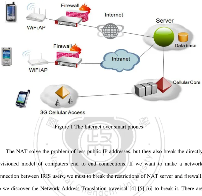
(11) CHAPTER 1 Introduction. 1.1 Background. 1.1.1 The Network Address Translation (NAT) [1] [2] The Network Address Translation is a computer network technology to help extend the life of IPv4 address before IPv6 address protocol is deployed. This technology admits a small number of public IP addresses to be shared by a large number of hosts using private addresses [3]. In IRIS, or in other words, most of smart phone were built by using Wi-Fi or 3G network technology to transfer data to the Internet. The Wi-Fi would connect through the wireless access point (AP), and the 3G network would connect to 3G Cellular Access. They are both applications for the NAT utilization. The Fig 1-1 depicts the construction of the network connection over smart phones.. 1.
(12) Figure 1 The Internet over smart phones. The NAT solve the problem of less public IP addresses, but they also break the directly envisioned model of computers end to end connections. If we want to make a network connection between IRIS users, we must to break the restrictions of NAT server and firewall. So we discover the Network Address Translation traversal [4] [5] [6] to break it. There are few NAT traversal protocols and techniques based on NAT behavior. We will discuss them in next chapter and then finding out a solution to traverse the problem.. 1.1.2 The Load Balancing System [7] [8] [9]. The load balancing system is built to balancing the Internet traffic just the meaning in the word. In common sense, there are many network applications and protocols like web service,. 2.
(13) email, VoIP, etc. that caused the Server accepted multiple network connection. For example, the web services, when browsers connect to the Internet, they commonly open multiple requests, one for the text, another for an image, another for some other image, sometimes another for music streaming. To avoid the server was overloading by too much services, it commonly provide extremely servers or devices so that ease of the loading pressure of the primary server. Among our radio system would request and produce much music streaming by many users in most of time, it need excessively to implement the load balancing architecture into our system. The streaming data were raw data that sends and receives between nodes in our system. There are many codec like mp3, 3gp, amr to encode the raw streaming. But in Android API is not supported in streaming play with that formats except raw data like pcm. If we encoded the raw data into mp3 for transmission, there were needed to decode the mp3 back to the raw data before the streaming play. And the smart phone CPU rate and cache are usually lower than PC or notebook; the encoder and decoder must consume most of CPU rates and stop other thread progresses, which is a big problem in real time system. In business, Skype, Line, MSN have their codec for streaming. It needs treasury to buy the authorization for codec or we develop our own. In this case, we choose transfer raw data streaming successfully to construct the system first before using codec to encode streaming. The codec for compression will construct in our future work.. 1.2 Motivation for IRIS. The function of the intelligent cell-phone, or which is called smart phone, is strong day by day, 3.
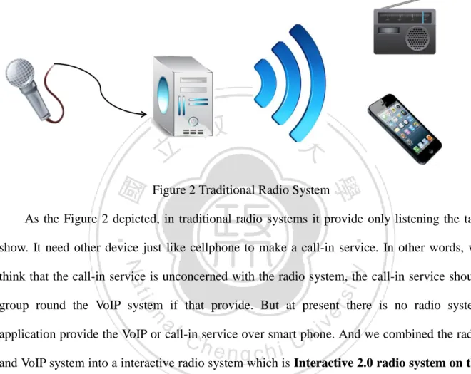
(14) and that we hope to utilize the popular trend of the smart phone, implement a system which shares the Internet radio for music listening as the foundation with the user. The audiences could choose the channel of the DJ they like to listen to the radio through the network.. Figure 2 Traditional Radio System As the Figure 2 depicted, in traditional radio systems it provide only listening the talk show. It need other device just like cellphone to make a call-in service. In other words, we think that the call-in service is unconcerned with the radio system, the call-in service should group round the VoIP system if that provide. But at present there is no radio system application provide the VoIP or call-in service over smart phone. And we combined the radio and VoIP system into a interactive radio system which is Interactive 2.0 radio system on the Internet over smart phone, and we named it IRIS for short. The common uses were just like the other Internet radio application on smart phones, TuneIn Radio [10], Pandora [11], etc...The first two are both much famous applications in iOS and Android system. But they only provide the audience function for users, and audiences could not talk interactively to the DJ. In IRIS, we provide two unique services. The first is a DJ service. When audience could not find the favorite DJ talk shows, or compare to listening he would like to be a DJ to play and share music with others, now he has a choice to become 4.
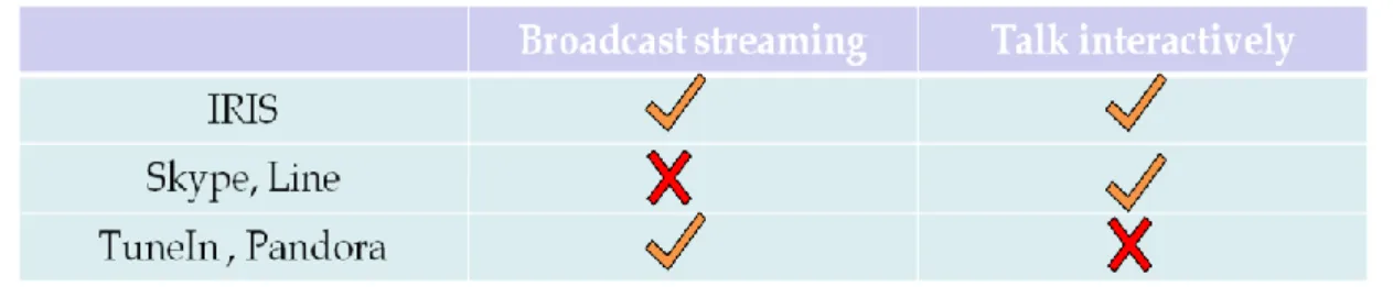
(15) the role he like.. Figure 3 Skype Communication. The second service is call-in. When audience is listening to the music streaming from DJ, he could make a call-in to DJ anytime. After DJ accepted his request, they talk to each other like VoIP service for interactive. Another VoIP services for instance, Skype [12] [13] and Line [14], that both support VoIP services over smart phone. But in their two systems only support one to one audio communication nowadays. Figure 3 represent the situation of Skype communication. They could not broadcast the audio streaming. Even if extend the all functions from PC in the future. All users in both systems are invited into talk and not be the audience only. The following Table 1 depicts the comparison of applications we discussed in this chapter.. 5.
(16) Table 1 The comparison of applications. 1.3 Organization. The rest of this thesis is organized as follows. Chapter 2 introduces related works in Load Balancing IRIS. In Chapter 3, we present our system architecture and the flowchart of IRIS. Chapter 4 describes the implementation of IRIS and the network development. Chapter 5 concludes the thesis and remarks on future work.. 6.
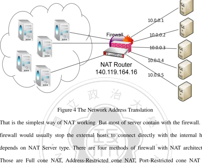
(17) CHAPTER 2 Related Work. 2.1 Network Address Translation. The Network Address Translation is a computer network technology to help extend the life of IPv4 address before IPv6 address protocol is deployed. This technology admits a small number of public IP addresses to be shared by a large number of hosts using private addresses [3]. The Figure 4 depicts the operation of Network Address Translation. When the computer is behind the NAT server transfer a packet to the Internet, which is used Private IP Address. The NAT server would transform the Private IP Address to a relative Public IP address. For example, transforming the IP address from 10.0.0.1 to 140.119.164.16. If NAT server receives a packet from the Internet, the server will find out the destination of the packet, and then transform the Public IP Address to a relative Private IP address.. 7.
(18) Figure 4 The Network Address Translation That is the simplest way of NAT working. But most of server contain with the firewall. The firewall would usually stop the external hosts to connect directly with the internal hosts depends on NAT Server type. There are four methods of firewall with NAT architecture. Those are Full cone NAT, Address-Restricted cone NAT, Port-Restricted cone NAT and Symmetric NAT. Full cone NAT is the simplest method of NAT, and does not need to traverse. An internal address and port (iAddr: iPort) is mapped to a constant external address and port (eAddr: ePort). Any external host could connect to (iAddr: iPort) by sending packets to (eAddr: ePort). The method of Address-Restricted cone NAT, once an internal address (iAddr: iPort) is mapped to a constant external address (eAddr: ePort), any packets from iAddr: iPort will be sent through eAddr: ePort. And an external host (hAddr: any port) can send packets to iAddr: iPort by sending packets to eAddr: ePort only if iAddr: iPort has previously sent a packet to hAddr. Port-Restricted cone NAT is just like an Address Restricted cone NAT, but the restriction 8.
(19) includes port numbers. An internal address (iAddr: iPort) is mapped to a constant external address (eAddr: ePort). An external host (Haddr: Hport) can send packets to iAddr: iPort by sending packets to eAddr: ePort only if iAddr: iPort has previously sent a packet to Haddr: Hport. Symmetric NAT is the most complex one. Each request from the same internal IP address and port to a specific destination IP address and port will be mapped to a unique external IP address and port, if the same internal host sends a packet even with the same source address and port but to a different destination, it is mapping to the totally different IP address and port. And only if an external host that receives a packet from an internal host can send packets back.. 2.2 Network Address Translation Traversal. The NAT protocols were developed to solve the problem of less public IP addresses, but they break the directly envisioned model of computers end to end connections. So there are more traversed solutions developing to take cover the new problem. Before we find a way out to traverse to NAT, we have to find what the method of the NAT took, that is just common sense. We will discuss three methods of NAT traversal. Session Traversal Utilities for NAT is called STUN [15] for short, Traversal Using Relay NAT (TURN) [16] [17] [18], Interactive connectivity Establishment (ICE) [19]. Figure 5 depicts the flowchart of Simple Traversal of User Datagram Protocol (UDP) through Network Address Translators (NATs) algorithm [20]. Simple Traversal of UDP through NATs is a standardized for dealing with NAT. It help client to ascertain NAT behavior but is not a self-contained solution. Therefore Simple 9.
(20) Traversal of UDP through NATs server must be with the help of the others. In Test I, the internal host sends a change-request to Simple Traversal of UDP through NATs server. This causes the server to send the response back to the host that the request came from. In Test II, the internal host sends a binding-request with different address and different port. In Test III, the host sends a binding-request with the same address and different port. In the beginning by initiating Test I, if this test yields no response, which means that is no capability of UDP connection. If the test yields a response, the host will examine the mapping attribute. Now that is two position to continue, the first position if the host using the same external IP address and port as the local IP address and port to send the request, the host realize there is no natted. And then it execute test II. If the host receives a response, which means the host has open access to the Internet. If there is no response, which means the host is behind a Symmetric NAT. The second position that the IP address and port did not match the mapping attributes, which means the host is behind a NAT. Then it executes Test II. If the host receives a response, the host knows it is behind a Full-Cone NAT. If there is no response, it executes Test I again. If the response of Test I is not the same IP address and port as the ones from the first time Test I result, the host is behind a Symmetric NAT. Or else, the response is the same IP address and port as the first time result, then executing Test III. If a response is received, the host is behind an Address-Restricted NAT, and if no response is received, it is behind a Port-Restricted NAT.. 10.
(21) 11.
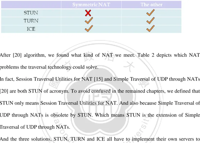
(22) Figure 5 flowchart of Simple Traversal of UDP through NATs algorithm. Table 2 The traversal technology of NAT problems. After [20] algorithm, we found what kind of NAT we meet. Table 2 depicts which NAT problems the traversal technology could solve. In fact, Session Traversal Utilities for NAT [15] and Simple Traversal of UDP through NATs [20] are both STUN of acronym. To avoid confused in the remained chapters, we defined that STUN only means Session Traversal Utilities for NAT. And also because Simple Traversal of UDP through NATs is obsolete by STUN. Which means STUN is the extension of Simple Traversal of UDP through NATs. And the three solutions, STUN, TURN and ICE all have to implement their own servers to traverse the problems. STUN server is allocated public IP address, and doesn’t work on symmetric NAT. STUN server only help to trace the external address to internal host, and because of symmetric NAT is mapping by source IP address, source IP port, destination IP address and destination port. So after executing the algorithm, the system doesn’t work if the type of NAT is a Symmetric NAT. Traversal Using Relay NAT (TURN) [16] is Client-Server architecture. It is similar to STUN, which both need servers to search a real path or external public address to the client behind NAT for connections. When client needs to traverse the NAT receiving some thing before,. 12.
(23) client must to make a connection with TURN server. First, the client user send a allocate request to TURN server. The request asks server to allocate the client with an “allocated relayed transport address”. So that the other users could send a packet to the client behind NAT by using the allocated relayed transport address. In other words, if someone wants to connect with the client, it can send the packets to the TURN server, and then TURN server will use the “allocated relayed transport address” to relay the packets to the destination. In distinctness, STUN server trace the NAT type, and find the way to connect directly. After STUN server traversed the NAT, it gave a link to the host; the host uses the link to connect others by point-to-point. TURN server gave a relay address. Everyone has to send a packet to client through TURN server. Therefore, TURN server will be the bottleneck in the future connections. But TURN is a much useful way to traverse the NAT, because it could handle all the types of NAT, include Symmetric NAT. Interactive Connectivity Establishment (ICE) [19] is combination technology of NAT traversal. In other word, it combines the other NAT traversal algorithm into its. It is commonly the combination of TURN and STUN, or you could combine the other NAT traversals for yourself. First, ICE executed the algorithm of STUN. STUN finds the type of NAT in front of the host, and then traverses the problem. If STUN could not solve the problem, for example, Symmetric NAT, ICE would run an execution of TURN to solve it. After discussion on the NAT traversal, we choose TURN as solution to solve our NAT problem. But TURN has bottleneck in systems, to figure out the new problem, we ascertain the load balancing system.. 2.3 Load balancing System. 13.
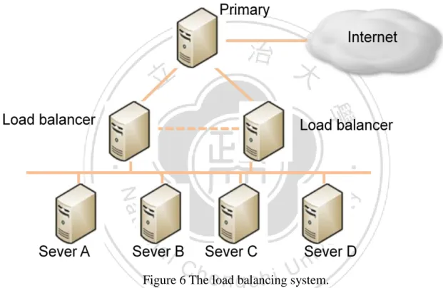
(24) Load balancing is a network method to distribute the network loading across multiple computers. Using lots of computers to work balancing that avoid overloading, and increase the system more reliable. Like Cloud computing, popular web site, FTP systems, DNS servers, it is impossible to handle all the users with a super power server. The system probably spread the services by functional or distribute the users by location. Figure 6 depicts a load balancing system with a primary server.. Figure 6 The load balancing system. According to Figure 6, only primary server connected with the Internet, Load balancer and Server A, B, C and D are behind the primary server. The users ask the primary server to help, and then the primary spread the request to the dedicated server .The user even not to connect with internal server directly, the dedicated send reports of request to the primary. Then primary return the feedback to uses. In this case, we implement a few servers into a simple load balancing system to distribute our music streaming loading, and also handle the NAT problems in our IRIS system.. 14.
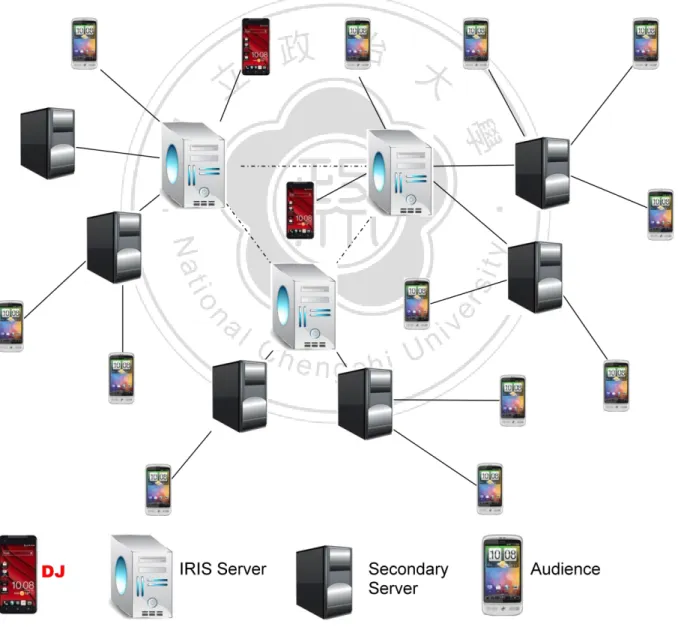
(25) CHAPTER 3 Load balancing IRIS 3.1 IRIS Architecture. Figure 7-1 A load balancing IRIS architecture. 15.
(26) Figure 7-1 depicts a load balancing IRIS architecture. We construct four components in IRIS. IRIS architecture: 1. DJ (Disc jockey): DJ is an anchorman and the main content provider. The DJ produced the talk show in IRIS system, which could play the music and talk about the music or anything they want to say. Also, if someone wants to use call-in service, The DJ has the ability to accept or reject. 2. IRIS Server: it is a primary and dedicated server. It manages the DJ and Audience in system, and provides the advertisement and relay message to audience. Every user should register to the IRIS server before they become a DJ or audience. 3. Secondary Server: the Secondary server would help the IRIS server to work load balancing. When IRIS server is in a heavy load, it would distribute audience to secondary Server. Secondary Server handles the audience being sent from the IRIS server, and then response all request from the audiences. 4. Audience: the general audiences. They could decide what music they want to listen, and be callers by using the call-in service to talk interactively with DJ. Or they also could choose to be DJ.. 16.
(27) Figure 7-2 IRIS architecture with Firewall. Figure 7-2 depicts the architecture with Firewall. Every audiences and DJ connect with Wi-Fi AP and firewall. The firewall is usually contained in Wi-Fi AP because Wi-Fi AP constructed by private network. The network connection links transfer streaming from Wi-Fi AP through the Internet to IRIS Server. Initially DJ joined into system, and then sent the audio and music streaming to IRIS server, IRIS server helps the DJ to relay his streaming into the channel by sending the streaming to every audience who is listening to the channel right away. Their two are the most import roles in IRIS. Every audience could choose to be a DJ. That is a big difference with the other radio applications on Android system or iOS. Figure 8 depicts a simple construction of IRIS. DJ transfers his music streaming to IRIS Server, and IRIS relay the streaming to an audience and 17.
(28) Secondary Server. Secondary serves the audience which connected with.. Figure 8 Simple construction of IRIS. 3.2 IRIS Construction. 3.2.1 DJ Join When an audience chooses to became a DJ, it would send a DJ request connection to the IRIS Server. Figure 9 depicts the flowchart of the DJ join.. 18.
(29) Figure 9 Flowchart of DJ Join. After IRIS Server got a DJ request connection, it executes a channel selection. The selection is checking all the channels if there is an empty channel. That would be a noise if there were two or more DJ playing the music in the same channel. So before we investigate solutions like communication with two DJ or something solving the noise problem, in the IRIS now we observe a principle that must only an anchorman in a channel. If there is no empty channel in IRIS, the IRIS Server would send a reject answer to the DJ. If there is an empty channel, IRIS server would gets the DJ into the empty channel and then lock it avoiding the other DJ get in. And then Server keeps receiving the streaming from DJ. After receiving a buffer of music streaming, Server would search to relay list to find out how many audiences are in this channel, and relay the streaming to all the audience. And DJ is no need to worry about the relay. 19.
(30) The server would maintain relay list when relay the streaming. If the server finds out that the relay link to an audience was dead, which means the audience is leaving the channel no matter how for any reasons. Server would remove the link from the relay list. That is okay for server handling that the audience leaves.. 3.2.2 Audience Join. When a user gets into IRIS, we define that the user will be an audience first. No matter the user chose the channel or not. The audience could select the channels we provided or doing nothing that just stay in the IRIS. When an audience selected the channel, it sends an Audience request connection to IRIS Server. Figure 10 represents the flowchart of Audience Join.. Figure 10 Flowchart of Audience Join. After receiving an audience request connection, the Server would check the channel 20.
(31) up-bound. The channel up-bound was setting to avoid server over load. Because the audiences increase were also increased the server relay loading, so we deploy an simple load balancing solution, and we will discuss it later. If the channel up-bound is not reached, the server would put the audience connection link into relay list and return an okay message to the audience. If the channel up-bound is reached, it would check if there is Secondary server which is working for load balancing. If there is no more Secondary Server to handle with redundant audiences, the IRIS Server would send a reject message to the audience. The audience knows that the channel is busy right away; it would select the same channel later or choose the other channel that is not busy. If there is a Secondary Server could accept redundant audience, the server would give the audience which chose the channel the Secondary Server information include the IP address and listening port. After receiving the new IP address and port, the audience would connect to the Secondary Server. And the Secondary Server runs the same algorithm which the Figure 10 described.. 3.2.3 Call-in. It is unique utilizaion in a radio system over smart phone like we said before. Figure 11 describes the flowchart of Call-in service.. 21.
(32) Figure 11 Flowchart of Call-in service. When audience listened the talk show that produced from DJ, there is a chance that making a Call-in service. If IRIS server got a Call-in request, it would find which DJ is in the channel that the call-in audience selected and search the DJ connection link from DJ list. Then it sends a request to DJ querying the Call-in. If DJ denied the request, then Server response the audience that DJ reject his request. If DJ accepted the Call-in, the audience would be the caller and the IRIS Server would help with relaying their streaming to each other. The channel would start interactive communication between the HOST and the caller, which is VoIP service. And the other audiences are still in this channel, they would hear the communication in the radio.. 3.2.4 Load Balancing Server Relay. When more and more audiences got into the same channel, the IRIS server increases the same 22.
(33) level of work loading. Because IRIS is developed based on TURN algorithm and TURN is the Client-Server architecture. The throughput bottleneck would appear on IRIS Server. In the initial stage of IRIS, we design a simple way of load balancing as the solution with the bottleneck. That answer is that we deploy some Secondary Servers behind the IRIS Server. When IRIS Server is going to or has been over load, it would ask Secondary Servers for help. The IRIS Server would pass the audience to Secondary Server if the Secondary Server has redundant utilities.. Figure 12 Flowchart of Secondary Server service. Figure 12 depicts the flowchart after Secondary Server adopted the audience. First server gets the order from audience; server will check whether there is a streaming which the audience wants. If the answer is yes, which means there is another audience that listened the same channel on Secondary Server. It will relay the streaming right away. If not, the Secondary Server would ask IRIS Server for the streaming that it need, and then relay the 23.
(34) streaming. So if there are N audiences that were listening to the same channel on Secondary Server, the IRIS Server would reduce (N-1) relay connections.. 24.
(35) CHAPTER 4 Implementation 4.1 Reality. Figure 13 The implement devices. 25.
(36) Table 3 Experimental Setup. Figure 13 shows the devices we implemented IRIS on. There are HTC Desire and SAMSUNG Galaxy S i9000. Table 3 describes the environment and experimental setup. The environment is based on Android system and the version 2.2 (API Level 8). The Android phone should be the version 2.2 or later to run IRIS. When we developed the IRIS that was some subjects should be concerned. First, Android does not support the audio library which is in java before. The audio library could help us handling the music format. In real time system we must transform the music format into streaming instead of commonly music format which is like mp3. So we must to develop the transformation by ourselves. But there existed the second problem on smart phone; the CPU rate is usually lower than PC. And not only CPU rate but also cache memory and security. It must be developed careful to avoid that too many threads ran at the same time over smart phone and thread occupied too much CPU time especially the transformation thread. The third subject is NAT Problem that we have been discussed above this chapter.. 4.2 Traversal Using Relay NAT. The NAT solution we adopted is Traversal Using Relay NAT (TURN). Figure 14 depicts a simple concept of TURN and why can’t we implement the P2P connections When DJ has produced the talk show, it is better that audiences connect directly with the DJ 26.
(37) by P2P connection. But there exists a NAT problem. When Audience A and B tried to connect directly with DJ. The NAT device is above the DJ and how does it quit the connection is depend on the NAT type. In commonly the directly connection could not be initial, so instead of the traditional way we developed DJ to send his talk show streaming to IRIS Server. The Audience A connected with IRIS Server instead with the DJ. Of course there exists the same NAT problem between IRIS Server and DJ. IRIS Server could start the connection with DJ only if DJ has been sent a packet to IRIS server before. In case of that, in reality we suppose that DJ is necessary registering his information to IRIS Server before DJ start its talk show. Therefore it solves the initial problem of TURN and also helps us to manage how many DJ is active in IRIS. Figure 14 NAT traversal. 27.
(38) 4.3 Load Balancing System 4.3.1 IRIS without Load Balancing. Figure 15 presents IRIS without Load Balancing. There are four audiences A, B, C and D listening to the same DJ talk show and only one IRIS Server served. If audiences keep increased, the IRIS Server would overload in the expectable time. There are five connections work on IRIS server that one connection is receiving the DJ Streaming and the remained four connections are relaying the Streaming. It means that IRIS Server needs to relay a streaming four times to four different audiences.. Figure 15 IRIS without Load Balancing. 4.3.2 Secondary Server Load Balancing. Figure 16 presents that IRIS works load balancing with Secondary Server. It has deployed 28.
(39) two the secondary servers. Comparisons with Figure 15, there are seven connections in IRIS that are more than Figure 15, but each server (an IRIS server and two Secondary servers) only maintain three connections. The upper Secondary Server in Figure 16 maintains two relay link for Audience A and B. The lower one maintains two remained Audiences. The IRIS Server just relay a streaming twice instead four times. This way reduces the network connections that focus on IRIS Server and balances the loading.. Figure 16 IRIS works load balancing with Secondary Server .. If Secondary Server could communicate with other servers, that could reduce one more connection on IRIS Server as long as the lower Secondary Server asks the upper Secondary Server in Figure 16 for the same streaming instead asking IRIS Server. It can be achieved by 29.
(40) developing communication algorithm between IRIS Server and Secondary Server. But for now, we do not develop a complex algorithm for load balancing. The Secondary Server follow a simple principle that when it got a audience request, it would accepted the request if it has redundant utilities or passed the request to other server until there is no more Secondary Server could be passed, and the final Secondary Server rejects the request finally.. 4.3.3 Three DJ in IRIS. The IRIS provides three DJ channels now; it means that allow three DJ talk shows at most in the same time. In order to make it convenient for management, the IRIS Server would concentrate all the DJ connections for the purpose of the call-in service in the future. In this way of centralization development, IRIS take care of all the DJ connections, and does not need to communication with Secondary Servers to know about how many DJ are on the air in IRIS. The Secondary Servers are only responsible for that audiences were passed from IRIS Server and relay the streaming what audiences want. Figure 17 depicts three DJ are on the air in IRIS. It is similar with one DJ, three DJ connections all connected with the IRIS Server. IRIS Server connected with an audience and two Secondary Servers. In this case, if there is a DJ that wants to join, it would be rejected because all three channels had been taken. If there is an audience that wants to join, it would depend on the two Secondary Servers whether enough utilization had or not.. 30.
(41) Figure 17 Three DJ are on the air in IRIS.. 4.3.4 Call-in In IRIS. Because the DJ connections has been concentrated on IRIS Server, if there is an audience want to make a call-in service, this audience will send a call-in request to IRIS Server directly not through Secondary Server. Then Server would execute this request by the algorithm that Figure 11 represented. Figure 18 depicts the architecture after an audience made a call-in to DJ. When DJ accepted the call-in, the IRIS Server creates a new thread for Caller. This thread relays the streaming that sends form Caller to DJ. But Caller still receives the streaming of DJ that relay from the Secondary Server.. 31.
(42) Figure 18 A audience make a call-in to DJ.. In fact, there were two different ways that Caller could receive streaming from. First is received from IRIS Server directly, it would cause IRIS Server additional network load. Second is received from Secondary Server after IRIS Server sent it to Secondary Server.. 4.4. User Interface. 32.
(43) Figure 19 Flow chart of IRIS. Figure 19 depicts our IRIS program flowchart. First picture is login interface. Second picture is Audience interface; we present its function of buttons in section 4.4.1. The third picture present the DJ interface, we would explain it in section 4.4.2. As the Figure 20 presents, it is the first frame of IRIS. But it is just a login interface; users don’t enter the system yet. In this situation, user should input their account to login, although we do not authenticate the user accounts yet. On the IRIS server screen, we could find out how many users were login into IRIS and saw their account name. Every DJ, Audiences and Caller connection would cause some input of information on screen.. 33.
(44) Figure 20 Login interface. 4.4.1 Audience. As long as users login into IRIS, all users become audience in Audience interface . Figure 21 depicts IRIS Audience interface on Samsung Galaxy S i9000.There provides three channels which are Channel 1, Channel 2 and Test_channel to select. When audiences selected Channel 1 or Channel2, the 59connection thread in IRIS would send a audience request to IRIS server. After Server excuted Audience Join algorithm and accecpted the Audience request, initially the music streaming play button would turn on and play streaming automatically, and then Audience started enjoying the talk show. And now Test_channel will 34.
(45) not accept any DJ to get in. In fact, two channels have been aleady enough to deal with the quanity of smart phone devices we have. The third channel “Test_channel” is not opened temporaily so that make expanding or other broadcast in the future.. Figure 21 Audience interface. The next two buttons are “Play” and “Stop”. If audience listened to talk show and wanted to stop for a while, the button “Stop”could be clicked to stop playing streaming from talk show. It is not stopped or diconnected with Server,the connection was keeping connected. Just the Audience chose to not to listen to the music, the Server that Audience connected still transmited the streaming to that. And if audience wants to restore listening to the talk show, clicking the “Play” button. It would return back to the “Play” situation that restart the IRIS 35.
(46) talk show in real time. The remained three buttons are Call-in, Quit and DJ. When Call-in button was clicked, it would excute the algorithm of the Call-in service that Figure 11 described.After DJ accepted the call-in request, it initially started audio communication which applied for VoIP automatically. When an Audience became to a Caller, the “Play ” and “Stop” buttons still work like being an Audience before, “Play” button refers to start or return back to play, “Stop” button refers to stop listening to the audio streaming recording from DJ. The “Quit” button is functional for disconnecting all the network connections. It means if an audience does not want to listen to talk show anymore or a Caller wants to hang up the call-in, they could click the “Quit” button. It would stop receiving streaming from Server and stop all the network connections. And the point is that “Quit” button only disconnected all network connections, but not leaving the IRIS, so that they are still staying the Audience interface. The “DJ” button would exchange the interface form the audience to the DJ. We will discuss it in next section 4.4.2.. 36.
(47) 4.4.2 DJ. Figure 22 DJ interface. Figure 22 depicts a DJ interface. The three upper buttons are control buttons of music play. “Play” button means that when you click this button, it starts playing the music you stored in smart phone SD card. The “Pause” button would pause on the music playing, until DJ clicked the “Play” button again and then continually play. The “Stop” button will end the music playing. If DJ clicked “Play” after clicked “Stop”, the music player would restart playing the music at the first not in the middle. The bar is music seek bar. It supply to seek the music time by moving the seek bar. When the seek bar is moving, thread that executes in background will. 37.
(48) find out the homologous music streaming time to play the music. The next two buttons is “Record” and “Stop”. Clicking the “Record” button would record all the DJ saying and music playing. And “Stop” button was set to stop record. The remained two “Register” and “Quit” button is relative with IRIS Servers. The Register is set to send a DJ connection request to DJ. After IRIS sever executes the algorithm of DJ Join that describes in Figure 9, DJ will send the record streaming to IRIS Server if the answer is “accept” and the “Record ” button has been clicked. If there is not in “Record” situation or the DJ request is rejected, DJ can still play the music and record the streaming without crash, but not sending to anyone. The “Quit” button is the same action with the “Quit” in Audience interface. It is clicked by DJ to disconnect with IRIS Server. It means the DJ that want to quit the talk show. If the DJ wants to continue his talk show, it has to register in IRIS Server again competing for the empty channel. The IRIS Sever will check the channel is empty by checking the connection with DJ. If the connection is gone, IRIS Server would clean the channel and set it empty to let other DJ get in.. 38.
(49) CHAPTER 5 Conclusions and Future Work. In this thesis, we implement IRIS, Interactive 2.0 Radio System on the Internet over Smart phone. In IRIS, there are two unique improvements in traditional Radio and VoIP systems. First, everyone could be a DJ to create a unique talk show. Second, Audience could make a call-in service to DJ. By achieving our purposes, we traverse the NAT problems above the smart phones. And because network load focus on our IRIS Server, we deploy a simple load balancing system to ease off the IRIS Server load. The streaming data were raw data that sends and receives between nodes in IRIS. Therefore in the future we propose to make some lossless compression or transform the format to RTSP (Real Time Streaming Protocol) [21]. And there is a Wi-Fi direct [22] technique that support on Android 4.0(API level 14). This technique can make audience connected directly without AP. When IRIS Server and Secondary Server both have no redundant utilization for relay, Wi-Fi direct can help audience to connect with each other for sharing streaming. Besides, we hope to develop IRIS in the Cloud in the future.. 39.
(50) Reference [1] RFC1631 The IP Network Address Translator (NAT) [2] RFC2663 IP Network Address Translator (NAT) Terminology and Considerations [3]. Network. Address. Translation. (NAT). Protocol.. http://www.tcpipguide.com/free/t_IPNetworkAddressTranslationNATProtocol.htm [4]RFC2709 Security Model with Tunnel-mode IPsec for NAT Domains [5]RFC3022 Traditional IP Network Address Translator (Traditional NAT) [6]RFC3027 Protocol Complications with the IP Network Address Translator (NAT) [7] M. E. Baran and F. F. Wu "Network Reconfiguration in Distribution Systems for Loss Reduction and Load Balancing", IEEE Transactions on Power Delivery, vol. 4, no. 2, pp.1401 -1407 1989 [8]M. Cierniak, M.J. Zaki and W. Li, &ldquo, Customized Dynamic Load Balancing for a Network of Workstations, &rdquo, J. Parallel and Distributed Computing, vol. 43, pp. 156-162, 1997. [9] Siuli Roy , Dola Saha , S. Bandyopadhyay , Tetsuro Ueda , Shinsuke Tanaka, A network-aware MAC and routing protocol for effective load balancing in ad hoc wireless networks with directional antenna, Proceedings of the 4th ACM international symposium on Mobile ad hoc networking & computing, June 01-03, 2003, Annapolis, Maryland, USA [10] TuneIn Radio http://tunein.com/ [11] Pandora http://www.pandora.com/ [12] Skype http://www.skype.com/ 40.
(51) [13] Line http://line.naver.jp [14] S. Baset and H. Schulzrinne. An analysis of the skype peer-to-peer internet telephony protocol. Technical Report CUCS-039-04, Computer Science Department, Columbia University, New York, NY, Sep 2004. [15] RFC 5389, J. Rosenberg, R. Mahy, P. Matthews, D. Wing, Session Traversal Utilities for NAT (STUN), The Internet Society (October 2008) [16] RFC5766, R. Mahy, J. Rosenberg, C. Huitema. TURN: traversal using relay NAT. Internet draft, Internet Engineering Task Force, July 2004. Work in progress [17] RFC 6062, J. Rosenberg, S. Perreault, Ed. Traversal Using Relays around NAT (TURN) Extensions for TCP Allocations. Internet draft, Internet Engineering Task Force, [18] RFC 6156, G. Camarillo Ericsson, O. Novo, S. Perreault, Ed., Traversal Using Relays around NAT (TURN) Extension for IPv6 (April 2011) [19] RFC 5245, Interactive Connectivity Establishment (ICE): A Protocol for Network Address Translator (NAT) Traversal for Offer/Answer Protocols, J. Rosenberg (April 2010) [20] RFC 3489, STUN - Simple Traversal of User Datagram Protocol (UDP) Through Network Address Translators (NATs), J. Rosenberg, J. Weinberger, C. Huitema, R. Mahy, The Internet Society (March 2003). [21] RFC 2326 Real Time Streaming Protocol (RTSP). [22] Wi-Fi Direct http://developer.android.com/guide/topics/connectivity/wifip2p.html. 41.
(52)
數據


+7

相關文件
bility of the mobile system is the same as the call blocking For example, for a hexagonal planar layout with reuse dis- probability in a cell, Because traffic in
• A knock-in option comes into existence if a certain barrier is reached?. • A down-and-in option is a call knock-in option that comes into existence only when the barrier is
• Similar to futures options except that what is delivered is a forward contract with a delivery price equal to the option’s strike price. – Exercising a call forward option results
• What is delivered is now a forward contract with a delivery price equal to the option’s strike price.. – Exercising a call forward option results in a long position in a
Lemma 2 An American call or a European call on a non-dividend-paying stock is never worth less than its intrinsic value.. • An American call cannot be worth less than its
• A knock-in option comes into existence if a certain barrier is reached.. • A down-and-in option is a call knock-in option that comes into existence only when the barrier is
• Similar to futures options except that what is delivered is a forward contract with a delivery price equal to the option’s strike price. – Exercising a call forward option results
• Similar to futures options except that what is delivered is a forward contract with a delivery price equal to the option’s strike price.. – Exercising a call forward option results
