LTE 系統下感知式 Femtocell 之優先次序資源管理機制
A Priority-based Resource Management Scheme
for Cognitive Femtocell in LTE System
研 究 生:葉長青 Student:Chang-Cing Ye
指導教授:張仲儒 博士 Advisor:Dr. Chung-Ju Chang
國立交通大學
電信工程研究所
碩士論文
A Thesis
Submitted to Institute of Communication Engineering
College of Electrical and Computer Engineering
National Chiao Tung University
in Partial Fulfillment of the Requirements
for the Degree of Master of Science
in
Communication Engineering
July 2012
Hsinchu, Taiwan
i
LTE 系統下感知式 Femtocell 之
優先次序資源管理機制
研究生:葉長青 指導教授:張仲儒 博士
國立交通大學電信工程研究所
Mandarin Abstract摘要
由於宏細胞(macrocell)無法提供足夠的服務給室內用戶,家庭基站(femtocell) 被提出來改善室內用戶的服務效能。然而,家庭基站的佈建會對宏細胞系統造成 無法預期的感擾,並降低周遭室外用戶的服務效能。為了解決這個難題,混合式 接取技術被視為一個大有可為的解決方法。混合式接取技術使家庭基站能夠去服 務周遭的室外用戶,並卸載宏細胞的電信業務。 在本篇論文中,我們提出感知優先次序資源分配(cognitive priority-based resource management, CPRM)機制,意圖最大化感知式家庭基站的傳輸量,並保 證滿足各種電信業務的服務品質要求。CPRM 機制會動態調整感測時間以達到準 確的感測結果、設計優先次序來表明用戶需要服務的緊急程度、決定用戶的最小 傳輸位元數來滿足用戶的服務品質要求。然後,CPRM 機制會依照優先次序分配 資源以避免違反緊急用戶的服務品質要求。模擬結果顯示我們提出的 CPRM 機 制能達到比傳統機制高的系統傳輸量,並保證滿足各種電信業務的服務品質需 求。ii
A Priority-based Resource Management Scheme
for Cognitive Femtocell in LTE System
Student: Chang-Cing Ye Advisor: Dr. Chung-Ju Chang
Institute of Communication Engineering
National Chiao Tung University
English AbstractAbstract
Since macrocells cannot provide enough services to indoor users, femtocell is proposed to improve the service performance of indoor users. However, the deployment of femtocell would cause unexpected interference to the macrocell system, and degrade the performance of the nearby outdoor users. To overcome this challenge, hybrid access policy is envisioned as a promising solution. Hybrid access policy enables femtocell to serve the nearby outdoor users and offload the traffic of macrocell system.
In this thesis, we propose a cognitive priority-based resource management (CPRM) scheme to maximize the throughput of cognitive femtocells with guaranteeing the quality-of-service (QoS) requirements of all traffic types. The CPRM scheme adapts the sensing duration to achieve accurate sensing result, designs the priority function to indicate the degree of urgency of users, and determines the minimum transmission bits to satisfy the QoS requirements of each user. Then, the CPRM scheme would allocate resource based on the priority to avoid violating the QoS requirements of urgent users. Simulation results show that the proposed CPRM scheme achieves higher system throughput than the conventional schemes with guaranteeing the QoS requirements of all traffic types.
iii Acknowledgement
誌 謝
這篇碩士論文的完成,必須感謝非常多人的幫助與鼓勵。首先要感謝張仲儒 教授這兩年多來在專業知識、待人處世與人生規劃上的悉心指導,讓我在學業和 生活上都獲益良多。除此之外,還要感謝文敬學長不遲辛勞地給予指導及督促。 感謝聖章、耀興、振宇、益興學長們,在我研究上遇到困難的時候,能夠提供我 寶貴的意見。還有在進實驗室時熱情歡迎我們的學長,苡仲、俊魁和竣威。當然, 還要感謝和我一起努力的同學們,佩珊、恆皜、兼源、莫瑞,以及辛苦的助理玉 棋、佳婷。有你們的陪伴,研究的路途多了很多的歡笑。祝福實驗室的大家,學 業都能順利,畢業後一帆風順。 最後,我要感謝我最摯愛的父母、兄弟,以及所有關心我、陪伴我、支持 我的親友們,他們對我的支持,使我有動力完成碩士的學業。 葉長青 謹誌 民國一 0 一年七月iv
Contents
Mandarin Abstract ... i
English Abstract ... ii
Acknowledgement ... iii
Contents ... iv
List of Figures ... vi
List of Tables ... viii
Chapter 1 Introduction ... 1
1.1 Motivation ... 1
1.2 Thesis Organization ... 6
Chapter 2 System Model ... 8
2.1 Macro-Femto Networks ... 8
2.2 Channel Model ... 10
2.3 Radio Sensing and Power Allocation Mechanism ... 11
2.4 Traffic Model ... 12
Chapter 3 Cognitive Priority-based Resource Management Scheme
for Macro- Femto Networks ... 16
3.1 Problem Formulation ... 17
3.2 Cognitive Priority-based Resource Management Scheme ... 20
3.2.1 Cognitive Channel Determination Algorithm ... 21
3.2.2 Priority and Minimum Bits Determination Algorithm ... 22
3.2.3 Priority-based Resource Allocation Algorithm ... 25
3.2.4 Summary of The CPRM Scheme ... 26
Chapter 4 Simulation Results ... 29
4.1 Simulation Environment ... 29
v
4.3 Conventional Schemes ... 32
4.3.1 Decomposition-based Resource Management Scheme ... 33
4.3.2 Cognitive Radio Resource Management Scheme ... 34
4.4 System Parameters Adjustment ... 35
4.5 Performance Evaluation ... 43
4.5.1 Cell-edge region scenario ... 44
4.5.2 Entire region scenario ... 53
Chapter 5 Conclusions ... 59
Bibliography ... 61
vi
List of Figures
Figure 2.1: Macro-Femto networks. ... 8
Figure 2.2: Femto block. ... 9
Figure 2.3: Downlink transmission frame structure. ... 10
Figure 2.4: Voice traffic model. ... 13
Figure 2.5: Video traffic model. ... 14
Figure 2.6: HTTP traffic model. ... 14
Figure 2.7: FTP traffic model. ... 15
Figure 3.1: The HeNB with the CPRM scheme. ... 21
Figure 4.1 (a) Throughput of UEs, (b) throughput of HUEs, and (c) throughput of MUEs in the macro-femto and pure macro networks ... 36
Figure 4.2 (a) Throughput of UEs, (b) throughput of HUEs, and (c) throughput of MUEs ... 37
Figure 4.3 Packet dropping rate of (a) voice and (b) video UEs. ... 38
Figure 4.4 Packet dropping rate of (a) voice HUEs and MUEs, as well as (b) video HUEs and MUEs... 39
Figure 4.5 (a) Throughput of UEs, (b) throughput of HUEs, and (c) throughput of MUEs ... 40
Figure 4.6 Packet dropping rate of (a) voice and (b) video UEs. ... 41
Figure 4.7 Packet dropping rate of (a) voice HUEs and MUEs, as well as (b) video HUEs and MUEs... 42
Figure 4.8 (a) Average transmission rate of HTTP UEs, as well as (b) HTTP HUEs and MUEs ... 43
Figure 4.9 (a) Percentage of failed allocation and (b) average sensing duration. ... 45
Figure 4.10 (a) Throughput of UEs, (b) throughput of HUEs, and (c) throughput of MUEs ... 46
Figure 4.11 Packet dropping rate of (a) voice and (b) video UEs. ... 47
Figure 4.12 Packet dropping rate of (a) voice HUEs and MUEs, as well as (b) video HUEs and MUEs... 48
Figure 4.13 Average packet delay of (a) voice and (b) video UEs. ... 49
Figure 4.14 Average packet delay of (a) voice HUEs and MUEs, as well as (b) video HUEs and MUEs... 50
Figure 4.15 (a) Average transmission rate of HTTP UEs, as well as (b) HTTP HUEs and MUEs ... 51
vii
Figure 4.17 (a) Throughput of UEs, (b) throughput of HUEs, and (c) throughput of MUEs ... 54 Figure 4.18 Packet dropping rate of (a) voice and (b) video UEs. ... 55 Figure 4.19 Packet dropping rate of (a) voice HUEs and MUEs, as well as (b) video
HUEs and MUEs... 56 Figure 4.20 Average transmission rate of HTTP UEs. ... 57 Figure 4.21 Throughput of (a) FTP traffic, (b) FTP HUEs, and (c) FTP MUEs. ... 58
viii
List of Tables
Table 4.1: Parameters of the macro-femto networks. ... 30
Table 4.2: Video traffic model parameters. ... 31
Table 4.3: HTTP traffic model parameters. ... 31
Table 4.4: FTP traffic model parameters. ... 32
1
Chapter 1
Introduction
1.1 Motivation
With the development of wireless communication techniques, the wireless communication networks have integrated into our daily life and changed our life style in depth. In order to support a large number of multimedia services, the fourth generation (4G) wireless communication technique was developed from the 3G wireless communication technique [1]-[3]. Among 4G wireless communication standards, long term evolution - advanced (LTE-A) has caught lots of attention, and becomes the main- stream in the development of 4G wireless communication network [4], [5]. The LTE-A system adopts orthogonal frequency division multiple access (OFDMA) technique to provide the degree of freedom in the exploitation of time-frequency resource units. Therefore, it can achieve better resource efficiency, mitigate the inter- or intra-cell interference, and achieve high signal-to-interference- and-noise-ratio (SINR) [5]-[7]. However, due to the penetration loss of walls, the indoor user usually has poor SINR and thus cannot obtain the enough service. As a result, enhancing the received signal quality of indoor users is still an important issue for the LTE-A system.
Femtocell is a promising technique proposed for enlarging the indoor coverage and thus improving the performance of indoor users. Femtocell is a low-power, low-cost, and small-area base station. In the LTE-A system, the femtocell base station
2
is also called HeNB (home enhanced Node-B or home evolved Node-B). It can connect to the operator’s cellular network by the broadband network or the digital subscriber line (DSL), and transmit data with the internet protocol (IP) technique. For the operator, the deployment of femtocell can extend the indoor coverage, increase the spectral utilization, lower the power consumption, and enhance the transmission efficiency and reliability in the macrocell network [8], [9].
Since there is wireless fidelity (Wi-Fi) technology utilized for indoor communi- cation, the comparison between femtocell and Wi-Fi is discussed [10]. Due to the fact that femtocell is operated on the licensed frequency bands, and Wi-Fi is operated on the un-licensed ones, femtocell can achieve better voice quality and securer services than Wi-Fi. Because femtocell is the extension cellular network, it manages service and QoS more efficiently than Wi-Fi, and also it consumes less power than Wi-Fi. Moreover, femtocell is compatible to the existing cellular networks, so it enables seamless handover between macrocell network and femtocell network, while Wi-Fi needs additional handover trigger to switch between different networks.
The access policy of femtocell can be categorized into open access, closed access, and hybrid access [11], [12]. The open access policy indicates that all user equipments (UEs), included home UEs (HUEs) and macro UEs (MUEs), are allowed to connect to HeNB. Thus, the open access policy can improve the overall throughput of network, since MUEs could connect to nearby HeNB when the macrocell base station, called macro eNB (MeNB), could not provide sufficient service quality. However, the open access policy needs a large number of handovers and signaling between HeNBs and MUEs. This reduces the performance of HeNB. The closed access policy means that only the subscribed HUEs are permitted to access the HeNB. Although it could avoid a large number of handovers and signaling between HeNBs and MUEs, it will generate a severe interference to the nearby MUEs. On the other hand, the hybrid
3
access policy is the combination of the open access policy and closed access policy. The hybrid access HeNB allows non-subscribed MUEs to use some radio resource to get a basic service. However, the most radio resource of hybrid access HeNB is still allocated to the subscribed HUEs to guarantee their quality-of-service (QoS) requirements.
In the macro-femto system, the channel deployment can be sorted into co-channel deployment, dedicated channel deployment, and partial co-channel deployment [13], [14]. The co-channel deployment means that MeNB and HeNB use the same frequency band to serve their UEs. Although this deployment could enhance the spectral efficiency, it also generates a severe interference between macro and femto networks. On the other hand, the dedicated channel deployment means that MeNB and HeNB use different frequency bands to serve their UEs. The dedicated channel deployment could eliminate the interference to and from macro network. However, it wastes the scare spectrum. As for the partial co-channel deployment, it divides the whole spectrum into two parts. One part is dedicated for MeNB only, and the another part is shared between MeNB and HeNB. The performance of different dividing ratio on the whole spectrum was discussed in [13]. Furthermore, the power control scheme for HeNB can be classified into fixed power scheme and adaptive power scheme. The former indicates that HeNB uses a fixed transmission power to deliver data, and the later indicates that HeNB sets its transmission power according to the variety of the environment.
The HeNB is a user-installed base station. Although the user-installed HeNB is convenient for customers and reduces the cost for operators, the operator cannot know the topology of the randomly deployed HeNBs. This makes that the macrocell system suffers an unexpected interference when MeNB and HeNBs use the same frequency band. Especially when MUE is in the cell-edge region of MeNB, the suffered
4
interference from HeNBs would make it be out of service. Since there is no connection between MeNB and HeNB, the MeNB cannot inform the HeNB that it generates the interference to MeNB and request it to reduce its transmission power or change its operated frequency.
In order to solve the interference problem and keep the data rate of MUEs under the deployment of co-channel HeNB, Chandrasekhar et al. proposed a utility-based femtocell SINR adaptation scheme by adopting game theory [15]. Here, the utility function is composed of SINR-based reward and penalty, which are related to the interference at the macrocell. Rahman et al. proposed an interference avoidance algorithm in [16], which adopted Hungarian algorithm to design a maximum sum utility. Jo et al. in [17] discussed two interference mitigation strategies for co-channel HeNB to achieve throughput gain. The first strategy adopted the open-loop approach to suppress the cross-tier interference caused by HeNB. The second strategy used the closed-loop approach to satisfy an adaptive interference threshold according to the noise and interference at MeNB. Moreover, in order to avoid the handover of outdoor MUEs, they proposed a coverage coordination scheme for co-channel HeNB based on the measured signal and interference power at HeNB [18]. On the other hand, according to the outage probability of MUEs, Chu et al. proposed a distance-based strategy, which is based on the distance between the closest MeNB, for co-channel HeNB to self-regulate its transmission power and usage of resource [19].
In recent years, cognitive radio (CR) technique is integrated into HeNB to enhance the spectral efficiency of the macro-femto networks [20], [21]. By the definition of Haykin [22], the cognitive radio is an intelligent wireless communication
system that is aware of its surrounding environment (i.e., outside world), and uses the methodology of understanding-by-building to learn from the environment and adapt its internal states to statistical variations in the incoming RF stimuli by making
5
corresponding changes in certain operating parameters (e.g., transmit-power, carrier-frequency, and modulation strategy) in real-time, with two primary objectives in mind: highly reliable communications whenever and wherever needed; efficient utilization of the radio spectrum. Thus, the CR-enabled HeNB has the cognitive
capability to sense the varying environment, the self-organized capability to analyze and learn from the sensing information, and the reconfigurable capability to use the radio resource flexibly. Therefore, it can adapt to the communication environment and satisfy the network requirements.
There are still some research directions and open issues in the integration of cognitive radio and HeNB [23], such as hardware/firmware modifications, signaling protocol in the femtocell system, inter-working between macro- and femtocell system, business models for open and dynamic access, and the service aspects – authentication, authorization, and accounting (AAA). However, only based on the well-designed resource management scheme and network architecture, operators can achieve the best performance of macro-femto networks more efficiently.
However, the centralized resource management scheme is unrealizable due to the huge number of signaling overhead between MeNB and HeNBs. Therefore, a distributed resource management scheme is suitable for the macro-femto networks. Li et al. proposed a flexible spectrum reuse scheme to solve the interference at femtocell system by adopting the cognitive technique [24]. It was adaptive to the environment by recognizing the interference signature from the network, and minimizing the sum of power on the scheduled spectrum. Sahin et al. utilized the scheduling information and spectrum sensing results to decide whether the sub-carriers were occupied so as to reduce both co-channel interference and inter-carrier interference [25]. In [26], da Costa et al. adopted fractional power control [27] as the power control strategy and game-based resource allocation in cognitive environment [28] as the dynamic
6 spectrum sharing scheme.
Moreover, in order to efficiently execute the radio resource management, the sensing period scheduling was discussed in [29]. Here, the authors studied the QoS-guaranteed sensing period and proposed a resource block allocation scheme. In [30], the strategic game-based resource block management scheme and Gibbs sampler-based resource block management scheme were discussed to mitigate interference among femtocells. Moreover, Cheng et al. analyzed three different resource allocation approaches for CR-enabled HeNB to achieve different levels of spatial reuse [31].
1.2 Thesis Organization
Because there is no connection between MeNB and HeNB, and the available radio resource is insufficient, the interference induced by the closed access HeNBs would degrade performance of its nearby MUEs. Recently, the development of hybrid access femtocell is proposed to solve this problem [32]-[35], and thus HeNB can serve some of its nearby MUEs to offload the traffic of macrocell system, while the hybrid access HeNB has provided service to its HUEs. However, in order to utilize the available radio resource efficiently, and mitigate interfering with neighbor eNBs and UEs, we adopt the cognitive radio technology into our resource management scheme. Also, in order to guarantee the QoS requirements of HUEs, we adopt the priority-based service discipline into our resource management scheme. Therefore, the proposed cognitive priority-based resource management (CPRM) scheme aims to maximize the system throughput of hybrid access HeNB with guaranteeing the QoS requirements of all traffic types.
The remainder of this thesis is organized as follows. Chapter 2 introduces the considered system environment. And, Chapter 3 formulates the resource management
7
problem of cognitive HeNB in the hybrid access policy, as well as presents the proposed CPRM scheme. Then, the simulation results are provided and analyzed in Chapter 4, and we would conclude our work in Chapter 5.
8
Chapter 2
System Model
2.1 Macro-Femto Networks
In LTE-A system [36], the macrocell system is a hexagonal grid structure with an MeNB located in the center of coverage, and can be partitioned into three equivalent sectors as illustrated in Figure 2.1. This partition architecture can prevent cell-edge UEs from interference induced by contiguous cell, while we adopt different frequency bands in the three sectors. Since we assume each sector is operated on different frequency bands, and there is the same number of femto blocks randomly overlaid in each sector, we would only focus on one sector of macrocell. Besides, we define the cell-edge region of MeNB as the region where is apart from MeNB by more than four-fifths of its radius.
Figure 2.1: Macro-Femto networks. : femto block : MeNB
9
Furthermore, the femto block is based on dual-strips model and has only one floor for simplicity as shown in Figure 2.2. The femto block consists of 40 apartments, and each apartment can be randomly deployed with one HeNB at most. The deployment ratio of a femto block, denoted by rd, indicates a ratio of the deployed
number of HeNBs over the 40 apartments. As illustrated in Figure 2.2, HUEs are uniformly distributed inside apartments, and MUEs are uniformly distributed outside apartments, while there are a set of Ψf HUEs and a set of Ψm MUEs in the K serving UEs of hybrid access HeNB.
10m 10m
10m
10m 10m
: HeNB : MUE : HUE
Figure 2.2: Femto block.
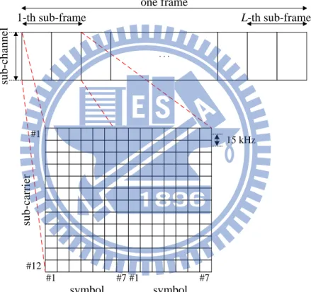
Moreover, we consider the frequency division duplexing (FDD) frequency operation mode, and only focus on the downlink transmission bandwidth, denoted by
BW. The downlink transmission frame structure is shown in Figure 2.3 [37]. Each
frame comprises L sub-frames, one sub-frame lasts 2 time slots, and there are 7 symbols in a time slot. The BW is divided into N sub-channels, each sub-channel is grouped by 12 adjacent orthogonal sub-carriers, and each sub-carrier individually spaces 15 kHz. The basic resource unit is sub-frame, and each resource unit contains
10
Ne allocation units. We assume each sub-channel has flat channel response bandwidth, denoted by BWsc, in a frame duration. Thus, the fading effect coefficients remain constant in each frame, and change from one frame to another one. Under the assumption of the perfect frame synchronization, the cross-talk between frames and inter-symbol interference (ISI) inside frame are neglected. And, the precise OFDM receiver is also supposed to ignore the inter-carrier interference by the property of orthogonality. one frame 1-th sub-frame #12 su b -c h an n el #1 su b -c ar ri er #1 symbol #7 . . . L-th sub-frame 15 kHz #1 #7 symbol
Figure 2.3: Downlink transmission frame structure.
2.2 Channel Model
The wireless fading channel is composed of path-loss, short-term fading, and long-term fading. However, we adopt the path-loss model from [36], and express the path-loss (PL) between receiver R and transmitter T by
1 2log ( )10 , 10 20 w, L L d L R T PL (2.1)
11
where d is the distance in meters between receiver R and transmitter T, L1= 15.3 and L2= 37.6 when receiver R is not in the same apartment stripe as transmitter T, L1=
38.46 and L2= 20 when receiver R and transmitter T are in the same apartment stripe,
and Lw is the penetration loss caused by the walls in the path between receiver R and transmitter T. The short-term fading (JM) between receiver R and transmitter T on the sub-channel n at time t is modeled by Jakes model [38] with Mo oscillators as:
, 1 2 2 cos 2 cos( ) 4 2 cos 2 sin( ) , 4 o M R T n D m o o D o m JM f t M M m f t M (2.2)
where fD is the Doppler frequency, while θ, ϕ, and φ are statistically independent and uniformly distributed on [-π, π). Moreover, the long-term fading (SF) between receiver R and transmitter T on the sub-channel n is modeled by shadow fading model, which is a log-normal distribution with mean of zero and standard deviation (STD) of
SH
as: , 10 20SH R T n SF , (2.3)where δ is a standard normal distributed variable. Therefore, the channel gain between the receiver R and transmitter T on sub-channel n can be expressed by
, , , ,
R T R T R T R T
n n n
h PL JM SF . (2.4)
2.3 Radio Sensing and Power Allocation Mechanism
By CR technique, HeNB would sample the radio environment many times in a sub-frame duration, and the sensed received signal strength (RSS) on sub-channel n is denoted by RSSn and given by
2 , 0 , 1 \ 1 , n L F T T n n n l l T F n RSS h P N L (2.5)
12
where Ln is the number of sub-frames required for HeNB to sense sub-channel n, Ω is the set of total eNBs in a sector, P n lT, is the transmitted signal power of transmitter T on the sub-channel n in the l-th sub-frame, and N0 is the background noise power per
sub-channel. Besides, the channel state of sub-channel n, denoted by sn, is set to be 1 if the signal power on sub-channel n is less than or equal to the threshold of RSS on sub-channel, denoted by RSSth, and 0 otherwise.
HeNB may misjudge the channel state and thus cause false alarm or mis-detection problem. False alarm indicates that HeNB misjudges the available radio resource is unable to use, and mis-detection indicates that HeNB misjudges the unavailable radio resource can be used. Therefore, the probability of false alarm and mis-detection, denoted by Pf and Pm, can be expressed as Pf = Prob{RSSn > RSSth | sn = 1} and Pm = Prob{RSSn ≤ RSSth | sn = 0}.
However, given the sensed RSSn on sub-channel n and the required SINR for HeNB to transmit b bits to UE k, denoted by SINRk b*, , which is given by
* , ln(5 ) (2 1) 1.5 b k k b BER SINR , (2.6)
where the required BER of UE k is denoted by BERk, the transmission power of HeNB F on sub-channel n at the l-th sub-frame is determined by
* , , 2 , F n n l k b k F n RSS P SINR h , (2.7)
thus HeNB can transmit bits to its serving UEs and satisfy their BER require- ments.
2.4 Traffic Model
Since the storage capacity of eNBs can be enhanced easily by hardware devices, we basically assume that each serving UEs of eNB has infinite buffer. Because multiple services are provided by operators, various service traffics are proposed with
13
individual characteristics and requirements [39]. We focus on the four most common traffic types, which are voice traffic of real-time (RT) service, video traffic of RT service, HTTP traffic of non-real-time (NRT) service, and FTP traffic of best effort (BE) service.
Although every traffic has the BER requirement, RT service also has the maximum delay tolerance requirement, and NRT service also has the minimum transmission rate requirement. However, the delay of head-of-line (HOL) packet of UE k is denoted by Dk in unit of frames, which is from the arrival of its HOL packet to the current frame, and the maximum delay tolerance of UE k is denoted by D in k*
unit of frames. Besides, the transmission rate of the UE k to the current frame is denoted by Rk, and its minimum transmission rate is denoted by R . For RT UE, its k*
packet would be dropped if the packet violates its maximum delay tolerance.
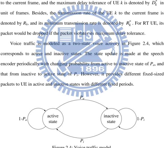
Voice traffic is modeled as a two-state voice activity in Figure 2.4, which corresponds to active and inactive states. The state update is made at the speech encoder periodically with changing probability from active to inactive state of Pa, and that from inactive to active state of Pi. However, it provides different fixed-sized packets to UE in active and inactive states with different fixed periods.
1-Pi active state inactive state Pa Pi 1-Pa
Figure 2.4: Voice traffic model.
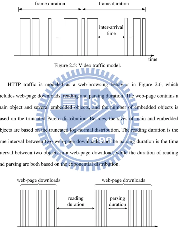
Video traffic is modeled as a stable video frame flow in Figure 2.5. It provides a fixed duration and a constant number of packets in one video frame duration.
14
Moreover, the packet size and the inter-arrival time between packets in a video frame are both based on the truncated Pareto distribution.
time
... ...
frame duration frame duration
inter-arrival time
Figure 2.5: Video traffic model.
HTTP traffic is modeled as a web-browsing behavior in Figure 2.6, which includes web-page downloads, reading and parsing duration. The web-page contains a main object and several embedded objects, and the number of embedded objects is based on the truncated Pareto distribution. Besides, the sizes of main and embedded objects are based on the truncated log-normal distribution. The reading duration is the time interval between two web-page downloads, and the parsing duration is the time interval between two objects in a web-page download, while the duration of reading and parsing are both based on the exponential distribution.
web-page downloads web-page downloads
main object embedded objects reading
duration
parsing duration
time
15
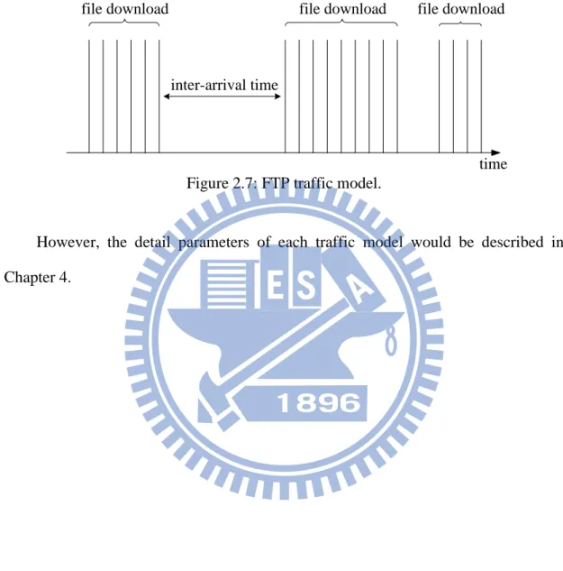
FTP traffic is modeled as a sequence of file downloads in Figure 2.7. Its file size is based on the truncated log-normal distribution, and the inter-arrival time between two successive files is based on the exponential distribution.
file download
inter-arrival time
file download file download
time
Figure 2.7: FTP traffic model.
However, the detail parameters of each traffic model would be described in Chapter 4.
16
Chapter 3
Cognitive Priority-based Resource
Management Scheme for Macro-
Femto Networks
Since the HeNB has the ability of cognitive radio, it could sense all sub-channels and choose the most suitable sub-channels to avoid interfering with MeNB and the neighboring HeNBs. Once the HeNB determines the available sub-channels to transmit data, it allocates sub-channels, modulation order, and power to its serving UEs. Moreover, the HeNB could serve HUEs and MUEs since it adopts the hybrid access policy. Each UE has its QoS requirements, which should be guaranteed by the resource management scheme. Therefore, the problem of radio resource management for the hybrid access HeNB with the ability of cognitive radio is very complex due to its multiple degree of freedom.
In this thesis, we adopt the priority-based service discipline to design a resource management scheme, which determines the priority value to each UE and then serves UEs based on their priority values. In order to maximize the throughput of HeNB and guarantee QoS requirements of its serving UEs, we first formulate the resource management problem of hybrid access HeNB to an optimal problem in the following. After that, we propose a cognitive priority-based resource management (CPRM) scheme to find a sub-optimal solution for this optimal problem.
17
3.1 Problem Formulation
Define b n lk, as the number of transmission bit on one sub-carrier for UE k with
M-QAM modulation on sub-channel n at the l-th sub-frame, where bn lk, log2Mand
, 0, 2, 4,6
k n l
b , 1 ≤ k ≤ K, 1 ≤ n ≤ N, and 1 ≤ l ≤ L. If bn lk, 0, it indicates that HeNB does not transmit bits to UE k on sub-channel n at the l-th sub-frame. On the other hand, if bn lk, 2, 4, or 6 , it indicates that HeNB transmits data to UE k with the modulation order of QPSK, 16-QAM, or 64-QAM, respectively, on sub-channel n at the l-th sub-frame. Therefore, the total throughput of UE k at the current frame can be obtained by , 1 1 ( k) L N n lk e n, , n l C b N s k b (3.1) where 1,1 1, 1, , , ,1 , 1 ( ). k k k k k k k n L N L L L N k b b b bn l b b b L N b
In the hybrid access HeNB, we should consider the following two QoS fulfillment constraints to guarantee the QoS requirements of UEs and four system constraints to satisfy the limitation of HeNB.
(i) QoS Fulfillment Constraint for RT service
Since the RT UE k has the QoS requirements of the maximum delay tolerance, the delay of its HOL packet, Dk, should be less than or equal to D . k*
We then have
*,
RT k k
D D k , (3.2)
where ΨRT is the set of RT UEs.
(ii) QoS Fulfillment Constraint for NRT service
Since the NRT UE k has the QoS requirements of the minimum transmission rate, its transmission rate, Rk, should be larger than or equal to R .k* We then have
18 *,
NRT k k
R R k , (3.3)
where ΨNRT is the set of NRT UEs. Note that, since BE UE only has the QoS requirement of BER and the BER requirement can be easily fulfilled by setting its transmission power, we do not consider the QoS fulfillment constraint for BE service here.
(iii) Sub-channel Allocation Constraint
In the macro-femto system, a sub-channel can be allocated to at most one UE at each sub-frame, since HeNB is only equipped with one transmit antenna. Thus, the sub-channels allocation constraint is given by
, 1 sgn( ) 1, , . K k n l k b n l (3.4)
(iv) Power Budget Constraint
The total power allocation for downlink data transmission at HeNB should have a limitation. Let P* be the maximum transmission power. We then have the power budget constraint as
* , 1 , . N F n l n P P l (3.5)
(v) Cognitive Sub-channel Availability Constraint
The sub-channel n is regarded as available if the detected RSSn is less than or equal to the threshold of RSS, RSSth. Hence, the cognitive sub-channel availability constraint can be expressed by
, 0, if , , , .
k
n
n l th
b RSS RSS k n l (3.6)
(vi) HUE QoS Satisfaction Constraint
In order to avoid violating the QoS requirements when UE is urgent, each UE should transmit some bits at each frame. Since HeNB is mainly established to serve HUEs, the QoS requirements of HUEs must be guaranteed first. Let γk
19
be the minimum transmission bits of UE k at the current frame. We then have the HUE QoS satisfaction constraint by
, 1 1 . , L N k e n l k f n l b N k (3.7)
Let B = [b1…bk…bK] be the allocation result of HeNB at the current frame. The
resource management problem of HeNB can be formulated to an optimal problem as follows, * , 1 1 1 arg max K L N n lk e n, n k l b N s B B (3.8) subject to
QoS fulfillment constraints: * * (i) , , (ii) , , RT k k NRT k k D D k R R k
and system constraints:
, 1 * , 1 , , 1 1 sgn( ) 1, , , (i) , , (ii) 0, if , , , , (iii) , . (iv) K k n l k N F n l n k n n l th L N k e n l k f n l b n l P P l b RSS RSS k n l b N k
It is complicated to find an optimal solution for the optimal problem of (3.8) by exhaustive search. Therefore, we propose the cognitive priority-based resource management (CPRM) scheme to heuristically find a sub-optimal allocation solution,
B*, in (3.8) to maximize the system throughput and satisfy the QoS requirements of UEs.
20
3.2 Cognitive Priority-based Resource Management Scheme
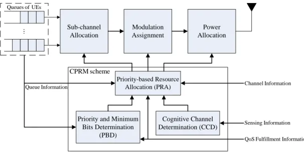
The cognitive priority-based resource management (CPRM) scheme can sense the available sub-channels from the environment, assign a suitable priority value to each UE, and then allocate the radio resource to UEs according to their priority values. Figure 3.1 shows the HeNB with the CPRM scheme. The CPRM scheme is in charge of sub-channel allocation, modulation assignment, and power allocation for HeNB. It contains three algorithms: cognitive channel determination (CCD) algorithm, priority and minimum bits determination (PBD) algorithm, and priority-based resource allocation (PRA) algorithm.
The input of the CCD algorithm is the sensing information, which is the RSS detected on each sub-channel at the last frame. According to the sensing information, the CCD algorithm determines the number of sub-frames required for HeNB to sense sub-channels and the set of available sub-channels for HeNB. The inputs of the PBD algorithm are users’ QoS fulfillment information and queue information. Based on these information, the PBD algorithm assigns a service priority value and the minimum transmission bits to each UE. Note that, the outputs from the CCD and PBD algorithms are the input of the PRA algorithm. The inputs of the PRA algorithm are the channel information, the QoS fulfillment information, the queue information, the set of available sub-channels, UEs’ priority values, and their minimum transmission bits. According to these inputs, the PRA algorithm can allocate the suitable sub-channel, modulation order, and transmission power to UEs. Details are given in the following.
21 Sub-channel Allocation Modulation Assignment Power Allocation Queues of UEs Sensing Information Queue Information
QoS Fulfillment Information Channel Information Priority-based Resource Allocation (PRA) Cognitive Channel Determination (CCD) CPRM scheme
Priority and Minimum Bits Determination
(PBD)
Figure 3.1: The HeNB with the CPRM scheme.
3.2.1 Cognitive Channel Determination Algorithm
The cognitive channel determination (CCD) algorithm determines the minimum number of sub-frames required for HeNB to sense sub-channels, and finds the available sub-channels for HeNB to avoid interfering with MeNB and its neighboring HeNBs. Let Ln be the minimum required number of sub-frames for HeNB to sense sub-channel n, which can be derived by RSSn, the pre-determined Pf, denoted by P*f , and the pre-determined Pm, denoted by Pm*. Here, the RSSn is detected at the last frame. The P*f , and P m* can be expressed by [40], [41]
* 0 2 n n th f L RSS N P Q N (3.9) and * 2 n n th m n L RSS RSS P Q R , (3.10)
22
deviation on sub-channel n in false alarm problem, R is the sensing deviation on n
sub-channel n in mis-detection problem, and Q(a) is the complementary distribution function of the standard Gaussian and is given by
2 2 1 ( ) . 2 x a Q a e dx
We rewrite (3.9) and (3.10) as 1 * 0 2 ( f) n th n Q P N RSS N L (3.11) and 1( *) 2 m n n th n Q P R RSS RSS L ,
(3.12) respectively. By adding (3.11) and (3.12), we have
1 * 1 * 0 2 ( f) n ( m) n n . n Q P N Q P R RSS N L (3.13)
Thus, the Ln can be obtained from (3.13) as
2 2 1 * 1 * 2 0 2 ( ) ( ) ( ) . ( ) n n n f m n n N R L Q P Q P RSS N N (3.14)
On the other hand, if the sub-channel n satisfies the cognitive sub-channel availability constraint of the system constraint (iii), it would be regarded as the available sub-channel. Therefore, the set of available sub-channels for HeNB, denoted by Φ, is given by
n RSSn RSSth and Ln L, 1 n N
. (3.15)
3.2.2 Priority and Minimum Bits Determination Algorithm
The priority and minimum bits determination (PBD) algorithm assigns the priority values to UEs according to their packet delay or transmission rate. It also determines the minimum transmission bits at the current frame to UEs based on the
23
QoS fulfillment information and queue information.
First, we introduce the time-to-expiration (TTE) parameter to represent the degree of urgency of UE [42]. The TTE value for UE k is denoted by Vk in unit of frames and is given by
* * , if , , if , RT k k k k k NRT k k D D k V B B D k R
(3.16)
where D k is the time duration that UE k has buffered HOL packet in the queue,
Bk is the number of residual bits of the HOL packet of UE k, and B k is the transmitted bits of UE k in Dk. The smaller the Vk is, the more urgent the UE k is. If
Vk < 0, it means the UE k violates its QoS requirement. For RT UE k, Vk is derived from its delay requirement. If Vk ≤ 1, the RT UE k is regarded as urgent, since it will violate its delay requirement and its HOL packet will be dropped after the next frames. On the other hand, for NRT UE k, Vk is derived from its minimum transmission rates; that is If Vk < 0, the NRT UE k is regarded as urgent, since it already violates its minimum transmission rate requirement.
We have the following two priority assignment rules: (i) HUE has a higher service priority than MUE.
(ii) RT UE has a higher priority value than NRT and BE UEs, while urgent NRT UE has a higher priority value than un-urgent RT UE.
Accordingly, the service priority of UE k, denoted by uk is designed as follows,
, , if , if , k f k m k u u k u u k (3.17)
where ∆uk is the priority value of each service type, and is given by *. k k k k k B B R V D
24 1 1 , if , 1 , if 0 and , 1 , if 0 and , 1 0, if , RT k NRT k k NRT k k BE k V V k u V k V k (3.18)
where ΨBE is the set of BE UEs. In (3.17), HUE k has a higher uk than MUE by u so as to satisfy the priority assignment rule (i). This can also satisfy the HUE QoS constraint of the system constraint (iv). In this thesis, the value of u is set to be 2.1, because the maximum value of ∆uk is 2. For the same service type, the smaller the Vk is, the larger the ∆uk. The ∆uk of RT UE k is set to be , which is always larger than that of un-urgent NRT UE, since the maximum value of ∆uk of un-urgent NRT UE k is 1. The ∆uk of urgent NRT UE k is set to be μ, which is between the minimum value of ∆uk for urgent RT UE k (1.5) and the maximum value of ∆uk for un-urgent RT UE k (1.3). Therefore, the priority assignment rule (ii) is satisfied. On the other hand, the ∆uk of BE UE k is set to be 0, since the BE service is the background traffic. By the design of ∆uk, the QoS fulfillment constraints (i) and (ii) can be satisfied.
The minimum number of transmission bits allocated to UE k at the current frame to avoid violating QoS requirements, γk, is given as
, if or , max{1, } min{3 , }, if and , 0, if and . k RT NRT k k e k BE f m BE B k V N B k k
(3.19)
For RT or NRT UE k, the value of γk is set to be inversely proportional to its TTE value, Vk. If UE k is urgent (Vk = 1 for RT UE and Vk < 1 for NRT UE), its HOL packet should be completely transmitted at the current frame. Because Vk of NRT UE
k may be less than 1, the denominator of γk is given by max{1,Vk}. Since BE HUE is 1 1 1 k V
25
the subscribed UE of HeNB, it should also get the service. We consider that the BE HUE should obtain at least one resource unit. Thus, the γk of BE HUE k is set to be
3Ne,which is the average transmission bits at one resource unit. Moreover, the value of γk of BE MUE k is set to be 0, since it is not the subscribed UE of HeNB.
3.2.3 Priority-based Resource Allocation Algorithm
The PRA algorithm allocates sub-channel, modulation order, and transmission power to UEs with the maximum priority value.
Let Ψc be the set of backlogged UEs with the maximum priority value, where
1max and 0, 1
.c k uk k K uk Bk k K
(3.20)
In order to achieve high system throughput and save the transmission power, the optimal pair of UE k* and sub-channel n* is selected based on the maximum SINR by
* * , ( , ) arg max c k n k n k n SINR . (3.21)
If there are multiple pairs can achieve the maximum SINR, we randomly select one pair from them. Now, the modulation order is assigned to k* based on its SINR and power budget constraint. Based on the achievable SINR between UE k* and HeNB on sub-channel n*, denoted bySINRnk**,
* *,
k n l
b is first considered to be set by
* * * * * * * * * * * * * * * * * ,2 * * ,2 ,4 , * * ,4 ,6 * ,6 0, if < , 2, if < , 4, if < , 6, if . k n k k k n k k n l k k n k k k n SINR SINR
SINR SINR SINR
b
SINR SINR SINR
SINR SINR (3.22)
If the required transmission power satisfies the power budget constraint of the system constraint (ii), the modulation order with bn lk**, is assigned to UE k
*
. Otherwise, reduce one modulation order down and check the system constraint (ii) again until
*,
F n l
26
there is no modulation order for this UE. Note that, if bn lk**, = 0, it means that there is no suitable sub-channel can be allocated to UE k*. Thus, UE k* should be removed from Ψc and its priority is set to be -1. The
k*is then updated by* * max * k*, e,0 k k bn l N .
(3.23)
Also, the B is updated by k*
* * max * k*, e,0 k k n l B B b N . (3.24)
If k* 0,the PRA algorithm will allocate the next sub-frame of sub-channel n
*
to UE
k* until k* 0 or the sub-channel n
*
has no void sub-frame.
Once the resource allocated to UE k* is completed, the CPRM scheme sets its priority value to be 0 and looks for another best pair of (k*, n*). If the sub-channel n* has no void sub-frame for data transmission, it is removed from Φ. Note that, in order to satisfy the sub-channel allocation constraint of the system constraint (i), one sub-channel is allocated to one UE at each sub-frame. If there is still the residual resource after all UEs are served (uk ≤ 0, 1 ≤ k ≤ K), the PRA algorithm sets γk = Bk, 1 ≤ k ≤ K, and redo (3.21) to allocate the residual resource to the backlogged UE with the maximum SINR. The procedure of the PRA algorithm is repeated until all radio resource is allocated to the selected UEs or no backlogged UEs exists.
3.2.4 Summary of The CPRM Scheme
Based on the CCD, PBD, and PRA algorithms, the CPRM scheme can find a sub-optimal solution for (3.8) to maximize the system throughput of HeNB, and guarantees the QoS requirements of its serving UEs. The CPRM scheme can be summarized as the following five steps.
Step 1. Initialize the CPRM scheme. Set Ln of all sub-channels by (3.14) in the CCD algorithm. Also, set uk and γk of all serving UEs by (3.17) and (3.19),
27 respectively, in the PBD algorithm.
Step 2. Find the set of the available sub-channels, Φ, by (3.15) in the CCD algorithm. Only when |Φ| > 0 and l ≤ L, the CPRM scheme would go to step 3.
Step 3. Find a pair of UE k* and sub-channel n* by (3.21) in the PRA algorithm. Then, allocate suitable and by (3.22) and (2.7), respectively, to UE k* on
sub-channel n* at the l-th sub-frame. If |Ψc| = 0, end.
Step 4. Pre-allocate the next sub-frame to the selected UE k*. If k* 0and lʹ ≤ L, set
untilk* 0.
Step 5. If |Φ| > 0 and k* 0,go to step 3. If |Φ| > 0 and uk ≤ 0, 1 ≤ k ≤ K, set γk = Bk,
1 ≤ k ≤ K, and go to step 3. If |Φ| = 0, end.
The pseudo code of the CPRM scheme is given as follows. , * * , , 1 , 1 , , 1 , and , , , , , , , , 1 . , 1 , 1 , . 1: // Initialize the CPRM scheme.
2: Set by (3.14), by (3.17), k F n n k k k k k k k k k n n l n k h k K n N RSS n N D R D R D B B BER k K b k K n N L l L L u Input : Output : and by (3.19). 3: // Find the set of available sub-channels.
4: Find by (3.15).
5: // If there is available sub-channel, perform the CPRM scheme. 6: 0 and 7: Set by (3.20). 8: // If no c k c l L while then * * * * * * , andidate UE,end. 9: 0 10: 11:
12: // Find an optimal pair of UE and sub-channel. 13: Find ( , ) by (3.21).
14: // Allocate bits and power to UE on sub-channel . 15: Set by (3 c k n l k n k n b if then break end if * * * * * * , * , 1 , , , * .22), and by (2.7). 16: // Check the system constraint (ii). 17:
18: Set 2, and by (2.7). 19:
20: // If no suitable modulation order to UE , re
F n l N F n l n k k F n l n l n l P P P b b P k while then end while * * * * * , * * * move it from . 21: 0 22: Set , = -1. 23: Go to line 7. 24: 25: Update by (3.23) and by (3.24). 26: Set 1.
27: // Pre-allocate resource to UE on sub-channel .
{ }
c k n l c c k k k b k u B l l k n if then end if * * * * * * * * * , , , 28: 0 and 29: Set , by (2.7), and 1. 30: Update by (3.23) and by (3.24). 31: 32: Update and33: // If there is residual resource and UE
k k k F n l n l n l k k k l L b b P l l B u k while then end while *
* still has the required bits, continue to
allocate the resource to the UE with the required bits. 34: 0 and 0
35: Go to line 7.
36: // If there is residual resource and all backlogged UEs
k
if then
can compete it, allocate the resource to the UE with their residual HOL packet bits.
37: 0 and == 0, 1 , 38: Set , 1 . 39: Go to line 7. 40: 41: 42: Set 1. 43: // k k k u k K B k K l l elseif then end if end while
Check whether this frame is end. 44: 45: Go to line 6. 46: lL if then end if * *, k n l b Pn lF*, * * *, *, , and *, by (2.7), 1 , k k F n l n l n l b b P l l L
28 , * * , , 1 , 1 , , 1 , and , , , , , , , , 1 . , 1 , 1 , .
1: // Initialize the CPRM scheme. 2: Set by (3.14), by (3.17) k F n n k k k k k k k k k n n l n k h k K n N RSSI n N D R D R D B B BER k K b k K n N L l L L u Input : Output : , and by (3.19). 3: // Find the set of available sub-channels.
4: Find by (3.15).
5: // If there is available sub-channel, perform the CPRM scheme.
6: 0 and 7: Set by (3.20). 8: // If no k c l L while then * * * * * * , candidate UE,end. 9: 0 10: 11:
12: // Find an optimal pair of UE and sub-channel. 13: Find ( , ) by (3.21).
14: // Allocate bits and power to UE on sub-channel . 15: Set by ( c k n l k n k n b if then break end if * * * * * * , * , 1 , , , * 3.22), and by (2.7). 16: // Check the system constraint (ii). 17:
18: Set 2, and by (2.7).
19:
20: // If no suitable modulation order to UE , r
F n l N F n l n k k F n l n l n l P P P b b P k while then end while * * * * * , * * * emove it from . 21: 0 22: Set , = -1. 23: Go to line 7. 24: 25: Update by (3.23) and by (3.24). 26: Set 1.
27: // Pre-allocate resource to UE on sub-channel
{ }
c k n l c c k k k b k u B l l k n if then end if * * * * * * * * * , , , . 28: 0 and 29: Set , by (2.7), and 1. 30: Update by (3.23) and by (3.24). 31: 32: Update and33: // If there is residual resource and UE
k k k F n l n l n l k k k l L b b P l l B u while then end while *
* still has the required bits, continue to allocate the resource to the UE with the required bits.
34: 0 and 0
35: Go to line 7.
36: // If there is residual resource and all backlogged UEs
k
k
if then
can compete it, allocate the resource to the UE with their residual HOL packet bits.
37: 0 and 0, 1 , 38: Set , 1 . 39: Go to line 7. 40: 41: k k k u k K B k K elseif then end if end while
29
Chapter 4
Simulation Results
4.1 Simulation Environment
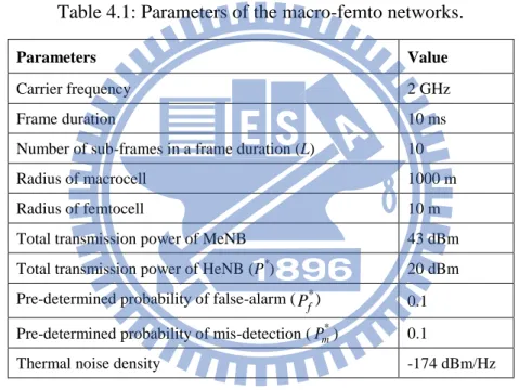
In the simulations, parameters of the considered macro-femto networks are set to be compatible with the 3GPP E-UTRA standard [36]. The parameter values are listed in Table 4.1. The system bandwidth in each sector is 5 MHz, which is divided into 25 sub-channels. Each sub-channel has 144 allocation units for data transmission. Therefore, the maximum transmission rate per macro sector is equal to 21.6 Mbps, which is obtained when each sub-channel delivers data by the highest modulation order of 64-QAM. Each sector has 3 femto blocks with the same number of deployed HeNBs of 16. The total traffic intensity (ρ) is defined as
total arrival rates of all traffics
. maximum transmission rate per macro sector
(4.1)
In each femto block, the numbers of voice, video, HTTP, and FTP UEs are set to be the same, and each HeNB is deployed with the same number of HUEs. The number of MUE is twice than that of HUE in each traffic type. Each HUE would stay in a fixed position, and each MUE would move in any direction from [-π, π) with constant speed of 3 km/hr. If total resource units in a frame duration are equally divided to HeNBs in a femto block without overlapping, then we assume every HeNB would utilize at most 15 resource units for data transmission in a frame duration. Besides, we assume that MeNB has utilized total bandwidth, and divides its total
30
transmission power fairly on the bandwidth. On the other hand, if MUE that needs service can detect the highest average SINR on bandwidth among HeNBs whose serving UE number is less than the maximum number of serving UEs, we assume the MUE would automatically hand over to that HeNB in the beginning of frame.
However, to evaluate the throughput gain from the deployment of HeNBs, we will consider the pure macro network. The pure macro network is similar to the macro-femto networks but only one difference, which is that all HeNBs are disabled and MeNB would use total bandwidth to serve all HUEs and MUEs.
Table 4.1: Parameters of the macro-femto networks.
Parameters Value
Carrier frequency 2 GHz Frame duration 10 ms Number of sub-frames in a frame duration (L) 10 Radius of macrocell 1000 m Radius of femtocell 10 m Total transmission power of MeNB 43 dBm Total transmission power of HeNB (P*) 20 dBm Pre-determined probability of false-alarm ( ) 0.1 Pre-determined probability of mis-detection (Pm*) 0.1
Thermal noise density -174 dBm/Hz
4.2 Traffic Model and QoS Requirements
Since the voice traffic is modeled as a two-state voice activity, the state update is made at the speech encoder every 20 ms with changing probability from active to inactive state of 0.1, and that from inactive to active state of 0.1. During the active period, the encoder generates a 40 bytes packet to UE every 20 ms. During the inactive period, the encoder generates a 15 bytes packet to UE every 160 ms. Thus, the arrival rate of voice traffic is 8.375 Kbps.
In the video traffic, the video frame arrives every 100 ms, and contains 8 packets, *
f
31
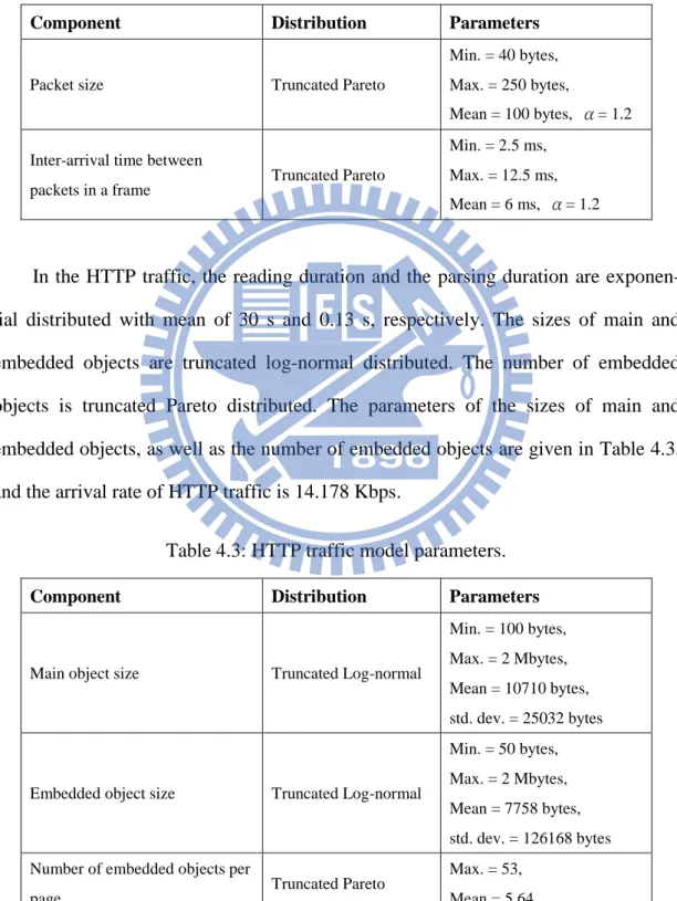
while the size of packet and the inter-arrival time between packets are both truncated Pareto distributed. The parameters of the size of packet and the inter-arrival time are given in Table 4.2, and the arrival rate of video traffic is 64 Kbps.
Table 4.2: Video traffic model parameters.
Component Distribution Parameters
Packet size Truncated Pareto
Min. = 40 bytes, Max. = 250 bytes, Mean = 100 bytes, α= 1.2 Inter-arrival time between
packets in a frame Truncated Pareto
Min. = 2.5 ms, Max. = 12.5 ms, Mean = 6 ms, α= 1.2
In the HTTP traffic, the reading duration and the parsing duration are exponen- tial distributed with mean of 30 s and 0.13 s, respectively. The sizes of main and embedded objects are truncated log-normal distributed. The number of embedded objects is truncated Pareto distributed. The parameters of the sizes of main and embedded objects, as well as the number of embedded objects are given in Table 4.3, and the arrival rate of HTTP traffic is 14.178 Kbps.
Table 4.3: HTTP traffic model parameters.
Component Distribution Parameters
Main object size Truncated Log-normal
Min. = 100 bytes, Max. = 2 Mbytes, Mean = 10710 bytes, std. dev. = 25032 bytes
Embedded object size Truncated Log-normal
Min. = 50 bytes, Max. = 2 Mbytes, Mean = 7758 bytes, std. dev. = 126168 bytes Number of embedded objects per
page Truncated Pareto
Max. = 53, Mean = 5.64
32
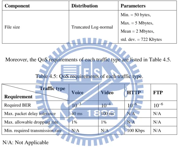
In the FTP traffic, the FTP file size is truncated log-normal distributed, and the inter-arrival time between two successive files is exponential distributed with mean of 180 s. The parameters of the file size are given in Table 4.4, and the arrival rate of FTP traffic is 88.89 Kbps.
Table 4.4: FTP traffic model parameters.
Component Distribution Parameters
File size Truncated Log-normal
Min. = 50 bytes, Max. = 5 Mbytes, Mean = 2 Mbytes, std. dev. = 722 Kbytes
Moreover, the QoS requirements of each traffic type are listed in Table 4.5. Table 4.5: QoS requirements of each traffic type.
Traffic type
Requirement Voice Video HTTP FTP
Required BER 103 104 106 106 Max. packet delay tolerance 40 ms 100 ms N/A N/A Max. allowable dropping rate 1% 1% N/A N/A Min. required transmission rate N/A N/A 100 Kbps N/A
N/A: Not Applicable
4.3 Conventional Schemes
In the simulations, we would compare the proposed CPRM scheme with two conventional schemes, which are decomposion-based resource management (DBRM) scheme [43] and cognitive radio resource management (CRRM) scheme [44]. Both the DBRM and CRRM schemes are representative schemes for cognitive femtocell, and the details of these two schemes are given in the following.
33
4.3.1 Decomposition-based Resource Management Scheme
The HeNB would sense one sub-frame to indicate the set of available sub-channels in the beginning of frame, and then performs the DBRM scheme. The DBRM scheme aims to maximize the throughput of HeNB by employing the decomposition methods. It decomposes the resource allocation problem into master problem for channel allocation, and sub-problem for power allocation. The channel allocation on sub-channel c of HeNB i to UE j is based on the gijc, which is defined as
0 , ijc ijc ijc h g I N (4.2) where hijc (Iijc) is the channel gain (sensed interference) between HeNB i to UE j on sub-channel c. HeNB i would allocate an available sub-channel c* to UE j*, if gij c* * has the maximum value. Then, remove sub-channel c* and UE j* from its set of available sub-channels and UEs, and then repeat the channel and UE allocation until there is no sub-channel or UE left.
Based on the channel allocation result, HeNB i would determine the transmission power to UE j on sub- channel c by
* * 1 1 1 1 1 , k ijc P ijc k K ikc ijc P P P K K g g
(4.3)
where ck is the allocated channel to UE k, and Pijc is the minimum required power for HeNB i to achieve the minimum required SINR for UE j on sub-channel c. Because the DBRM scheme only consider the channel condition between HeNB and UE, it would treat HUE and MUE in the same manner. Furthermore, there are four traffic types in the network, and each traffic type has different QoS requirements. To make a fair comparison, we would allocate resource to urgent UE first in the DBRM scheme so as to guarantee the QoS requirements of UEs.