Abstract—Highlights of the recent development of highly ef-ficient and robust blue fluorescent organic light-emitting device (OLED) materials and devices are reviewed with emphasis on work accomplished at the OLED Laboratory of Display Institute, National Chiao Tung University, Hsinchu, Taiwan, R.O.C.
Index Terms—Blue dopant, blue fluorescent materials and de-vices, electroluminescence, organic light-emitting diode (OLED).
I. INTRODUCTION
O
RGANIC light-emitting devices (OLEDs) have received considerable attention due to their superb display image quality and demonstrated manufacturing and market potentials in small-to-medium mobile display applications. As a result, burgeoning commercialization activities are well underway. However, before OLED can become one of the mainstream display technologies living up to its full potential and com-peting effectively with liquid crystal display (LCD), a number of material and device stability-related issues must be resolved, of which the blue emitter is perhaps one of the most critical.For full-color OLED display applications, it is essential to deliver a set of primary RGB emitters with sufficiently high luminous efficiency, properly balanced color chromaticity, as well as sufficient operational stability. Such a set of emitters has been amply demonstrated by using a guest-host doped emitting system which encompasses a single or cohost matrix dispersed with various highly fluorescent or phosphorescent guest dopants leading to electroluminescence (EL) with the desirable hues [1]. With the discovery and rapid improvement of phosphorescent dopant materials along with their matching host, hole-blocker and device architecture capable of harvesting both the singlet and triplet excitons electrogenerated in the doped emitter, in today’s OLEDs, to achieve high efficiency and color saturation for the red and green emitters is no longer a major problem. The
Manuscript received March 2, 2005; revised May 20, 2005. This work was supported in part by the MOE Program for Promoting Academic Excellence of Universities under Grant 91-E-FA04-2-4-B and by a research grant from the In-dustry/Academia Joint Development Project provided by e-Ray Optoelectronics Technology Co., Ltd., of Taiwan.
S.-W. Wen and M.-T. Lee are with the Department of Applied Chemistry, National Chiao Tung University, Hsinchu 30050, Taiwan, R.O.C.
C. H. Chen is with the Display Institute, Microelectronics & Information Sys-tems Research Center, National Chiao Tung University, Hsinchu 30050, Taiwan, R.O.C. (e-mail: [email protected]).
Digital Object Identifier 10.1109/JDT.2005.852802
decision by Pioneer in 2003 announcing the use of one of United Display Corporation’s (UDC) red phosphorescent dopants cou-pled with a BAlq-based host material in its new 1.1-in pas-sive matrix 96 RGB 72 full-color subdisplay cellular phone has all but removed the last skepticism hanging over the in-trinsic stability issue of phosphorescent materials worthy of pro-duction [2]. Similar improvement of extremely efficient green phosphorescent devices ( 40 cd/A) with operational stability of 20 000 h at an initial luminance of 1000 cd/cm and a 1931 Commission Internationale de L’Eclairage close to (0.31, 0.64) has also been disclosed by many which include UDC [3], Chi Mei [4], Covion [5], [33], and Canon [6]. It is ex-pected that, in the future, we would also find one of these green phosphorescent materials ending up in some forms of OLED products in the marketplace.
Unfortunately, the same cannot be said for the state of the art of the phosphorescent blue emitter which remains to be the weakest link in the development of RGB phosphorescent materials. To date, the best triplet blue emitter reported with limited lifetime is due to UDC [7] which claimed to have achieved a luminous efficiency of about 30 cd/A at 100 cd/m with a sky blue (0.16, 0.38) and a lifetime of only
2000 h. A slightly deeper blue emitter of (0.14, 0.21) disclosed recently fairs no better with 19 cd/A at 100 cd/m and a similar dismal lifetime. Very recently, at the International Display Manufacturing Conference (IDMC) 2005, held in Taipei, Taiwan, Samsung SDI managed to disclose for the first time [8] a deep blue phosphorescent emitter with (0.15, 0.15) but only can last for 150 h. Part of the problems in producing a decent saturated blue phosphorescent emitter with lies in the fact that there is simply no good host material available that possesses sufficiently large triplet bandgap energy ( 3 eV) to effectively prevent triplet exciton of the dopant from quenching by back energy transfer, and the limitation of short-conjugated ligand selection for synthesizing transition metal-based metal–ligand charge-transfer (MLCT) complexes serves only to compound the already grave and aggravated situation [9]. All things considered, it suffices to predict that, in the foreseeable future, the advent of a robust phosphorescent blue emitter with all of the necessary attributes for high efficiency, saturated color, as well as device stability would be extremely difficult. In all likelihood, we will see the future high-resolution AM-OLED full color display products including the coveted TFT-OLED TVs, continue to be hybrid 1551-319X/$20.00 © 2005 IEEE
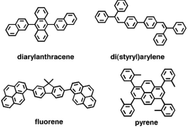
Fig. 1. Representative blue host materials.
and in need of blue fluorescent materials for a long time to come.
It is mainly for this reason that we have been focusing on the research and development of stable blue fluorescent materials and devices at the OLED laboratory of the Display Institute of National Chiao Tung University (NCTU), Taiwan, including the deep blue emitter which is defined arbitrarily as having a blue EL emission with . This review will account and summarize what has been discovered at NCTU in the last several years concerning the development of highly efficient and stable blue fluorescent emitters suitable for use in future high-resolu-tion full-color RGB OLED displays. We will, when appropriate and applicable, cite related blue fluorescent dopant/host mate-rials and device structures in the art and also compare our device performance with the best of what has been published in the lit-erature.
II. INSERARCH OF AROBUSTBLUEHOSTMATERIAL There are a number of stable blue host materials that have been disclosed in the literature which can be roughly cat-egorized into several major classes of compounds, namely, diarylanthracene [10], di(styryl)arylene (DSA) [11], fluorene [12], and pyrene [13] whose representative structures and cor-responding acronyms are shown in Fig. 1. Unfortunately, not all detailed information about these host molecules are known however, as most of these compounds remain trade secrets by the companies who invented them and tend to guard them from full disclosure even after years of having been granted intellectual rights and patent protection. Some tend to release only their best device performance without any reference to chemical structures which are often represented by mere catalog numbers. Others will show part of a general structure but choose only to publish their best EL performance without having anything to do with the structures that were attached in the paper. The worst are those who deceptively disclosed the wrong structure to mislead and misinform the public. The upside is that one sees that OLED performance is breaking new ground and making progress almost every other month. How-ever, for the OLED scientific community, the long-term effect is that most of these exorbitant claims and results cannot be independently verified which makes any further improvement
Fig. 2. Structures of modified blue host based on ADN.
extremely difficult, if not impossible. One wonders whether this tactic is helping to promote and grow the OLED technology or actually hampering it.
A. Diarylanthracenes
We made a conscientious decision to follow up the work published by Shi and Tang at Kodak [10], who in 2002 re-ported that 2, 5, 8, 11- ( -butyl)perylene (TBP) doped in 9, 10- (2-naphthyl)anthracene (ADN) as blue emitter in the device structure of [ITO/copper phthalocyanine (CuPc) (25 nm)/4,4 - [ -(1-naphthyl)- -phenyl-amino] biphenyl (NPB) (50 nm)/ADN:TBP (30 nm)/ aluminum (8-hydrox-yquinoline) Alq (40 nm)/Mg:Ag (9:1, 200 nm)] was very stable and had achieved a luminance efficiency of 3.5 cd/A with coordinates of (0.15, 0.23). The device operational life-time reported was about 4000 h with an initial luminance of 636 cd/m that was one of the best ever published in a formal journal at that time.
Thus, we made further study of ADN as blue host mate-rial which revealed that its thin-film morphology is rather un-stable and tends to deteriorate under prolonged electrical stress or annealing at elevated temperatures (95 C), and its color is also a little too green [14]. Subsequently, in attempts to im-prove the emissive color, the tert-butyl substituted derivative, 2-( -butyl)-9,10- (2-naphthyl)anthracene (TBADN), was de-scribed by the Kodak group in a European patent [15]. Using the same dopant and device configuration, TBADN was able to generate a somewhat deeper blue emission of (0.13, 0.19), but its efficiency was considerably lower, and unfortu-nately there was disclosed neither morphological nor device sta-bility data.
In an effort to improve the thin-film morphological stability of ADN by molecular engineering, several multi- -butyl-substi-tuted ADN derivatives, such as 2,6- ( -butyl)-9,10- (2-naph-thyl)anthracene (DTBADN) and 2,6- ( -butyl)-9,10-[6-( -butyl)-2-naphthyl]anthracene (TTBADN) were synthe-sized and compared with ADN and TBADN (Fig. 2). It was discovered however, by virtue of its inductive effect, that the -butyl groups could cause significant bathochromic shift of ADN’s fluorescence in both of these derivatives and lower its photoluminescent quantum efficiency as well. It was also suggested that the greenish color and low EL efficiency of DTBADN and TTBADN could be due to the bulky -butyl
Fig. 3. AFM images of (a) ADN and (b) MADN after annealing at 95 C for 1 h.
TABLE I
PLANDTHERMALPROPERTIES OFADN DERIVATIVES
groups which tend to twist the chromophore of ADN as re-vealed by computer simulations using the Quantum CAChe (v. 5.02) program. Recently, we have also found that the bulky -butyl substitution on ADN-based films could also signifi-cantly impact on their carrier mobility [16].
In order to enhance the thin-film morphological stability of ADN without adversely effecting its EL emission, efficiency and charge-carrier mobility, we began a systematic study of alkyl substitution on the 2-position of ADN. It was found that the best way to stabilize the morphology of ADN was to strate-gically place a relatively small methyl-group at C-2 position of the anthracene moiety—i.e. 2-methyl-9,10- (2-napthyl)an-thracene (MADN) which can readily be synthesized by Suzuki coupling of the 2-methyl-9,10-dibromo-anthracene with 2-(napthyl)boronic acid according to a known procedure [17]. By computer simulation, we find that the symmetry and close molecular packing of ADN is disrupted by the methyl substituent in the space group which results in the increase of the intermolecular distance. As a result, the thin-film surface morphology of MADN is considerably more robust than that of ADN as revealed by the AFM photographs before and after annealing (Fig. 3). The small methyl substituent seems to have little effect on the LUMO/HOMO level of ADN which remains at 2.5/5.5 eV with a bandgap energy of 3 eV. Table I shows the comparison of solution PLs of various substituted ADN derivatives in toluene along with its thermal properties. In comparison with their solution PL fluorescence and relative quantum efficiency in toluene, both MADN and TBADN have better efficiency than those of ADN. Low-temperature PL studies revealed also that both MADN and TBADN have different vibronic levels which shift their luminescence peaks
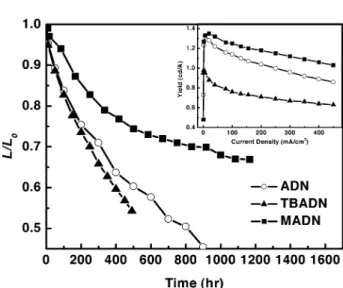
Fig. 4. Device stability and EL efficiency comparison of ADN, TBADN, and MADN.
significantly enough that their CIE color coordinates move to deep blue and therefore have potential for deep blue OLED application [18].
Comparison of their EL performance in
a microcavity optimized device structure of
ITO/CF NPB nm blue nm Alq nm
LiF nm Al nm showed MADN had the best luminous efficiency of 1.4 cd/A and the lowest drive voltage of 6.2 V (measured at 20 mA/cm ) with also the bluest color of (0.15, 0.10) that is identical to that of TBADN, as shown in the inset of Fig. 4. Device stability data of all three nondoped devices depicted in Fig. 4 confirmed that MADN indeed stands out as the best in the diarylanthracene-type of blue hosts with a projected lifetime of about 7000 h at an initial luminance of 100 cd/m which is nearly 7 and 3 longer than those of TBADN and ADN, respectively.
B. Di(styryl)Arylenes
Another famous blue host material known as DPVBi in the OLED community was first published by Hosokawa and coworkers at Idemitsu [11]. The key to its molecular design is the terminally substituted (phenyl)styryl group which is sup-posed to lock the styryl-conjugated chromophore in the planar conformation by twisting the extra bulky phenyl group out
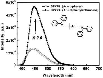
Fig. 5. Structures and PL spectra of DPVBi versus DPVPA.
of the plane assumed by the (phenyl)styrene chromophore. It has a LUMO/HOMO level of near 2.8/5.9 eV with a wide bandgap energy of 3.1 eV, which is similar to that of the ADN series. The structure that was released subsequently in all of their papers with excellent EL performance [11] had a biphenyl core, as shown in Fig. 5. However, on further scrutiny, it became increasingly clear that the DPVBi as disclosed could not have been a good blue host material since it has a relative quantum efficiency in toluene of only about 38%, which is too low for efficient Förster energy transfer. One can only guess what the authors’ intentions were in disclosing the wrong structure in relation to the best device EL performance that was claimed at that time. The clue to the true identity of this well-disguised blue host was not revealed until only recently when, at the SID 2004 (International Conference of Society for Information Display, 2004) [19], the structure (here abbreviated as DPVPA) in which the center biphenyl core of DPVBi has been replaced by the diphenylanthracene was reported in an oral presentation, albeit it was purely unintentional. We, along with other laboratories, began to look into DPVPA earnestly as a potential robust blue host material [20] to be compared with MADN. Indeed, it was quickly found that the quantum efficiency is about 2.6 times better than that of DPVBi and a solution (toluene) fluorescence of 448 nm, which is also about 20 nm green shifted due to the relatively longer conjugation (Fig. 5).
In EL performance as an undoped device using the same
structure of ITO CF NPB nm nm
Alq nm LiF nm Al nm , we found that DPVPA with an external quantum efficiency (EQE) of 3% is more efficient than MADN (EQE 1.5%) but its color appears greener with a (0.14, 0.17). The detailed comparison of their EL performances are made in Table II, in which we find that the drive voltage of MADN is about 20% lower than that of DPVPA, which suggests that the carrier transport prop-erty of MADN is much better as revealed in the – curve shown in Fig. 6. In terms of device stability, the extrapolated lifetime of MADN of 7000 h at a normalized luminance of cd/m is actually better than that of DPVPA with 5600 h.
Fig. 6. Device stability (at a constant dc drive of 20 mA/cm ) andJ–V comparison of MADN versus DPVPA.
III. SKYBLUEDOPANTMATERIALS ANDDEVICES Since the stability and color saturation of blue fluorescent OLEDs are two of the most critical concerns of today, we felt in many ways, as described in the last section, that the MADN as a host material is better than DPVPA even though its luminance efficiency is lower. However, that should pose no problem as, with its wide bandgap energy and greater operational stability, the enhancement of EL efficiency can be readily realized with the judicious selection of a matching dopant for efficient Förster energy transfer.
A. Tetra(t-butyl)Perylene (TBP)
In terms of structure, one of the most stable blue dopants is TBP, as it contains no functional group that is chemically, ther-mally, or photolytically sensitive (Fig. 7). Consequently, TBP was the first blue dopant used by Kodak to provide high effi-ciency and device stability [10]. Unfortunately, because of its rigidity and planarity, TBP having a small Stoke shift can only produce a sky-blue emission, which appears to be also easily subjected to concentration quenching. As shown in Table II, the best device performance obtained by doping 0.5%v/v in MADN
Fig. 7. Structures of typical sky-blue dopants.
Fig. 8. Solution PLs of MADN and DPVPA overlaid with the absorption of DSA-Ph.
was 3.4 cd/A at 20 mA/cm and 6.3 V with a (0.13, 0.20). Even though the stability of TBP-doped MADN devices are great at of about 5000 h with an initial luminance of 680 cd/m , the lack of functional group on perylene makes it almost impossible to change the chromophore and tune its emis-sive color at will.
B. Diphenylamino-di(styryl)Arylene(DSA-Ph)
The other stable sky-blue dopant whose structure was re-cently published by Suzuki and coworkers of Canon [21] is known as IDE-102. In this paper, it is reported to have a (di-p-toyl)aminostyrene with a biphenyl core structure, as shown in Fig. 7. Chromophores of this type of structure are particularly easy to manipulate by molecular engineering either via change in the (aryl)aminostyryl end of the structure or via change of the center core. Bits and pieces of information regarding the EL performance of this dopant have been disclosed by Hosokawa and coworkers at Idemitsu in the past, but never with a structure [22].
We chose to work with a similar but much simpler dopant of the structure of (diphenyl)aminostyryl benzene [23] hitherto abbreviated as DSA-Ph, as shown in Fig. 7. It has an absorp-tion of 410 nm and a fluorescence of 458 nm with FWHM of 54 nm and a LUMO/HOMO level of 2.7/5.4 eV with a bandgap energy of 2.7 eV. In Fig. 8, the solution (toluene) ab-sorption and fluorescence spectra of DSA-Ph are overlaid with
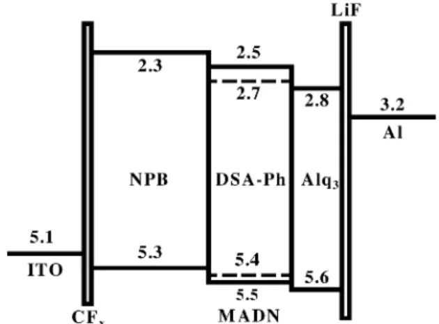
Fig. 9. Energy diagram of a DSA-Ph doped MADN blue OLED.
Fig. 10. Device stability and luminance efficiency-J of DPVPA versus MADN with 3% DSA-Ph dopant.
the fluorescence spectra of host MADN and DPVPA. We found there is greater overlap for more efficient Förster energy transfer in MADN than in DPVPA.
In our standard blue device structure as described earlier, 3% DSA-Ph doped in MADN achieved a luminance efficiency of 9.7 cd/A and 5.5 lm/W at 20 mA/cm and 5.7 V with a (0.16, 0.32) while in DPVPA, it yielded 10.2 cd/A and 4.8 lm/W at 6.7 V with a (0.16, 0.35) as shown in Table II. The better transport property of host MADN molecules than that of DPVPA is evident as reflected in its much lowered drive voltage by nearly 1 V. From the energy diagram shown in Fig. 9, the DSA-Ph dopant can effectively provide an energetically favorable pathway for both e and h transported into the emitter for recombination [24]. DSA-Ph doped in MADN also greatly suppressed the current-induced quenching, as shown in Fig. 10, in which the device stability measured at a constant dc drive of 20 mA/cm is also compared with that of DPVPA. The stability of the 3% DSA-Ph doped MADN device is expected to last 46 000 h at cd/m .
We also disclosed in IDMC 2005 that the efficiency of this sky-blue emitter could be enhanced further by in-troducing a composite hole transport layer
made of CuPc and NPB in the multilayered structure of
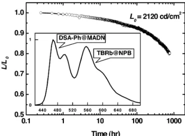
Fig. 11. White OLED based on DSA-Ph doped MADN and TBRb.
Fig. 12. Stability and EL spectra of white OLED.
This new emitter has achieved EL efficiency of 16.2 cd/A and 7.86 lm/W with a (0.15, 0.29) at 6.4 V (20 mA/cm ) and an EQE of 8.7%, which is to our knowledge one of the best ever reported for the fluorescent sky-blue emitters in OLEDs [25]. C. Development of White OLED
Recently, the white OLED coupled with an RGB color filter has become increasingly popular as one of the major method-ologies for fabricating high-resolution full-color devices [26]. This is primarily due to cost and mass production considerations as the discreet RGB pixelation process can be accomplished without the use of tedious and troublesome shadow masks. One of the key elements in many of today’s white OLED compo-sitions is a highly efficient and robust sky-blue emitter which can be coupled with a yellow or orange emitter to form the white light additively. In NCTU, we used a sterically hindered yellow dopant, 2,8- ( -butyl)-5,11- [4-( -butyl)phenyl]-6,12-diphenylnaphthacene (TBRb) in NPB to compose the two-el-ement white OLED with the stable sky-blue emitter DSA-Ph doped in MADN (Fig. 11) from which an EL efficiency of 12.8 cd/A and 4.3 lm/W at 20 mA/cm with (0.31, 0.38) was obtained [27]. The EL spectra of this white emission and its de-vice operational stability at constant dc drive at 20 mA/cm are shown in Fig. 12. The stability of this white OLED is 3000 h with cd/m which is estimated to last more than
60 000 h at .
Fig. 13. Power consumption versus blue CIE color coordinate.
Fig. 14. Solution PLs of deep blue dopants versus DSA-Ph. IV. DEEPBLUEDOPANTMATERIALS ANDDEVICE Besides the sky-blue emitter, it is also highly desirable to develop organic EL that emits in the deep blue region [28], since such an emitter can reduce the power consumption of a full-color OLED and can be utilized to generate light of other colors by energy cascading to a suitable emissive dopant. Fig. 13 shows a plot of blue color coordinate versus power con-sumption in the composition of white balance in a full-color OLED in which substantial savings of power can be obtained if the blue emitter has a deep blue emission with . A. Deep Blue Dopant Material Engineering
Since hypsochromically shifting TBP’s emission is very diffi-cult, we instead modify the basic DSA-Ph chromophore in order to turn its color to deeper blue. Besides, DSA-Ph-doped devices have been shown to be more efficient and just as stable as those of TBP in MADN. From the material design and synthetic point of view, the most straightforward solution is to shorten the con-jugation length (chromophore) of the di(styryl)benzene-based dopant to the mono-styrylbenzene-based core, as represented by the general structure shown in Fig. 14. By modifying the sub-stituents attached to the nitrogen ( and ) as well as to the styrene ( and ), it is possible to optimize the structure to
Fig. 15. EL spectral comparison of BD-1 doped and undoped MADN devices. achieve various desirable emissions in the deeper blue region of the visible spectrum. This is exemplified in the solution PLs of BD-1, BD-2, and BD-3 in toluene as compared with DSA-Ph in Fig. 14. Their spectroscopic properties are summarized in Table III. Their peak fluorescence is all within the range of 430–450 nm and the FWHM are around 60 nm, which is about 20 nm blue-shifted from that of the sky blue dopant, DSA-Ph. The hypsochromic shift is the result of molecular engineering by tuning the chromophoric conjugation length as well as mod-ifying the aromatic substituents of the amine-based dopant.
Fig. 15 shows the EL spectra of the undoped and BD-1 doped MADN devices (driven at 20 mA/cm ). The spectra of undoped and BD-1 doped devices exhibit one dominant peak at 440 nm with a full-width at half-maximum (FWHM) of 56 nm and 452 nm with a FWHM of 60 nm, respectively. The coordi-nates of the BD-1 doped MADN devices is (0.15, 0.11). At the optimal doping concentration of 3%, BD-1 device achieved an EL efficiency of 2.2 cd/A at 20 mA/cm and 6.1 V with an EQE of 2.3%.
B. Deep Blue Device With Hole-Blocking Layer (HBL) Fig. 16 shows the comparison of luminance–current den-sity–voltage (B–I–V) characteristics of the BD-1 doped device with and without 2,9-dimethyl-4,7-diphenyl-1,10-phenanthro-line (BCP) as hole blocking layer (HBL) interposed between the emissive layer (EML) and Alq . We discovered that the EL efficiency of the device with HBL (driven at 20 mA/cm ) could be significantly enhanced as much as 100% as compared to that of the conventional device [29]. The coordinates of the BD-1 doped MADN devices with BCP is (0.15, 0.13). At
Fig. 16. J–V comparison of BD-1 doped MADN devices with and without the BCP hole-blocker.
TABLE IV
EL PERFORMANCE OFDOPEDDEEPBLUEDEVICESWITHHBL
an optimal concentration of 7% doping, BD-1 device achieved an EL efficiency of 3.9 cd/A and 2.0 lm/W at 20 mA/cm and 6.2 V. We attribute the dramatic increase in efficiency to the formation of a narrow recombination zone, in which both charge carriers and exciton are confined [30]. In addition, it is worth noting that, when BCP is used as the HBL in most other devices reported in the literature, the driving voltage is often increased. This phenomenon has been rationalized by the poor electron mobility of BCP that is lower than that of Alq [31]. But, in our experiment, the – characteristics of both device configurations (with and without HBL) were essentially iden-tical. We attribute this result to the characteristic amine-based dopant, which has a high hole-transporting mobility [27] and a low ionization energy potential that lies in between those of NPB and MADN. As a result, it provides a more effective pathway for the hole to inject directly from NPB to the dopant for recombination rather than from NPB to host MADN followed by exciton energy transfer. Consequently, the low electron mobility of BCP will not significantly impact on the drive voltage of this device under this model, which also partially explains why we need an unusually high concentration (7%) of BD-1 to get the best EL performance.
The other deep blue dopants, BD-2 and BD-3 doped MADN devices, were also fabricated accordingly. The detailed EL per-formances are summarized in Table IV. The voltage, luminance yields, color coordinates, and power efficiencies were measured at 20 mA/cm . The EL efficiency of BD-2 and BD-3 doped de-vices were 5.1 and 5.6 cd/A with color coordinate of
Fig. 17. Structures of BD-1 doped MADN deep blue devices with and without c-HTL.
Fig. 18. J–V dependence of devices with and without c-HTL.
(0.14, 0.16) and (0.14, 0.17), respectively. Their maximum EQE of 4.2% is close to the theoretical limit of fluorescence-based OLEDs of today.
C. Deep Blue Device With a Composite Hole-Transport Layer ( -HTL)
Another way to enhance the EL efficiency of the deep blue fluorescent device developed at NCTU is to better balance the h-and e-carriers arriving at the recombination zone. This is accom-plished by inserting a composite hole-transport layer ( -HTL) made of CuPc and NPB in between the hole injection layer of
and the HTL of NPB to which we alluded earlier. In our study, two blue devices have been fabricated. Device I is a standard blue device. Device II is the blue device incor-porating the -HTL. Detailed device architectures are shown in Fig. 17, where CF is the hole-injection layer, -HTL and NPB as a whole are the hole transport layer, BD-1 doped MADN is the blue emitter, Alq is the electron transport layer, and LiF/Al is the cathode. Fig. 18 shows the – curves of these blue de-vices. A higher operating voltage was observed in the device with -HTL compared to that of the standard device, which is attributed to the “hole-impedance” of CuPc.
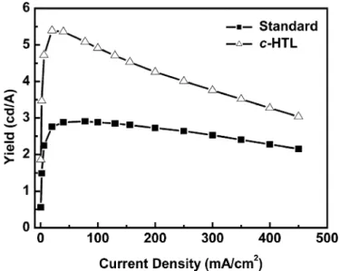
Fig. 19 shows the plot of luminance yield versus current den-sity of these blue devices. The dramatic enhancement in lumi-nance yield by incorporating -HTL or HBL is believed to result
Fig. 19. Plots of luminance yield versusJ of devices with and without c-HTL. TABLE V
OVERALLEL PERFORMANCE OFBD-1 DOPEDMADN DEVICES
from better carrier recombination at the emitting zone. How-ever, the mechanisms are different in each case. In the case of HBL, holes are accumulated at the EML/HBL interface, which gives rise to a narrow recombination zone, whereas in the case of -HTL the hole transport was reduced, which results in the for-mation of a recombination zone that can be much broader and diffused. A broad emission zone is likely to have a beneficial ef-fect on luminance efficiency since the probability of quenching of the singlet excited states by polarons would be reduced [32]. The overall EL performances of these blue devices are sum-marized in Table V. Compared with the luminous efficiency of the blue device with HBL (4.1 cd/A), the blue device with -HTL has been improved to 5.4 cd/A with a coordi-nates of (0.14, 0.13) and a power efficiency of 2.5 lm/W and EQE of 5.1% (20 mA/cm ) at 6.8 V.
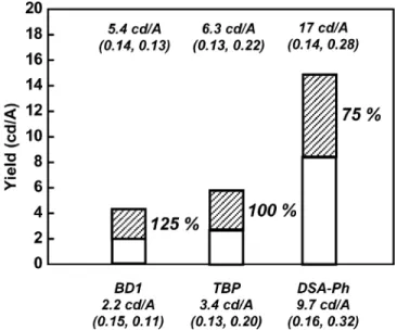
Fig. 20 summarizes the advantage of incorporating the -HTL in the doped blue devices studied in this paper in terms of overall luminance efficiency gain, namely, BD-1, TBP, and DSA-Ph-doped MADN blue OLED devices. The overall performance of NCTU’s doped blue emitters, which includes efficiency, life-time, and , are benchmarked against the best reported data by Idemitsu, Kodak, and Canon in Fig. 21.
V. CONCLUSION
This paper reviews some of the recent development of highly efficient and stable blue fluorescent dopant materials and de-vices with emphasis on research accomplished at the OLED
Fig. 20. Summary of NCTU’s recent blue OLED development.
Fig. 21. State of the art of highly efficient and stable blue emitters reported to date.
Laboratory of the Display Institute at NCTU in the last few years. For full-color OLED applications, it is critical to consider not only efficiency and device stability, but also the color. To achieve maximum overall performance, it is necessary to use the “system approach” in optimizing not only the emissive layer but also the device architecture, in which many layers are of equal importance and play a complementary role. Judging by the state of the art of blue fluorescent materials and device highlighted in this paper, we believe it is now ripe for full-color OLEDs to move into the next phase of commercialization in which the blue fluorescent emitter could play a key role in its success in the marketplace in the foreseeable future.
ACKNOWLEDGMENT
The authors would like to thank Y.-S. Wu, C.-M. Chang, C.-M. Yeh, C.-H. Tsai, and C.-H. Liao of the Department of Applied Chemistry, NCTU, for providing support with the syn-thesis, literature search, and device fabrication. The generous supply of OLED materials provided by e-Ray Optoelectronics,
“High efficiency and long lifetime phosphorescent OLEDs,” in Proc.
Int. Conf. Electroluminescence of Molecular Materials and Related Phe-nomena, Jejn Island, Korea, 2003, p. O-35.
[4] J.-W. Chung, H.-R. Guo, C.-T. Wu, K.-C. Wang, W.-J. Hsieh, T.-M. Wu, and C.-T. Chung, “Long-operating lifetime of green phosphorescence top-emitting organic light emitting devices,” in Proc. Int. Display
Man-ufacturing Conf., Taipei, Taiwan, 2005, pp. 278–280.
[5] H. Becker, H. Vestweber, A. Gerhard, P. Stoessel, and R. Fortte, “Novel host materials for efficient and stable phosphorescent OLED devices,” in Proc. Int. Display Manufacturing Conf., Taipei, Taiwan, 2005, pp. 329–330.
[6] K. Okinaka, A. Saitoh, T. Kawai, A. Senoo, and K. Ueno, “High-per-formable green-emitting OLEDs,” in Proc. Soc. Information Display, Seattle, WA, 2004, pp. 686–689.
[7] M. Heck and J. J. Brown, “OLED excitement,” Inf. Display, vol. 20, no. 6, pp. 12–17, 2004.
[8] J. Y. Lee and J. H. Kwon, “Performance improvement of active matrix light emitting diodes,” in Proc. Int. Display Manufacturing Conf., Taipei, Taiwan, 2005, pp. 329–330.
[9] S.-J. Yeh, M.-F. Wu, C.-T. Chen, Y.-H. Song, Y. Chi, M.-H. Ho, S.-F. Hsu, and C. H. Chen, “New dopant and host materials for blue-light-emitting phosphorescent organic electroluminescent de-vices,” Adv. Mater., vol. 17, no. 3, pp. 285–289, 2005.
[10] J. Shi and C. W. Tang, “Anthracene derivatives for stable blue-emittin-gorganic electroluminescence devices,” Appl. Phys. Lett., vol. 80, no. 17, pp. 3201–3203, 2002.
[11] C. Hosokawa, H. Higashi, H. Nakamura, and T. Kusumoto, “Highly ef-ficient blue electroluminescence from a distyrylene emitting layer with a new dopant,” Appl. Phys. Lett., vol. 67, no. 26, pp. 3853–3855, 1995. [12] A. Saitoh, N. Yamada, M. Yashima, K. Okinaka, A. Senoo, K. Ueno, D. Tanaka, and R. Yashiro, “Novel fluroene-based blue emitters for high oerformance OLEDs,” in Proc. Soc. Information Display, Seattle, WA, 2004, pp. 150–153.
[13] C. C. Yeh, M. T. Lee, H. H. Chen, and C. H. Chen, “High-performance blue OLEDs based on sterically hindered pyrene host material,” in Proc.
Soc. Information Display, Seattle, WA, 2004, pp. 788–792.
[14] W. J. Shen, B. Banumathy, H. H. Chen, and C. H. Chen, “Sterically hindered blue host emitters based on anthracene,” in Proc. Int. Display
Manufacturing Conf., Taipei, Taiwan, 2003, pp. 741–743.
[15] J. Shi, “Method of Using Predoped Materials for Making an Organic Light-Emitting Device,” Eur. Patent 1 156 536, Nov. 21, 2001. [16] S. K. So, S. C. Tse, H. H. Fong, and C. H. Chen, “Charge conduction
in fused aromatec compounds for OLED’s applications,” in Proc. Int.
Display Manufacturing Conf., Taipei, Taiwan, 2005, pp. 275–277.
[17] M. T. Lee, Y. S. Wu, H. H. Chen, C. T. Tsai, C. H. Liao, and C. H. Chen, “Efficient blue organic electroluminescent devices based on a stable blue host material,” in Proc. Soc. Information Display, Seattle, WA, 2004, pp. 710–714.
[18] K. F. Li, K. W. Cheah, K.-T. Yeung, Y.-K. Cheng, Y.-S. Wu, and C. H. Chen, “Emission characteristics of ADN derivatives,” in Proc. Int.
Display Manufacturing Conf., Taipei, Taiwan, 2005, pp. 136–138.
[19] T. A. Ali, G. W. Jones, and W. E. Howard, “Dual doped high Tg white organic light emitting devices on silicon,” Proc. Soc. Information
Dis-play, pp. 1012–1015, 2004.
[20] M. T. Lee, H. H. Chen, C. H. Tsai, C. H. Liao, and C. H. Chen, “De-velopment of highly efficient and stable OLEDs,” in Proc. Int. Meeting
Information Display, Daegu, Korea, 2004, pp. 265–268.
[21] K. Suzuki, A. Seno, H. Tanabe, and K. Ueno, “New host materials for blue emitters,” Syn. Met., vol. 143, pp. 89–96, 2004.
[22] C. Hosokawa, S. Toshio, K. Fukuoka, H. Tokailin, Y. Hironaka, H. Ikada, M. Funahashi, and T. Kusumoto, “Organic EL materials based on styryl and amine derivatives,” in Proc. Soc. Information Display, Boston, MA, 2002, pp. 522–525.
[27] T. H. Liu, Y. S. Wu, M. T. Lee, H. H. Chen, C. H. Liao, and C. H. Chen, “Highly efficient yellow and white organic electroluminescent devices doped with 2,8- di(t-butyl)-5,11-di[4-(t-butyl)phenyl]-6,12-diphenyl-naphthacene,” Appl. Phys. Lett., vol. 85, no. 19, pp. 4304–4306, 2004. [28] Y. Kijima, N. Asai, and S.-i. Tamura, “A blue organic light emitting
diode,” Jpn. J. Appl. Phys., vol. 38, pp. 5274–5277, 1999.
[29] M. T. Lee, C. M. Yeh, and C. H. Chen, “Deep blue dopants for high per-formance organic electroluminescent devices,” in Proc. 11th Int. Display
Workshops, Niigata, Japan, 2004, pp. 1315–1318.
[30] Z. Y. Xie, L. S. Hung, and S. T. Lee, “High-efficiency red electrolu-minescence from a narrow recombination zone confined by an organic double heterostructure,” Appl. Phys. Lett., vol. 79, no. 7, pp. 1048–1050, 2001.
[31] C. C. Wu, Y. T. Lin, K. T. Wong, R. T. Chen, and Y. Y. Chien, “Efficient organic blue-light-emitting devices with double confinement on terfluo-renes with ambipolar carrier transport properties,” Adv. Mater., vol. 16, no. 1, pp. 61–65, 2004.
[32] C. T. Brown and D. Kondakov, “A new generation of high-efficiency red-emitting electroluminescent devices with exceptional stability,” J.
SID, vol. 12/3, pp. 323–327, 2004.
[33] H. Becker, H. Vestweber, A. Gerhard, P. Stoessel, and R. Fortte, “Novel host materials for efficient and stable phosphorescent OLED devices,” in Proc. Soc. Information Display, Seattle, WA, 2004, pp. 796–797.
Shih-Wen Wen was born in Kaohsiung, Taiwan, R.O.C., in 1970. He received the B.S. degree in chemistry from Tunghai University, Taichung, Taiwan, R.O.C., in 1999. He is currently working toward the Ph.D. degree from National Chiao Tung University, Hsinchu, Taiwan.
He has been engaged in research on novel mate-rials for organic electroluminescent devices under the guidance of Prof. C. H. Chen.
Chin H. Chen was born in 1943 in China. He re-ceived the Ph.D. degree in organic chemistry from Oklahoma State University, Stillwater, in 1971.
He carried out his postdoctoral research at Harvard University, Cambridge, MA. In 1973, he joined Eastman Kodak Company, Rochester, NY, where he was engaged in the design and synthesis of functional dyes for optoelectronics and digital imaging technology. His fruitful research in the Display Technology Laboratory commenced in 1980 in collaboration with Dr. C. W. Tang, which led to the key invention of the doped emitters of organic light-emitting devices (OLEDs) in 1987. He was also responsible for the development of many novel optoelectronic materials for which he has been awarded more than 35 U.S. patents. In 1999, he retired from Kodak and was appointed as Professor of the Microelectronics and Information Systems Research Center, National Chiao Tung University, Taipei, Taiwan, R.O.C. Currently, he is the Director of the OLED Laboratory at the Display Institute of Microelectronics and Information Systems Research Center, leading the effort on OLED materials and device research and technology development in the university, where he is managing an OLED team of about 15 Ph.D. and M.S. students and assistant engineers.