AN IMPROVED DYNAMIC MODEL IN
INTEGRAL EQUATION METHODS
FOR
THE CHARACTERIZATION OF
DISCONTINUITIES IN PLANAR
CI RC U ITS
Jyh-Wen Sheen and Yu-De Lin Institute of Communication Engineering National Chiao Tung University Hsinchu, Taiwan, Republic of China KEY TERMS
Integral equation method, fundamental mode sampling technique, delta gap source generator
ABSTRACT
An eficient method to improve the integral equations method is pre- sented in this article. A delta gap source generator and the fundamental mode sampling technique are employed. By employing this modified method, obseruation of the SWR and the creation of a large matrix in the conventional method employing a delta gap source generator are not necessary. Also, the modeling complexity and the time-consuming com- putation of the conventional method, which employs the semiinfinite
traueling-waue mode, are auoided. In this article we use the coplanar waveguide short-end discontinuity as an example to describe this method in the spectral domain. Moreover, numerical results are compared with our experimental data and they show good agreement. 0 1996 John Wiley & Sons, Inc.
1. INTRODUCTION
The integral-equations method in either space or spectral domain is a most general and rigorous method in the charac- terization of planar circuit discontinuities. The advantages of space-domain analysis are low cost and short computational time. The advantages of spectral-domain analysis are that the integration path can be chosen to avoid singularities and that the space- and surface-wave losses can be obtained.
In these methods, the modeling of currents in a circuit is achieved by expansion of only subdomain bases [l-31 or by both subdomain and entire-domain bases (semiinfinite traveling-wave mode) [4,5]. For analyses in [l-31, only subdo- main bases are used for modeling, and a delta gap source generator is placed near the excitation end. The advantages of using a delta gap source generator are that one can avoid complicated computation of the reactance integrals associ- ated with the semiinfinite traveling-wave mode, and that one can use a finite length for modeling traveling waves. The disadvantage of this approach is that one must observe the
SWR and the propagation constant from the current distribu-
tions to extract the scattering parameters. So, besides the area near the excitation end and discontinuity to account for higher-order modes, extra length of at least longer than half a guided wavelength is needed for this observation.
The matrix size in the moment method then grows be- cause of the increased number of unknowns, and because the scattering parameters are less accurate due to discretization of subdomain bases. For the analyses in [4, 51, subdomain bases are used for modeling the higher-order modes near the discontinuity, and semiinfinite traveling-wave modes (entire- domain bases) are used for modeling the incident, reflected, and transmitted modes. The advantages of using the semiin- finite mode are that the subdomain bases of a discontinuity problem can be dramatically reduced, that the discontinuity can be isolated from the real physical feed without consider-
ing the coupling from the feed, and that the scattering parameters can be accurately obtained without observing the
SWR and the guided wavelength. The disadvantages of this approach are that the modeling of currents is more compli- cated and the calculation of the reactance integrals between the subdomain bases and the semiinfinite mode is time con- suming.
In [6], an improvement in computational efficiency and a simplification in modeling was proposed by introducing a fundamental-mode sampling technique to expand the semiin- finite mode by subdomain bases. In this article the method employing a delta gap source generator is modified by com- bining it with the fundamental-mode sampling technique, which is used to expand the traveling current modes. The modified method retains the advantages of the conventional methods and removes the disadvantages. Characterization of a coplanar waveguide short-end discontinuity is used as an example to describe this modified method. An experiment based on the resonance method is performed to check the validity of the numerical results.
II. THEORY
A. Magnetic Field Integral Equation. The geometric configu-
ration of the coplanar waveguide short end is shown in Figure 1. Following the procedure in [7], the Green’s functions of the difference in tangential magnetic field on the slot inter- face due to an infinitesimal magnetic dipole on this interface can be obtained as
x M j ( k x , ky)e-jkxxe-Jkyy dk, dk, = 0 , (1) -
-
where
Gii
and M are the spectral-domain Green’s function and magnetic current distribution, respectively. Subscript idenotes the direction of fields at the observation points on the slot interface; subscript j denotes the direction of surface magnetic currents on the slot interface. AHinc is an im- pressed magnetic field difference used to launch fields into the coplanar waveguide short-end discontinuity. In this article the impressed magnetic field differences take the place of a delta gap electric current generator.
B. Modeling of Surjace Magnetic Current. If a delta gap source
generator is used, only a finite length of coplanar waveguide is needed to model the surface magnetic currents on slots. For simplification, we only use local basis functions to expand
Figure 1
short-end discontinuity
The geometric configuration of the coplanar waveguide
the higher-order modes in the vicinity of the discontinuity and the excitation sources, and to expand the traveling cur- rent modes away from the regions mentioned above. Under the assumption that the width of slot is very small compared with the guided wavelength, only longitudinal currents are taken into account in the following analysis. The basis func- tions used for modeling are chosen as
B i b , y) = S ( x - x,)P(y), (2) where S(x - xi) is the piecewise sinusoidal function with its
center at x = x , ; P(y) is the transverse dependence of cur- rent. Then, we can expand the surface magnetic currents as
M(x,y) = cI/;,Bn(x, y)
+
V,, Inc(x)P(y)n
+
V,,
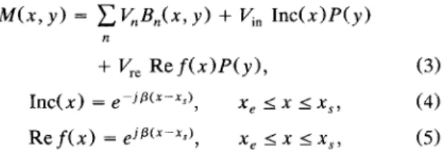
R e f ( x ) P ( y ) , (3)(4) Inc( x ) = e pJPfx-xr), x , I x I x ,
,
where V,, V,,,, and V,, are the coefficients of the bases used to model the higher-order modes, the incident current mode, and the reflected current mode, respectively; x, is the posi- tion of the excitation source; x, is the position of the refer- ence plane (chosen to be the same as that of the short-end discontinuity in this article);
p
is the propagation constant of the coplanar waveguide calculated previously. Employing the fundamental-mode sampling technique [6], we further expand the traveling current modes by the local basis functions as those used to model the higher-order modes. These traveling current modes can be represented aswith x, and xk the positions of the first and last bases used to model the traveling current modes, and
ing the traveling current modes. The length used to charac- terize the coplanar waveguide short-end discontinuity can be reduced, because no extra length is needed to observe the SWR.
C, Matrix Formulation. After the current modeling, we use
the moment method and a nearly Galerkin testing procedure to formulate the characteristic equations. The testing func- tions of the bases used to model the higher-order modes are chosen to be the same as they were originally. The testing functions of traveling current modes are chosen to be the local basis functions adjacent to those modeling the higher- order modes. For the incident traveling current mode, the corresponding testing function is placed at x = xi,,'. For the
reflected traveling current mode, the corresponding testing function is placed at x = x,,.. It is shown in Figure 2(e).
Because the currents on the slots are expanded by only one type of basis function, we can use a tabulation technique to create a table of the reactance integral y l j associated with
the current basis function at x = x, and the testing function at x = xi. If the testing procedure is performed, the charac-
. . . . j : i j i i I .
In principle, the range where the traveling current modes lie can be arbitrary. But to extract the unknown coefficients in the moment method, the range must include at least two
extra local bases at the different positions from those of the bases used to model the higher-order modes. The two extra local bases are used as testing functions of the incident current mode and the reflected current mode. Usually, nu- merical convergence can be improved with a little calculation effort to choose a wider range to represent these traveling current modes. For clearer understanding, the layout of the bases is shown in Figure 2. The delta gap current generator is placed at the position in Figure 2(a). The bases used to model the higher-order modes are shown in Figure 2(b). The inci- dent traveling current mode and the reflected traveling cur- rent mode expanded by local bases are shown in Figures 2(c) and 2(d), respectively. Under such modeling, all currents on slots are expanded by only one type of basis function, includ-
Figure 2 Qualitative representation of the layout of basis functions and the excitation source. (a) The location of the excitation source. (b) The locations of the basis functions used to model the higher-order modes. (c) The location of the incident current mode expanded by local basis functions. (d) The location of the reflected current mode expanded by local basis functions. (e) The locations of the local basis functions used as the testing functions of the traveling current modes in (c) and (d)
teristic equations are in the form of
with
1, if xn, = x , ,
0, else,
In, = (9)
After establishing the matrix elements from the table of
Y j ,
the unknowns can be solved and the reflection coefficient can be obtained from Vre/&.111. NUMERICAL RESULTS AND MEASUREMENT
The coplanar waveguide short-end discontinuity with physical parameters given is characterized by this modified method. The numerical results are shown in Figure 3. In the analysis,
the numerical parameters are set as follows: the size of local basis function is chosen to be A/32 ( A is the guided wave- length of the coplanar waveguide); the number (Nh in Figure
2 ) of the bases used to model the higher-order modes equals
8; the number
(N,
in Figure 2 ) of the bases used to model the traveling current modes equals 17; the number(N,
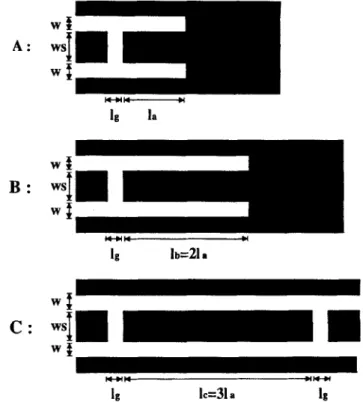
in Figure2) of the extra bases different from the bases used to model the higher-order modes equals 2. So the full length used to characterize the coplanar waveguide short-end discontinuity is only about A/2, and is much smaller than that in the conventional method. Also, a measurement based o n the resonance method [3] is performed to check the validity of our numerical results. Three resonators used to extract the end effect of the coplanar waveguide short-end discontinuity are shown in Figure 4. They are excited through coupling gaps. The lengths of these resonators are chosen as shown in Figure 4, so they have almost the same resonance frequencies
nu-
Ig la
W I
n-nn nn+r
Ig
lc=31
a1s
Figure 4 Three resonators used to extract the end effect of the coplanar waveguide short-end discontinuity
resonance frequencies near the frequency points mentioned above are very close to each other, the propagation constant can be extracted from resonator A and resonator B. Then the coupling gap effect can be obtained from resonator C by the
extracted propagation constant. The short-end effect can be further extracted from either resonator A or resonator B by
the coupling gap effect and by the propagation constant obtained previously. The experimental data are also shown in Figure 3, and show good agreement with the numerical results obtained by the modified method described above. some frequency points. Under the assumption that the
IV. CONCLUSIONS 0.25
-
theory A A measurement 0.2-
0.15-
ws-1).64mm h=0.635mm Er-10.2 25 3( 0 . 0 r . * * *-
I * * ’-
-
-
I * 5 10 15 20 Frequency (GHz)A modification to improve the efficiency of the integral
equation method is proposed in this article. If this method is used, no extra length to observe the SWR in conventional method is needed, and the matrix used to solve the unknown current distribution is reduced. A coplanar waveguide short- end discontinuity is used as an example to describe this modified method. The numerical results are shown to be in good agreement with experimental data.
ACKNOWLEDGMENT
This work was supported in part by the National Science Council under Grants No. NSC 85-2221-E-009-030 and No. CS 85-0210-D-009-008.
REFERENCES
1. W. P. Harokopus and P. B. Katehi, “Characterization of Mi- crostrip Discontinuities on Multilayer Dielectric Substrates In- cluding Radiation Losses,” IEEE Trans. Microwave Theory Tech., Vol. MTT-37, Dec. 1989, pp. 2058-2066.
2. T. S. Horng, W. E. McKinzie, and N. G. Alexopoulos, “Full-Wave 3
Figure 3 Normalized reactance of the coplanar waveguide short-end discontinuity obtained from theoretical results and measurement data
Spectral-Domain Analysis of Compensation of Microstrip Discon- tinuities Using Triangular Subdomain Functions,” IEEE Trans. Microwave 7heory Tech., Vol. MTT-40, Dec. 1992, pp. 2137-2147.
3. M. D. Drissi, V. F. Hanna, and J. Citerne, “Analysis of Coplanar Waveguide Radiating End Effects Using the Integral Equation Technique,” IEEE Trans. Microwave Theory Tech., Vol. MlT-39, pp. 112-116, Jan. 1991.
4. R. W. Jackson and D. M. Pozar, “Full-Wave Analysis of Mi- crostrip Open-End and Gap Discontinuities,” ZEEE Trans. Mi- crowaue Theory Tech., Vol. MlT-33, Oct. 1985, pp. 246-252.
5. H. Y. Yang and N. G. Alexopoulos, “A Dynamic Model for
Microstrip-Slotline Transition and Related Structures,” ZEEE Trans. Microwave Theoy Tech., Vol. MTT-36, Feb. 1988, pp.
6 . T. Rozzi, A. Morini, A. Pallota, and F. Moglie, “A Modified Dynamic Model for Planar Microwave Circuits,” IEEE Trans. Microwave Theoly Tech., Vol. M’IT-39, Dec. 1991, pp. 2148-2153.
7 . T. Itoh, Numerical Techniques for Microwave and Millimeter- Wave Passive Sfructures, Wiley, New York, 1989, Chap. 111.
286-293.
Receiued 2-1 6-96
Microwave and Optical Technology Letters, 12/4, 231-234 0 1996 John Wiley & Sons, Inc.
CCC 0895-2477/96
FORMULAS FOR THE COMPUTATION
OF
THE PHYSICAL PROPERTIES OF
RECTANGULAR MICROSTRIP ANTENNA
ELEMENTS WITH VARIOUS SUBSTRATE
THICKNESSES
Mehmet Kara
Weapons Systems Division
Defence Science & Technology Organisation
PO Box 1500
Salisbury, SA 5108, Australia
KEY TERMS
Antenna physical properties, microstrip, patch antennas, dimensions ABSTRACT
Formulas available in the literature for the design of the physical properties of rectangular microstrip antenna elements are discussed, and their validity is assessed. Their variations have been experimentally examined by analyzing a set of newly designed antenna elements with substrates satisfying the criterion h I 0.0815A0 for 2.22 5 E~ I 10.2, where A, is the free-space wauelength, h isthe thickness, and sr is the relative permittivity of the dielectric substrate. New formulas that can determine the antenna physical properties and the effective dielectric constant are empirically determined. 0 1996 John Wiley & Sons, Inc.
1. INTRODUCTION
The basic microstrip antenna element is a resonant patch of metal on the surface of a grounded dielectric slab. The patch is usually printed on a microwave substrate material with thickness h and relative permittivity E ~ . Its physical proper- ties are the resonant length L , the width W , and the feed point location a, as shown in Figure 1.
Because a microstrip antenna is inhomogeneous and be- cause the radiation appears at the edges of the patch, the physical properties are difficult to determine when designing an antenna for a specified frequency and substrate material. It is well known that the antenna performance characteristics depend largely on the physical dimensions of the patch, the diameter and position of the feed probe, the relative per- mittivity, and the thickness of the substrate on which the antenna element is placed. For example, L affects the reso-
Figure 1
ment with dimensional parameters
Configuration of a rectangular microstrip antenna ele-
nant frequency, the resonant resistance, and the E-plane radiation pattern; W affects the resonant frequency and the H-plane radiation pattern; and the feed-point location con- trols the resonant resistance. It is also known that a rectangu- lar microstrip antenna element radiates efficiently when it resonates, which means that the patch length is approxi- mately one-half of the wavelength in the substrate medium. In practice, the fringing capacitance effect associated with the radiating edges causes the effective distance between the radiating edges to be slightly greater than L, so that
the actual resonant length is slightly less than A,/2, where
A, is the wavelength in the dielectric substrate.
Although several formulas using different levels of approx- imation are available in the literature to design the physical properties of rectangular microstrip antenna elements [l-5, 10-12, 14, 151, there appears to be no reliable general method that gives these properties. The formulas are different, they do not yield similar results, and the ranges of their validity are generally not known. The designed antenna elements using these approximations may not resonate at all for the range of the substrate thicknesses considered in this article. But the designer needs a practical and reliable method for calculating the physical properties of interest for rectangular microstrip antenna elements with various substrate thick- nesses. The designer has thus been forced to obtain the required physical properties by trial-and-error.
The aim of this work is to discuss the published formulas on the design of physical properties of the antenna elements with various substrate thicknesses over a wide frequency band, to stress their suitability and the threshold of their applicability, and to derive new empirical formulas that can determine these antenna physical properties and the effective permittivity of their substrate materials.
2. ELEMENT DIMENSIONS
The published formulas for the design of the physical proper- ties of rectangular microstrip antenna elements are discussed, and their applicability is determined in the following sections.
2.1. Element Width. Patch width is an important considera- tion for both thin and thick antenna elements. Therefore, when selecting the patch width it must be considered that, because of the excitation of surface waves, a small width results in a large bandwidth and in low antenna efficiency and