Interferometric optical sensor for measuring
glucose concentration
Kun-Huang Chen, Cheng-Chih Hsu, and Der-Chin Su
With a specially designed probe, the phase difference between s and p polarization of light reflected under surface-plasmon resonance is measured by use of a common-path heterodyne interferometer. For specific ratios of phase difference to glucose concentration, the glucose concentration can be estimated as a function of the measured phase data. A prototype was set up to demonstrate the feasibility of this sensor, which was experimentally tested in the range 40 –500 mg兾dl with a small quantity of solution and had a measurement resolution of 1.41 mg兾dl at 25 °C. © 2003 Optical Society of America
OCIS codes: 040.2840, 120.3180, 120.5050, 240.6680.
1. Introduction
Measurements of glucose concentration are often parts of biochemical analyses. Several methods for measuring the concentration of a glucose solu-tion have been proposed1– 4; the measurement res-olution was⬃10 mg兾dl. In this paper we propose an interferometric optical sensor for measuring glu-cose concentration that is based on the effect of surface-plasmon resonance5–9共SPR兲 and on hetero-dyne interferometry.3,10 In a specially designed probe, the phase difference between s and p polar-ization of light reflected under SPR is measured with a common-path heterodyne interferometer. For a specific ratio of phase difference to glucose concentration, the glucose concentration can be es-timated from knowledge of the measured phase data. Because the reflected light is measured, only a small quantity of test solution is required. In addition, the probe can easily be operated with high resolution in real time. A prototype has been built to demonstrate its feasibility.
2. Materials and Method
This interferometric optical sensor is shown schemat-ically in Fig. 1. The sensor consists of a heterodyne
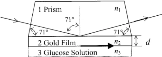
light source, a light-guiding module, a specially de-signed probe, an analyzer共AN兲, a photodetector 共D兲, an electronic signal-processing unit 共ESPU兲, and a seven-segment display. The light-guiding module has two graded-index lenses, L1 and L2, and a polarization-maintaining fiber共PMF兲. The specially designed probe is an isosceles trapezoid prism with base angle 71°; a thin gold film is deposited upon its base surface, which is in contact with the test glucose solution, as shown in Fig. 2. So this probe is a SPR apparatus in a Kretschmann–Raether configura-tion.8
For convenience, the⫹z axis is chosen to be along the direction of light propagation and the⫹x axis is along the horizontal plane. The light beam coming from the heterodyne light source has a frequency difference f between s and p polarization, and its polarization plane lies at angle␣ to the x axis. This light beam is guided into the polarization-maintaining fiber by lens L1and is collimated by lens L2 attached to one side surface of the probe. Then the light beam penetrates the surface normally and is incident at 71° onto the boundary surface between the prism and the thin gold film. Because the base angle is designed to be 71°, the incident angle is near the resonant angle. Consequently the surface plas-mons are excited. The reflected light beam passes through the analyzer with the transmission axis at 45° to the x axis and is detected by the photodetector. The detected intensity is
It⫽ 兩Et兩2
⫽1⁄4关cos2␣r
p2⫹ sin2␣rs2
⫹ 2 cos ␣ sin ␣rprscos共2ft ⫹ 兲兴, (1) The authors are with the Institute of Electro-Optical
Engineer-ing, National Chiao Tung University, 1001 Ta-Hsueh Road, Hsin-Chu 300, Taiwan, China. D.-C. Su’s e-mail address is [email protected].
Received 26 February 2003; revised manuscript received 1 July 2003.
0003-6935兾03兾285774-03$15.00兾0 © 2003 Optical Society of America
where rpand rsare the reflection coefficients of p and
s polarization, respectively, and is the phase
differ-ence between the p and s polarization coming from the reflection at the boundary surface under the con-ditions of SPR5,8: rq⫽ r12q⫹ r23qexp共i2kz2d兲 1⫹ r12qr23qexp共i2kz2d兲 , q⫽ p, s, (2) ⫽ arg共rp兲 ⫺ arg共rs兲, (3)
where kz2is the wave vector in the thin gold film, d is the thickness of the thin gold film, rij
q
is the Fresnel reflection coefficient between the ith and the jth me-dia, and subscripts i and j are any of 1共glass prism兲, 2 共thin gold film兲, or 3 共glucose solution兲, whose re-fractive indices are n1, n2⫽ n ⫹ ik, and n3, respec-tively.
The electrical modulation signal of the heterodyne light source is filtered and becomes the reference sig-nal. It has the same form and can be expressed as10
Ir⫽1⁄2关1 ⫹ cos共2ft兲兴. (4)
Both of these two sinusoidal signals are sent to the electronic signal-processing unit, and can be ob-tained. From Eqs.共2兲 and 共3兲 it is obvious that is strongly dependent on n3. In general, n3 is nearly proportional to its associated concentration c. By substituting the data of into a specific ratio of versus c, we can estimate the associated concentra-tion c.
3. Experiments and Results
To demonstrate the feasibility of the proposed instru-ment we set up a prototype of this interferometric optical sensor to test glucose solutions of different concentrations at three temperatures. The hetero-dyne light source11consisted of a He–Ne laser with wavelength 632.8 nm, a half-wave plate, and an electro-optic modulator driven by a function genera-tor. The conditions f⫽ 1 kHz and ␣ ⫽ 5° were used. The specially designed probe was a BK7 isosceles trapezoid prism with base angle 71° and a thin gold film of 40-nm thickness deposited onto its back sur-face. The refractive indices of the prism and the thin gold film were measured in advance with an ellipsometer共Model Eta; Stag, Inc.兲 and were 1.5151 and 0.2108⫹ 3.5963i, respectively, at a wavelength of 632.8 nm. Test solutions were prepared according to the definition of concentration in weight percent. Chiral parameter g of each solution was measured with the optical heterodyne polarimeter proposed by Lin and Su.12 Then the concentration of each solu-tion could be calibrated by comparison of the mea-sured g and the data from Ref. 13. For convenience, the light-guiding module was omitted from our ex-periments, and we let the light beam be incident normally onto the side surface of the probe.
The experimental results and their associated fit-ting curves appear in Fig. 3, where the measurement results at 15, 25, and 35 °C are shown. It is clear that with this optical sensor and the associated ratio of to c at a nominal temperature, the concentration of glucose solution can be obtained from the mea-sured data of.
4. Discussion
In our experiment there were two extreme conditions, 40 mg兾dl at 35 °C and 500 mg兾dl at 15 °C. The associated plasmon resonant angles were 71.06° and 70.95°, respectively. Although the plasmon reso-nant angle varied with the concentration, the shift in resonant angle in our experiments was small. For convenience, the incident angle in the probe was fixed to 71°, which is the resonant angle associated with a concentration of 40 mg兾dl at 25 °C. Consequently,
Fig. 1. Schematic diagram of the optical sensor.
Fig. 2. Reflection at the boundary surface between a prism and a thin gold film under SPR.
Fig. 3. Measurement results and associated fitting curves of phase difference versus glucose concentration at 15, 25, and 35 °C.
reflection coefficient rpwas small. So the condition ␣ ⫽ 5° was used in our experiments to enhance the contrast of the test signal.
Considering the angular resolution of the elec-tronic signal-processing unit, the polarization-mixing errors, and the second-harmonic error, the total phase difference errors 兩⌬兩 could be decreased to 0.03° in our experiments.14 Slopes s of the three fitting curves for 15, 25, and 35 °C in Fig. 3 were 0.0134, 0.0213, and 0.0167 deg共dl兾mg兲, respectively. Then, substituting these data into the following equa-tion:
⌬c ⫽ 兩⌬兩兾s, (5)
we obtained the associated resolutions⌬c of the mea-surement. They were 2.24, 1.41, and 1.8 mg兾dl, re-spectively, and were better than those obtained with the previous methods.2,3 The main reason for the better resolution is that this sensor operates under conditions of SPR; hence a small variation in the concentration can introduce an abrupt variation in optical phase. This phase variation can be mea-sured accurately by the optical heterodyne interfero-metric technique. As a result, this method provides better resolution. In addition, the incident angle is equivalent to the resonant angle at 25 °C, so the mea-surement resolution at 25 °C is the best in our exper-iments.
Although the measurement resolution is enhanced as the thin gold film becomes thicker, both the inten-sity and the contrast of the test signal decrease rap-idly. To compensate for these conditions, we chose
d ⫽ 40 nm for our experiments. In addition, if a
light-guiding module is added, the probe can be moved conveniently to the test solution, and this sen-sor can be operated easily.
5. Conclusions
In this paper we have proposed an interferometric optical sensor for measuring glucose concentration that is based on the effect of surface plasmon reso-nance and on heterodyne interferometry. Because of the introduction of a light-guiding module, its own common-path interferometric configuration, and the presence of an electronic signal-processing unit, this sensor has such merits such as a simple structure, easier operation in real time, rapid measurement, and high stability. A prototype was set up to dem-onstrate its feasibility, which was experimentally
tested in the range 40 –500 mg兾dl and had a mea-surement resolution of 1.41 mg兾dl at 25 °C.
This study was supported in part by the National Science Council, Taiwan, under contract NSC 91-2215-E-009-020.
References
1. Y. Liu, P. Hering, and M. O. Scully, “An integrated optical sensor for measuring glucose concentration,” Appl. Phys. B 54, 18 –23共1992兲.
2. C. Chou, Y. C. Huang, C. M. Feng, and M. Chang, “Amplitude sensitive optical heterodyne and phase lock-in technique for small optical rotation angle detection of chiral liquid,” Jpn. J. Appl. Phys. 36, 356 –359共1997兲.
3. C. M. Feng, Y. C. Huang, J. G. Chang, M. Chang, and C. Chou, “A true sensitive optical heterodyne polarimeter for glucose concentration measurement,” Opt. Commun. 141, 314 –321 共1997兲.
4. R. J. Mcnichols and G. L. Cote, “Optical glucose sensing in biological fluids: an overview,” J. Biomed. Opt. 5, 5–16 共2000兲.
5. Y. C. Cheng, W. K. Su, and J. H. Liou, “Application of a liquid sensor based on surface plasma wave excitation to distinguish methyl alcohol from ethyl alcohol,” Opt. Eng. 39, 311–314 共2000兲.
6. C. H. Liao, C. M. Lee, L. B. Chang, and J. H. Tsai, “Effects of a metal film and prism dielectric properties of surface plasmon resonance in a multilayer,” Jpn. J. Appl. Phy. 36, 1105–1111 共1997兲.
7. Y. C. Cheng, W. K. Su, C. M. Lee, L. B. Chang, J. H. Liou, J. M. Shen, and T. H. Scoong, “Design and measurement of a dielec-tric sensor based on surface plasma excitation,” Appl. Surf. Sci. 136, 260 –267共1998兲.
8. A. A. Kolomenskii, P. D. Gershon, and H. A. Schuessler, “Sen-sitivity and detection limit of concentration and absorption measurements by laser-induced surface-plasmon resonance,” Appl. Opt. 36, 6539 – 6547共1997兲.
9. K. J. Kasunic, “Comparison of Kretschmann–Raether angular regimes for measuring changes in bulk refractive index,” Appl. Opt. 39, 61– 64共2000兲.
10. M. H. Chiu, J. Y. Lee, and D. C. Su, “Refractive index mea-surement based on the effects of total internal reflection and the use of heterodyne interferometry,” Appl. Opt. 36, 2936 – 2939共1997兲.
11. D. C. Su, M. H. Chiu, and C. D. Chen, “Simple two-frequency laser,” Precis. Eng. 18, 161–163共1996兲.
12. J. Y. Lin and D. C. Su, “A new type of optical heterodyne polarimeter,” Meas. Sci. Technol. 14, 55–58共2003兲.
13. T. W. King, G. L. Cote, R. McNichols, and M. J. Goetz, Jr., “Multispectral polarimetric glucose detection using a single Pockels cell,” Opt. Eng. 33, 2746 –2753共1994兲.
14. M. H. Chiu, J. Y. Lee, and D. C. Su, “Complex refractive-index measurement based on Fresnel’s equation and the uses of heterodyne interferometry,” Appl. Opt. 38, 4047– 4052共1999兲.