Construction and Soccer Dynamics Analysis for an Integrated
Multi-agent Soccer Robot System
HAN-PANG HUANG, CHAO-CHIUN LIANG, AND CHUN-WEI LIN
Robotics Laboratory Department of Mechanical Engineering
National Taiwan University Taipei, Taiwan, R.O.C.
(Received February 22, 2000; Accepted April 26, 2000)
ABSTRACT
An integrated multi-agent robot system (NTU-Formosa) for robot soccer games was built in this study. The system consists of multiple mobile robots, a vision system, a wireless communication system, and a host computer. The multiple robots can be cooperatively controlled as they play a robot soccer game in an unknown and dynamic environment. The development of the system involved mechanism design and manufacture, integration of the electromechanical system, vision servoing, pattern recognition, decision-making, wireless communication, motion control, and centralized coordination control. The developed system has satisfactory performance in terms of compactness, stability, robustness, and mobility. To better understand the behaviors of the ball and robots in a robot soccer game, the free motion dynamics of the robots and ball and the collision dynamics among them were derived and analyzed in this study. To coordinate the multiple robots well, a flexible strategy-based decision-making system is proposed to perform centralized control. An experiment was conducted to examine the performance of NTU-Formosa, and the results obtained are satisfactory.
Key Words: multi-agent robot, vision servoing, pattern recognition, centralized coordination control
I. Introduction
Multiple robots can cooperatively perform tasks that are difficult for a single robot. Coordination of multiple robots increases the flexibility and robustness of the system at the expense of increasing the complexity involved in performing tasks. It is less serious when one robot malfunctions in a multi-ple-robot system. The advantages of multi-agent robot systems have led to their extensive use in the area of manufacture automation. Although multi-agent robot systems can perform very complicated cooperative tasks in determinate and static environments, they cannot work effectively in unknown and dynamic circumstances. There are many applications, however, in which the environments are unknown and dynamic, such as factory and building security, shore patrol, and robot police, etc. Therefore, an intelligent and adaptive multi-agent robot system applicable to unknown and dynamic environments is desired.
In this study, we built an integrated multi-agent robot system, called NTU-Formosa, designed to play robot soccer games in order to study its performance in unknown and dynamic environments. Furthermore, this system can be a test-bed for real time decision making, pattern recognition, wireless communication, vision servoing, electromechanical systems, motion control, sensor fusion, multiple mobile robots coordination and competition, behavior learning, etc. (Kitano
et al., 1997). Many multi-agent robot systems capable of
playing robot soccer games have been built (Barman et al., 1993; Kim et al., 1997a, 1997b; Park et al., 1997; Shen et
al., 1998a). The system developed in this study has
perfor-mance competitive with theirs. It has the characteristics of vision servoing, centralized coordination control, a compact body, impact resistance, and modular design. The system consists of four major sub-systems: multiple mobile robots, a vision system, a wireless communication system, and a host computer.
In a robot soccer game, two teams whose behavior may be difficult to anticipate dynamically compete with each other. Therefore, both teams in a soccer game face a highly com-plicated dynamic environment including the ball and robots. To better understand the behaviors of the ball and robots in a robot soccer game, the free motion dynamics of the ball and robots and the collision dynamics among them were derived and analyzed in this study. The derived dynamics were also useful in designing NTU-Formosa. To coordinate the multiple robots well, a flexible strategy-based decision-making system was employed to perform centralized control. Because the proposed decision-making system is strategy-based, it is more flexible than other types of systems. To examine the perfor-mance of NTU-Formosa, experiments involving ball shooting, goal keeping, and a one-to-one soccer game were conducted in this study.
The organization of this paper is as follows. Our in-tegrated multi-agent robot system is presented in Section II. In Section III, this paper derives and analyzes the free motion and collision dynamics. In Section IV, the intelligent strategy-based decision-making system is presented. Experiments conducted to study the performance are described in Section V. Finally, several concluding remarks are made.
II. An Integrated Multi-Agent Soccer
Ro-bot System
The integrated multi-agent soccer robot system built in this study is called NTU-Formosa. The architecture and components of NTU-Formosa are described in the following sub-sections.
1. System Architecture
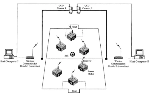
NTU-Formosa consists of multiple mobile robots, a vision system, a wireless communication system and a host computer (Huang et al., 1998; Shen et al., 1998b). To provide physical insight into the system, a graphical diagram of two competing teams in NTU-Formosa and their components are shown in Fig. 1. The image information of the whole soccer field is captured by a CCD camera (CCD-300U, a Charge-Coupled Device (CCD) camera manufactured by Mitsubishi Electric, Japan) and sent to the corresponding host computer. The host computer then analyzes the image information to determine the situation on the soccer field, including the positions, orientations, and velocities of the ball and soccer robots. According to the determined situation, the host com-puter decides on a strategy and plans the motion modes and the corresponding velocity commands for every soccer robot
on the same team. Each soccer robot in NTU-Formosa then receives velocity commands from the host computer and regulates the rotational velocities of its right and left wheels. The above-mentioned operations constitute a complete com-mand cycle. The time needed for a comcom-mand cycle should be as short as possible and should be considered in the situation recognition.
The operation of a command cycle can be easily un-derstood from the system block diagram shown in Fig. 2. As shown in Fig. 2, global monitoring, including high-level motion planning, is performed by the vision system and host computers. Local control, including low-level motion control, is executed by the 8051s (single-chip micro-controllers originally devel-oped by Intel) on the robots. From Figs. 1 and 2, it is apparent that the soccer robots in NTU-Formosa are remote-brain robots; i.e., environmental perception, decision-making, and motion planning are performed by a remote host computer (Hong et al., 1997; Kim et al., 1998; Mediavilla et al., 1998).
2. Mechanical Design
In the mechanical design of the mobile robots, this study considered three important factors: size, robustness, and efficiency. In official robot soccer games, such as RoboCup (Kitano el al., 1997) and MIROSOT (Park et al., 1997), there are restrictions on the size of the soccer robots. In MIROSOT, for example, the size of each soccer robot must be 7.5 cm × 7.5 cm × 7.5 cm or less. The size of each soccer robot in NTU-Formosa follows this rule. Therefore, when selecting parts for the soccer robots, size had to be considered. To reduce the size of the circuit board, most of the electronic parts in the robots are of the surface mount type. In order to reduce the size of the gear set, we adopted simple reduction Fig. 1. Graphical diagram of two competing teams in NTU-Formosa.
gears to transmit torque from the motor to the wheels. On the other hand, we also tried our best to reduce the complexity of the circuits and mechanisms in the robots in order to both reduce the size of each soccer robot and increase the efficiency and reliability of the system. Collisions between soccer robots are a part of robot soccer games. Hence, the mechanisms used in NTU-Formosa were designed to be impact resistant.
The framework of each soccer robot is made of acrylic material. The weight of a soccer robot is about 290 grams. The framework includes three layers: the bottom layer contains motors, encoders and gear sets; the middle layer holds batteries; and the top layer consists of a circuit board and a wireless receiver. Because most of the weight of a soccer robot is in the lower layer, this arrangement has the advantage of a lower center of gravity so it is unlikely to turn over while turning or colliding. Since the robots incorporate a modular design, the reduction gears and other parts can be quickly replaced. With this advantage, NTU-Formosa can easily maintain fight-ing power durfight-ing a violent soccer game.
As the mobility of soccer robots increases, their offensive and defensive capabilities increase accordingly. Considering both mobility and cost, the maximum linear speed of our soccer robots is designed to be 1 m/s. The diameter of the wheels and the reduction ratio were selected to be 30 mm and 1/15, respectively. The required rotational speed of the motors can then be obtained as
ω = 15 × (1/0.03π × 60) = 9549 RPM. (1) Selection of gears involved consideration of size and cost. After we surveyed many types of gears, we adopted plastic for the reduction gears. The selected plastic gears can with stand torques up to 2000 g-cm and meet the physical requirements. However, they still suffer from wear. This problem was compensated for by making gear replacement very easy.
3. Motion Control Hardware and Wireless Commu-nication System
Motion control of each soccer robot is achieved using an 8051 and two sets of mini DC motors, PWM drivers and encoders. They form two closed-loop feedback control sys-tems which accurately control the velocity of the two wheels. A block diagram of the motion control is shown in Fig. 3. By means of an RS-232 (serial port interface), the wireless communication module sends a command to the 8051 as shown in Fig. 3. The 8051 processes the command and the encoder signals, and then sends pulse signals to PWM drivers. All the control circuits are laid out on the PCB boards placed in the top layer of the soccer robot framework. The adopted motor is MABUCHI RF202TH, manufactured by Mabuchi, Japan, and the selected PWM (Pulse Width Modulation) driver is LM629, manufactured by National Semiconductor, U.S.A. For soccer robots to be able to move freely, the motion command should not be sent through wires. Our wireless communication module changes digital command signals into radio signals and sends them to the receivers on the soccer robots. The receivers then demodulate the radio signals, changing them into digital signals. This is how the host computer communicates with the soccer robots. Communi-cation is unidirectional to reduce the size and cost.
There are two major problems lie in the design of a wireless communication system: size and signal stability. The size of a receiver on a soccer robots must be minimized to satisfy size restrictions. Since the receiver circuit is more complex than the transmitter circuit, the size of the receiver is much larger than that of the transmitter. This makes the design and manufacture of a wireless communication system much more difficult. Signals can be transmitted in either AM or FM. Because the quality of AM is often influenced by the arrangement of the objects in the environment, we selected FM. There are two commonly used FM bands: UHF and VHF. Since the environment usually interferes with VHF, NTU-Formosa employs UHF. For the above-mentioned reasons, we adopted commercialized modular wireless communication modules: TXM-418-A transmitter and SILRX-418-A receiver modules manufactured by Radiometrix, U.K.1
The advantages of the selected modules are stable signals and compact size.
Fig. 2. System block diagram of NTU-Formosa.
Fig. 3. Motion control of soccer robots. 1
4. Vision System and Host Computer
The vision system of NTU-Formosa consists of a CCD camera, an image capture card, and a library of image pro-cessing functions. In robot soccer games, the CCD camera is hung over the game field to continuously capture and send images of the field to the host computer through the image capture card. Using a library of image processing functions, each live image is analyzed by the host computer to get information about the field. The field information is then sent to the decision and control system for computation of new motion commands. Hence, the vision system is an important feedback sensor in NTU-Formosa, and its speed and resolution are very crucial to overall performance. A diagram of the vision system is shown in Fig. 4. We adopted the Matrox Meteor-II (PCI frame grabber) image-capture card and the MIL (Matrox Imaging Library) 5.1 image processing library, both manufactured by Matrox Electronics System Ltd, Canada. Processing and recognizing the entire soccer field in every command cycle is very time-consuming and decreases the mobility of the soccer robots. Therefore, NTU-Formosa tracks each soccer robot in order to predict its motion. This can reduce the recognition area and the processing time, and increase mobility. NTU-Formosa sends motion commands at 30 Hz, which is the maximum frame-per-second rate of the adopted NTSC CCD camera. If a Progressive Scan CCD camera is used, the maximum frame-per-second rate increases to 60 Hz, and NTU-Formosa can send motion commands at 60 Hz.
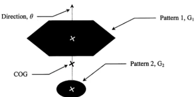
For recognizing the position and direction of each robot, we placed two well-designed patterns on top of the robots, as shown in Fig. 5. In Fig. 5, Gi is the center of gravity of pattern i, i = 1, 2; COG is the center of gravity of the robot; θ is the direction of the robot. G1 and G2 can be easily identified
by the imaging system. COG and θ can be computed from G1 and G2 by means of simple geometry.
The host computer receives field information from the vision system, analyzes it to make decisions about strategies and actions, and finally sends motion commands to the soccer robots. Therefore, the host computer contains the vision
system software, decision and control systems, and wireless communication interface. A block diagram of the host com-puter is shown in Fig. 6.
The decision system is composed of the strategy and action selections shown in Fig. 6. The feedback control system uses field information as feedback data and motion commands as actuator signals, as shown in the block diagram in Fig. 6.
III. Soccer Dynamics
In this section, the free motion of the ball and robots, and the collision dynamics among them are derived and analyzed.
1. Free Motion Dynamics
Free motion in this study is defined as follows: An object is in free motion when it moves without constraint in its motion space. The motion space in a robot soccer game is a two-dimensional plane parallel to the soccer field. There are two free motions: one for the ball and the other for the robots.
A. The Free Motion of the Ball
There are two modes of free motion of the ball. One is pure rolling without sliding, and the other has rolling and sliding. When the motion is pure rolling without sliding, there is no friction force, and the free motion of the ball is shown in Fig. 7. In Fig. 7, ω is the angular velocity, r is the radius,
v = ωr is the linear velocity, mb is the mass, g is the gravity, and N is the normal reaction force with magnitude equal to mg.
Fig. 4. The vision system.
Fig. 5. The patterns on top of the soccer robots and the method used to
calculate the position and direction.
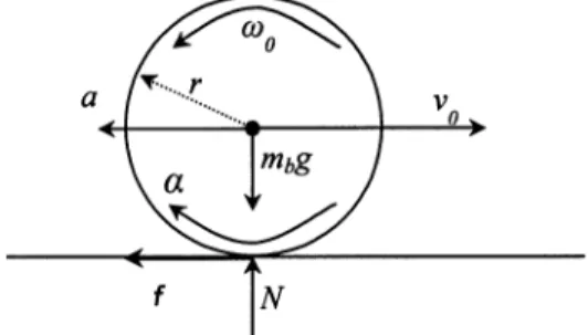
After colliding with a wall or robot, the velocity of the ball may be changed, and sliding may occur. For example, if the ball collides perpendicularly with a wall with velocity
v0, then the motion of the ball just after the collision is rolling
plus sliding, as shown in Fig. 8. Note that ω0 is the angular
velocity just after the collision, α is the angular acceleration,
a is the linear acceleration, f is the friction force, and the other
symbols have the same meaning as in Fig. 7.
Because of the sliding motion, f is a dynamic friction force and can be formulated as
f = µdmbg, (2)
where µd is the dynamic friction coefficient between the ball and the soccer field. The angular motion of the ball is described by α =– fr Ib =– 5µdmbgr 2mbr2 =– 5µdg 2r , (3) ω(t) = ω0+αt = ω0– 5µdg 2r t , (4) where Ib = (2mbr2)/5 is the moment of inertia of the ball with respect to the rotation axis. The linear motion of the ball is described by the following equations:
a =m– f
b = –µdg , (5)
v(t) = v0 + at = v0− µdgt. (6)
Equations (3) − (6) are valid until v(t) = −ω(t)r. At that moment, the sliding motion stops, and the motion of the ball becomes pure rolling. The corresponding time tc, linear velocity vc, and angular velocity ωc are given as
tc= 4v0 7µdg , (7) vc= 37v0, (8) ωc= – 3 7ω0. (9)
B. The Free Motion of the Robots
In this study, every robot has two wheels. For each robot, the motion of its center of gravity can be obtained from its two wheels, as shown in Fig. 9. Note that mR is the mass of the robot, vr and ar are the velocity and acceleration of the right wheel, respectively, vl and al are the velocity and ac-celeration of the left wheel, respectively, v and a are the velocity and acceleration of the center of gravity, respectively, ω and α are the angular velocity and acceleration of the robot, rR is one half of the distance between the centers of the two wheels, and IR = (2mRrR2)/3 is the moment of inertia of the robot with respect to the rotation axis.
From Fig. 9 and the kinematics of wheeled vehicles, the motions of the robot, v, a, ω and α, can be obtained as
v = 1 2(vr+ vl) , (10) a = 1 2(ar+ al) , (11) ω =vr– vl 2rR , (12) α =ar– al 2rR . (13)
Considering the sliding effects, there are also two modes of free motion of the robots: pure rolling and rolling plus sliding. Since the motion of a robot can be determined from its wheels, the following discussion considers only one of the two wheels of the robot. Different from the free motion of the ball, an active torque from the motor is output to the wheel. When there is no sliding, the free motion of a wheel of a robot Fig. 7. The free motion of the ball without sliding.
Fig. 8. The free motion of the ball with rolling and sliding.
is that shown in Fig. 10. Note that Tr is the driving torque of the wheel, and all the other symbols have the same meaning as in Fig. 8.
The angular acceleration of the wheel is given by
α =Tr– fr
Ir
, (14)
where Ir = (mrr2)/2 is the moment of inertia of the wheel with respect to its rotation axis, and mr is the mass of the wheel. Because there is no sliding, “f = mra” and “a = rα” can be applied to Eq. (14), and the linear and angular accelerations of the wheel and the friction force can be obtained as
a = 2Tr 3mrr , (15) α = 2Tr 3mrr2 , (16) f =2Tr 3r . (17)
After colliding with a wall, with other robots, or with the ball, the velocity of the robot may be changed, and sliding may occur. This situation is shown in Fig. 11.
The linear and angular accelerations of the wheel and the friction force can be easily derived as
a = µdg, (18) α = 2Tr mrr2 +2µdg r , (19) f = µdmrg. (20) 2. Collision Dynamics
The collision dynamics of robot-to-ball, robot-to-robot, robot-to-wall, and ball-to-wall are important when designing and using offensive and defensive strategies. Precise identi-fication of the collision dynamics increases the accuracy of shooting, dribbling and passing, and the efficiency of inter-cepting and blocking (Mizuno et al., 1996, 1997). In this study,
modeling of collisions is based on the following assumptions: ASSUMPTION I: The soccer field and the walls are fixed to the ground and are as-sumed to have infinite mass. ASSUMPTION II: During the collision period, the
only energy dissipation is caused by the friction between the two objects colliding with each other. ASSUMPTION III: The robots, ball, walls, and soccer
field are rigid.
When the ball collides with a wall with velocity v, it is rebounded back with a different velocity v′. If the vertical and horizontal components of v are, respectively, vv and vh, and if those of v′ are vv′ and vh′, respectively, then based on the above three assumptions, the following relationships can be obtained: “vh′ = vh” and “vv′ = −vv”. That is, the ball is rebounded back with the same magnitude of the vertical velocity and maintains the same horizontal velocity.
Compared to the ball, a robot has an active driving torque and a different shape. Therefore, when a robot collides with a wall with velocity v, its response is very different from that of the ball. According to the incident angle θ of a robot colliding with a wall, there are three kinds of collisions, as shown in Fig. 12. In Fig. 12, v and v′ are the velocities before and after collision, respectively, ω is the angular velocity after collision,
Fv and Fh are the vertical and horizontal average reaction forces during collision, respectively, θc is the critical angle when no rotation occurs, and d is one half of the length of the diagonal Fig. 10. The free motion of a wheel of a robot without sliding.
Fig. 12. Three kinds of collisions of a robot with a wall. Fig. 11. The free motion of a wheel of a robot with sliding and rolling.
of the robot’s top view. Note that point contact is assumed here. This study also assumes that the duration of collision is ∆t, and that the top view of the robot is square in shape.
The linear velocity v′ can be obtained from v as
vv′= – vv,
vh′ = vh+
Fh
mR∆t . (21)
The angular velocity ω in Fig. 12(a), (b) and (c) are given, respectively, in Eqs. (22a) − (22c) as
(22a) ω = ω0– d[– Fvcos(θ + π4) +Fhsin(θ + π4)]∆t IR , 0 , ω0+ d[Fvcos(θ + π 4) –Fhsin(θ + π4)]∆t IR , (22b) (22c)
where ω0 is the angular velocity just before collision and IR has the same meaning as in Fig, 9. π/4 in Eq. (22) results from the square shape of the robot’s top view. The vertical average reaction force Fv can be approximated by the following equation:
Fv=
2mRvsinθ
∆t , (23)
where mR is the mass of the robot. Considering both static and dynamic friction, the horizontal average reaction force Fh can be approximated by the following equation:
Fh= 2mRvcosθ ∆t , if 2mRvcosθ ∆t ≤µrwsFv µrwdFv, if 2mRvcosθ ∆t ≤µrwsFv (24)
where µrws and µrwd are the static and dynamic friction co-efficients between the robot and the wall respectively. The angle θsd at which the static friction is about to change to dynamic friction can be obtained from Eqs. (23) and (24) as
θsd= tan
– 1
( 1µ
rws) . (25)
By equating the torques caused by Fv and Fh, the critical angle can be obtained as θc= tan – 1 (Fv Fh ) – π 4. (26)
When the ball with velocity vb collides with a robot with
velocity vr, based on assumptions I, II, and III, the responses of the ball and the robot can be given as
vbv′ = mb– mR mb+ mR vbv+ 2mR mb+ mR vrv, (27a) vbh′ = vbh, (27b) vrv′ = 2mb mb+ mR vbv+ mR– mb mb+ mR vrv, (27c) vrh′ = vrh, (27d)
where the superscript ′ means the velocity after collision and the subscripts v and h represent, respectively, the vertical and horizontal components of the corresponding velocity. The vertical and horizontal components are measured with respect to the plane tangent to the ball and the robot at the point of collision. The angular velocity of the robot after collision can be obtained similarly from Eqs. (22) − (24). When one robot collides with another robot, both their motions after collision can be similarly obtained from Eqs. (22) − (27).
IV. Decision System
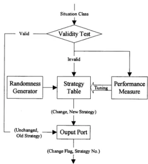
As stated in Section II.4, the decision system is composed of the strategy and action selections. The block diagrams of the strategy and action selections are shown in Figs. 13 and 14, respectively.
The strategy selection shown in Fig. 13 is explained in the following. The strategy table contains all the user-devel-oped strategies. The validity test receives information about the field situation from the vision system and then tests the validity of the current strategy. If the result is valid, the current
strategy will not be changed. If the result is invalid, the strategy will be changed to a new one, and the test result will be sent to the performance measure for tuning of the strategy table. The randomness generator here disguises the opponents. In a given situation, the strategy table randomly outputs a strategy from a set of equivalent strategies.
The process of action selection shown in Fig. 14 is explained in the following. The performance measure and randomness generator have the same functions as in Fig. 13. For a given strategy and status, the success probabilities of the candidate actions are analyzed. According to the analysis results, the action decision rules are used to select a set of suitable actions, and the motion commands are output to the soccer robots. A detailed discussion of the strategy and deci-sion system has been given in another paper (Huang et al., 1998).
V. Experiments
In this study, the developed strategies and decision and control system were employed in experiments on NTU-Formosa to examine the system performance.
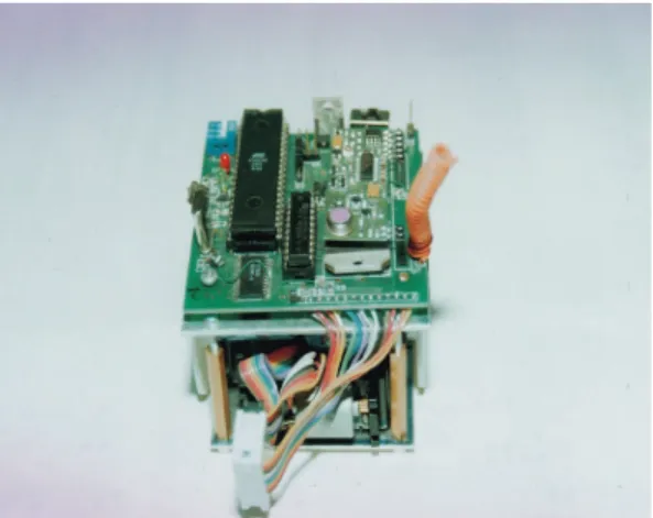
A soccer robot for NTU-Formosa designed and manu-factured in this study is shown in Fig. 15. In Fig. 15(a), the coil in the upper-right corner is the antenna for receiving radio signals; the small PCB beside the antenna is the receiver of the wireless communication module; the black rectangle chip in the upper-left corner is the micro-controller 8051. In Fig. 15(b), the small black plastic box behind the wheel contains a gear set and an encoder. The motor driving the wheel is also behind the wheel.
In this study, we conducted a series of experiments to examine the performance of the designed and manufactured soccer robots. As for motion capacity, the experimental results show that the maximum speed of the robot is 1.2 m/s. The soccer robot can rotate any angle about an axis perpendicular to the soccer field and can track most smooth paths.
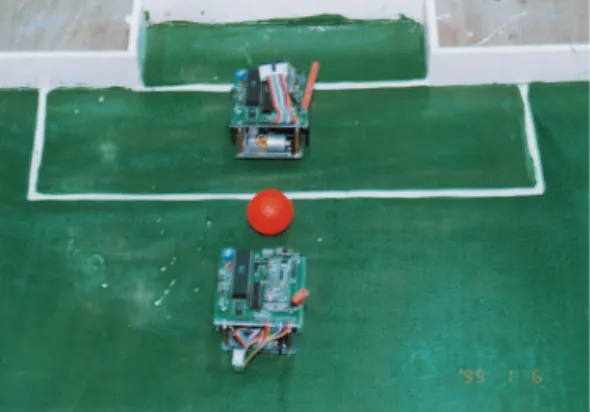
The robots control the ball through a series of kicks, as shown in Fig. 16. Therefore, the robots can control the ball and track smooth paths in a piecewise manner. If the tracking speed is set to be 0.7 m/s, the maximum tracking error is smaller than the radius of the ball. The experimental results also show that the tracking error is approximately proportional to the tracking speed.
The experiment examined the shooting performance in two ways, static shooting and dynamic shooting, and in two areas, the goal area and offensive zone outside the goal area. In static shooting, the probability of successful shooing is 90% in the goal area and is 70% in the offensive zone outside the goal area. The speed of the ball was also set to 0.5 m/s to examine the dynamic shooting performance. In dynamic shooting, the probability of successful shooing is 52% in the goal area and 33% in the offensive zone outside the goal area. The lower probability of dynamical shooting resulted from the slow vision servoing rate and incomplete identification of soccer dynamics.
Fig. 14. Block diagram of the action selection process.
(a) Upper-rear view of a soccer robot.
(b) Upper-left view of a soccer robot. .
Fig. 15. A soccer robot for NTU-Formosa designed and manufactured in
To examine the goal keeping capacity, in this experiment we set one robot on the center of the goal line to defend the goal and another robot in the offensive zone, which shot a static ball toward the goal. The maximum shooting speed was 1 m/s. The probability of successful goal keeping was 81%. The slow vision servoing rate was the main reason for the lower probability.
The average time to goal in a one-to-one soccer game, as shown in Fig. 16, was about 10 minutes. This result is acceptable but not satisfactory. To improve performance, the vision servoing rate must be increased, and the soccer dynam-ics should be identified more completely.
VI. Conclusions
In this study, we built a vision servoing based integrated multi-agent robot system. Multiple robots can efficiently execute cooperative tasks in unknown and dynamic environ-ments, such as in a robot soccer game. The designed and manu-factured robots are compact, stable, and modular. Their com-pact design increases their efficiency, reliability, and mobility. Their stable design lowers their center of gravity so that they can remain stable during fast motion and collision. Their modular design speeds up the processes of manufacture,
assembly and repair. The experimental results show that the performance of the robots is satisfactory.
This study derived the free motion dynamics of the ball and the robots, and the collision dynamics among them. The derived dynamics were useful in designing NTU-Formosa and understanding the behaviors of the ball and robots. The experi-mental results show that the derived dynamics are satisfactory, and that precise identification of the collision dynamics is crucial for good performance in shooting, dribbling, goal-keeping, passing, and intercepting. The proposed strategy-based decision-making system was also studied in the experiment, and the results were satisfactory. Pattern recog-nition and the decision system will be discussed in future papers.
References
Barman, R. A., S. J. Kingdon, J. J. Little, A. K. Mackworth, D. K. Pai, M. Sahota, H. Wilkinson, and Y. Zhang (1993) DYNAMO: real-time experiments with multiple mobile robots. Proceedings of Intelligent
Vehicles Symposium, pp. 261-266, Tokyo, Japan.
Hong, C. S., S. M. Chun, J. S. Lee, and K. S. Hong (1997) A vision-guided object tracking and prediction algorithm for soccer robots. IEEE Int'l.
Conf. on Robotics and Automation, pp. 346-351, Albuquerque, NM,
U.S.A.
Huang, H. P., C. C. Liang, and C. W. Lin (1998) Building a multi-agent robot system for robot soccer game and developing game strategies based on soccer dynamics. Int'l. Conf. on Mechatronic Technology, pp. 303-308, Hsinchu, Taiwan, R.O.C.
Kim, J. H., H. S. Shim, H. S. Kim, M. J. Jung, I. H. Choi, and J. O. Kim (1997a) A cooperative multi-agent system and its real time application to robot soccer. IEEE Int'l. Conf. on Robotics and Automation, pp. 638-643, Albuquerque, NM, U.S.A.
Kim, K. H., K. W. Ko, J. G. Kim, S. H. Lee, and H. S. Cho (1997b) The development of a micro robot system for robot soccer game. IEEE Int'l.
Conf. on Robotics and Automation, pp. 644-649, Albuquerque, NM,
U.S.A.
Kim, J. H., K. C. Kim, D. H. Kim, Y. J. Kim, and P. Vadakkepat (1998) Path planning and role selection mechanism for soccer robots. IEEE
Int'l. Conf. on Robotics and Automation, pp. 3216-3221, Leuven, Belgium.
Kitano, H., M. Asada, Y. Kuniyoshi, I. Noda, and E. Osawa (1997) RoboCup: the robot world cup initiative. Proceedings of the First Int'l. Conf. on
Autonomous Agents, pp. 340-347, Osaka, Japan.
Mediavilla, M., J. C. Fraile, and G. 1. Dodds (1998) Optimization of collision free trajectories in multi-robot systems. IEEE Int'l. Conf. on Robotics
and Automation, pp. 2910-2915, Leuven, Belgium.
Mizuno, H., M. Kourogi, Y. Kuroda, and Y. Muraoka (1996) An architecture for soccer shooting robot. ALIFE V, pp. 7-12. Kyoto, Japan. Mizuno, H., M. Kourogi, Y. Kawamoto, and Y. Muraoka (1997) Building
shoobot using proper feedback and feedforward control. Proceedings
of the First Int'l. Workshop on RoboCup, Nagoya, Japan.
Park, S. W., J. H. Kim, E. H. Kim, and J. H. Oh (1997) Development of a multi-agent system for robot soccer game. IEEE Int'l. Conf. on Robotics
and Automation, pp. 626-631, Albuquerque, NM, U.S.A.
Shen, W. M., J. Adibi, R. Adobbati, B. Cho, A. Erdem, H. Moradi, B. Salemi, and S. Tejada (1998a) Building integrated mobile robots for soccer competition. IEEE Int'l. Conf. on Robotics and Automation, pp. 2613-2618, Leuven, Belgium.
Shen, W. N., S. C. Lee, C. W. Lin, and Y. B. Chen (June 1998b) Visual servoing control of multi-agent robot on playing robot soccer game.
Bulletin of the College of Engineering, N.T.U. (in chinese), 73,
135-144. (a) Playing with smaller attack angles.
(b) Playing with a larger attack angles.