Throughput of
ATM cell over Wireless Rayliegh Channel
Jingshown Wu
and
Cheinghong Lin
Institute of Communication Engineering
National Taiwan University
Taipei, Taiwan 107
R.0.C
Abstract
In this paper, an error correction scheme employing side information is proposed first time to improve the throughput of the Asynchronous Transfer Mode (ATM) transmission over Rayleigh fading channel using the binary phase shift keying (BPSK) modulation. With the combinations of the Selective Repeat protocol (SR) in the llnk layer and the error correction scheme, the throughput of the ATM cell is improved significantly. The numerical examples show that at high bit error rate the throughput gain is enormous.
1.
Introduction
The demand of multimedia communications over the wireless system increases rapidly. The ATM, which is very flexible for various services, is widely used for multimedia communications. On the other hand, The wireless communication possesses very attractive mobile property. The cellular and trunking radios become very popular. So the ATM over wireless is very desirable.
In the wireless channel, the noise, fading, and interference effect the transmission tremendously. The bit error rate
(BER) usually is very high. However, the conventional computer communication Automatic Repeat Request protocols (ARQ) such as Stop-and-wait, Go-back-N, and Selective Repeat (SR), are designed mainly for the telecommunication transmission environment which is built on the copper and fiber technologies. The transmission of ATM cell over wireless using the conventional ARQ protocol is very inefficient especially when the BER is high. There are some techniques proposed to reduce the bit error rate in the Rayleigh fading channel [1]-[4]. In [5], Shu Lin and Philip S. Yu proposed a hybrid ARQ scheme to increase the throughput efficiency using the fonvard-error-correction (FEC) codes.
In this paper, we propose a new scheme, which combines the
ARQ
protocol and the error correction scheme with side mformation, to improve the ATM cell throughput. In a conventional binary receiver, a single threshold is used to make decision. However, the difference between the threshold and the signal value bears some information. Here we proposea generator to generate the side information. When the output value of the correlator is in a certain region, the bit is marked. It is more likely that wrong decision is made in the marked bit than the other. So these bits can be used to correct the erroneous ATM cell. The numerical examples show that the throughput gain can be enormous at high bit error rate.
2.
Binary Phase Shift Keying Receiver with Side Information Generation
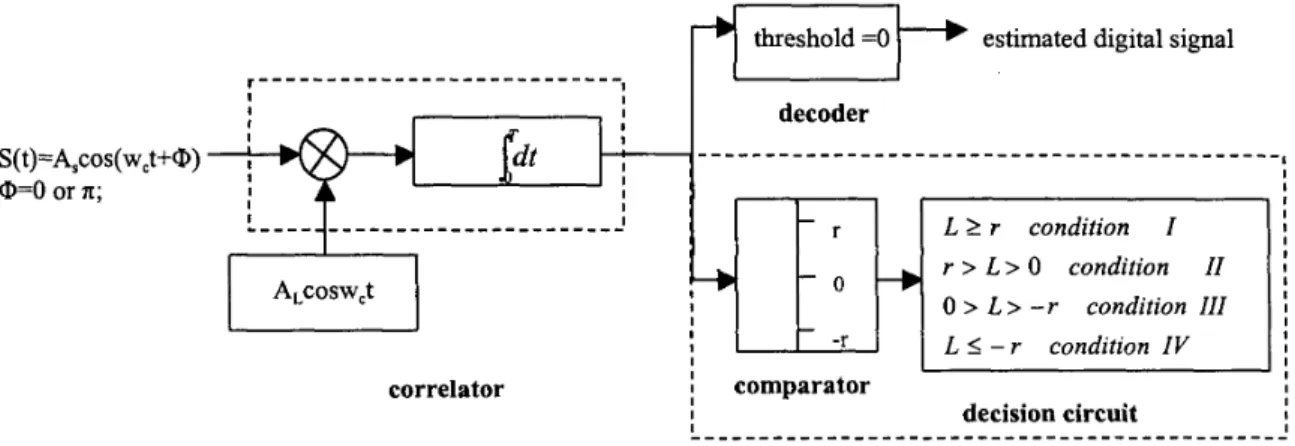
As shown in Fig 1, the proposed BPSK receiver with side information generation consists of two parts. The first one consists of a correlator and a maximum likellhood decoder to produce an estimated digital signal. The second one, which is connected to the output of the correlator, includes a comparator and a decision circuit to generate side information. The only difference between the conventional PSK receiver and our receiver is the side information generator that is designed to extract the side information of the input signal by marking the possible error bits. In the
'The work is supported by the National Science Council, R.0.C under the grant NSC 88-22 13-E-002-08 1.
S(t)=A,cos(w,t+@) O=O or I[; I I I I correlator
I
decoder I I r > L > 0 condition I 0 > L > - r condition III ! -r L 5 - r condition IV I Iside information generator
Fig 1: receiver diagram
first branch, the output value of the correlator is greater than the threshold level, the decision is made in favor of "1". Otherwise, the decision is made in favor of "0". If "1" is transmitted, the probability distribution of the correlator output is shown in Fig 2, where T is the bit duration, A,and A, are the amplitudes of the received signal and the local oscillator.
Fig 2: the distribution of the output value of correlator when "1" is sent by transmitter.
Now we consider the side information generation. It is obvious, if the output value of the correlator is larger than r, the transmitted signal has very high probability to be "1". If the output value of the correlator is fallen in the region ( 0 , r ) ,the signal will still be determined as "1" with slightly higher possibility of wrong decision. Similarly, if the output value of the correlator is fallen in the region ( 0, -r ), the bit will also have higher error probability. So all the received
signals in the regions ( r, CO), ( 0, r ), ( -r, 0), and ( -r, -00) will be recorded and denote as Conditions I, 11, I11 and IV for further processing. The bits in Conditions I1 and I11 will be specially marked. Obviously most error bits should be in the marked bits if we set the threshold r properly. When cells are transmitted, the receiver uses the CRC checksum to detect erroneous cells. With the aid of side information the receiver may locate the erroneous bits and correct them.
3. Error Correction Scheme with Side Information
In this paper, we assume that the channel is Rayleigh fading channel and the SR ARQ protocol is employed. For simplicity, the buffer is assumed to be infinite and the effect of erroneous acknowledgement (ACK) and negative
acknowledgement (NAK) is ignored. The length of packet is 53 bytes including 2 bytes CRC checksum. The format of packet is defined as shown in Fig 3.
Header
Payload
CRC
The side-information error correction scheme consists of n-bits-marked error correction and two-packet error correction. The protocol is described as below.
If
a packet is sent by the transmitter and received without error, the receiver will deliver it to the higher layer and send an ACK to the transmitter. If the packet is erroneous, n-bits-marked error correction will be employed. For example, if n bits of Conditions I1 and I11 in an erroneous packet and the error bits occur in the n marked bits. The sum of all combinations of the error bits is:w q
b2I
I1
I11
n,
=~ [ y ]
...
(1)
i=lI
I1
I11
IV
1
1
1
0
1
1
0
0
1
1
0
0
Therefore, we can correct the packet by alternating the n marked bits n, times at most. If the number of marked bits is larger than the maximum number of marked bits, a NAK will be sent to the sender immediately.
I
V
l
O
O
O
I I I I I
Tablel: error correction table of two-packet error correction
After the n-bits-marked error correction process, if the erroneous packet can be corrected, the receiver delivers it to the higher layer and sends an ACK back. Otherwise, the receiver saves the packet and sends a NAK to the transmitter to request for a retransmission. The receiver will process the retransmitted packet as the previous one, but it will not send the NAK back if it can't be corrected immediately. The receiver will further process the packet by employing two-
packet error correction which compares these two erroneous packets bit by bit. Table1 is the decision table of this process. b l and b2 denote the same position bits in the first packet and the retransmitted packet. For example, if the bit in the first packet was fallen in Condition I and the bit in the retransmitted packet was fallen in Condition
IV,
this bit will be determined as 'I 1 'I.If the packet still can not be corrected, the receiver will save the first retransmitted packet, discard the first transmitted one and send a NAK to the transmitter. When the receiver received the second retransmitted packed, it will
treat the packet as the first retransmitted one. This procedure will continue until the packet is received successfully. After some tedious derivation, we can express the throughput of this scheme as follows:
Throughput
= 1
/
E ,
...
.(
2)
E ,
= 1
+
(1 -
P j ) / ( P f
+
PEEc)
...
( 3)
P
-
P,
+
Pn
...
( 4 )
4
5 )
f -
...
P,
=(1 -
P,)”
nPn
=
CB[(P2
+
P 3 ) i 4 B - i
-
P 2 n 4 E - i ]
...
( 6 )
i=l...
PEEC
=
Pa/,
-
P,,
-
Pc2
-
Pnl
-
Pn2
+
PCl2
+
Pcln2
+
Pc2nl
+
Pn12
P,, = (1
- P, -
P 2 4 ) B
...
...( 9)
4 7 )
Pal/
=(1
- P,
-
P24+
P31)”...
...
( 8 )
~ , 2= ((1 -
p e l 2
+
~ 3 1 ) ” . . ....
...(
10)
-
(Cl
+
e2
+
43
+
4 4 ) B - i ( ~ 2 1
+
P~~
+
P ~ ~ ) ~ I
...
( 11)
n ‘n2 =‘:
[(41
+ ‘21+
‘31 )”-‘(‘I2+
‘13+
‘22+
23‘ i = l-
+
~ 2+
1~ 3)”-‘(42
1+
~ 2 2 111...
(
12)
PCl2
=(1 -
P,)’”
...
( 13)
nPcln2 =
CC,”[(P,,
+
P 2 1 ) B - i ( e 2
+
e3
+
P22
+
P23)i
-(el
+
P 2 , ) y e 2
+
P22)i]...
(14)
i=l n
...
=CC,”[(<,
+
< 2 ) B - i ( P 2 1
+
e2
+
<Ji-
+
< 2 ) B - i ( < l+
(1 5 )
i=l “-1 n n/
k!
(m,
-
k)!(rn2
-
k)!.
k = O m , = k + l m , = k[(e2
+
e3)*(e2
+
<3)m2-k(el
+
el)ml-k
-
(e2
+
43)k(<2
+
< 3 ) r n 2 - * & m l - k-
P22*<2m2
-*
(p21
+
-*
+
p 2 2 k < 2 m 2-kp21m’
-7
...
(1
6 )
Ay”
= x ! / ( x
-
y ) ! ,x 2 y
(1
7)
and
A...
A...
cy”
= x ! / [ ( x-
y ) ! y ! ]
, x
2y
(1
8)
where
Pf
is the probability of the first transmitted packet that is received successfully. PEEc is the probability of the error packet that can be recovered when the first transmitted packet and the first retransmitted packet were not receivedsuccessfully. E, is the average number of transmissions for a successful packet. P, is the bit error rate. B is the packet size. n is the maximum number of marked bits. P ,
,
P2 , P3 and P4 are the probabilities that the output values of the correlator is fallen in the regions ( r,a),
( 0, r ), ( -r, 0), and ( -r, -00) respectively. Pv is P*p, (‘XI and ‘y’ can be 1, 2 , 3 or4.)
4. Numerical Results and Discussion
In this section, we will show the results of the side-information error correction scheme. In Fig 4, it is obviously the performance is the best when the maximum number of the marked bits is ten (n=lO). Because we can correct the erroneous packet by n-bits-marked error correction scheme when the error bits are all in the marked bits. The larger n is the more possibility of the error bits is included in the marked bits. The maximum gain occurs when the BER is 2 . 6 ~ 1 0 ‘
’.
We define the gain as the difference of the throughputs of side-information error correction scheme and the conventional SR. Fig 5 depicts the throughput versus the average signal to noise ratio. The maximum gain occurs when average signal to noise ration is 20dB.0.7
0
1 o - ~ 1 o4 10” 10“ 10”
bit error rate
Fig4: throughput of sideinformation error correction (N=3,5,10)
1 - 0.9 0.8 0.7 0.6 g0.5
a
5
0.4 0.3 0.2 . . . c . .-
-
SR (Selective Repeat)---
side-information (N=3) . .... side-information (N=5)4
-.-. side-information (N=lO) . ni
U 10 20 30 40 50 60average signal to noise ratio (dB) Fig.5: ATM cell throughput
5.
Conclusion
A novel error correct scheme with the aid of physical layer side information is proposed and analyzed. This scheme is applicable for wireless ATM transmission over Rayleigh fading channel especially for time sensitive packets such as voice or video. The result shows that this scheme can improve the ATM throughput tremendously when the BER is between 10-*and
IO”
or the signal to noise ratio around 20dB. This scheme does not change the transmitter but requires modifying the receiver a little and needs computation power which can be solved as more powerful and low power comssuption processors are available.6.
References
[
11
Siavash M. Alamouti and Samir Kallel, ’Adaptive trellis-coded multiple-phase-shift keying of Rayleigh fading[2]
Michele Elia and Giorgio Taricco, ‘Soft decoding of Golay-coded PSK modulations over the Rayleigh fading channel’, IEEE Trans. Commun., vol. 42, no. 6, pp. 2305-2313, June 1994.[3]
Marc P. C. Fossorier and Shu Lin, ‘Soft decision decoding of linear block codes based on ordered statistics for the[4]
Monica Visintin, ‘Differential PSK block demodulation over a flat correlated Rayleigh-fading channel’, IEEE[5]
Shu Lin and PhilipS.
Yu, ’A hybrid ARQ scheme with parity retransmission for error control of satellite channels’,[6]
Shu Lin / Daniel J. costello , Jr. ,”Error Control Coding : Fundamentals and Applications” Prentice Hall, United[7]
AndrewS.
Tanenbaum, “Computer Networks”, Prentice Hall, New Jersey, third edition, 1996.[
81
Uyless Black, ”ATM: Foundation for Broadband Networks”, Prentice Hall, New Jersey, 1995.[
91
John G. Proakis,”Digital Communication”, Prentice Hall, Singapore, third edition, 1995.Rayleigh fading channel with coherent detection’, IEEE Trans. Commun. Vo1.45, no.1, pp. 12-14, Jan. 1997.
Trans. Commun. Vo1.45, no.1, pp. 9-1 1, Jan. 1997.
IEEE Trans. Commun. Vol. Com-30,n0.7, pp. 1701-1719, July 1982.