國 立 交 通 大 學
電子工程學系 電子研究所碩士班
碩 士 論 文
IEEE 802.16e OFDMA 同步技術之研究與數位訊號
處理器實現
Research in and DSP Implementation of Synchronization
Techniques for IEEE 802.16e
研 究 生: 劉耀鈞
指導教授: 林大衛 博士
IEEE 802.16e OFDMA 同步技術之研究與數位訊號處理器實現
Research in and DSP Implementation of Synchronization Techniques
for IEEE 802.16e
研 究 生: 劉耀鈞 Student: Yao Chun Liu
指導教授: 林大衛 博士 Advisor: Dr. David W. Lin
國 立 交 通 大 學
電子工程學系 電子研究所碩士班
碩 士 論 文
A Thesis
Submitted to Department of Electronics Engineering & Institute of Electronics College of Electrical and Computer Engineering
National Chiao Tung University in Partial Fulfillment of the Requirements
for the Degree of Master of Science
in
Electronics Engineering June 2007
Hsinchu, Taiwan, Republic of China
IEEE 802.16e OFDMA 同步技術之研究與數位訊號
處理器實現
研究生:劉耀鈞 指導教授:林大衛 博士
國立交通大學
電子工程學系 電子研究所碩士班
摘要
本篇論文介紹 IEEE 802.16e 正交分頻多工存取(OFDMA)裡,同步的問題、 演算法、以及實做方面的議題。 當一個行動電話在一開始要進入網路的時候,我們必須做起始的同步。在起 始的同步中,包含了符碼時間偏移、載波偏移和前置符元序號(preamble index) 需要同步。我們使用循環字首(cyclic prefix)的相關性(correlation)及在第一個下行 次訊框(subframe)裡的資訊來估計出較準確的符碼時間偏移和小數部分載波偏 移。之後我們在頻域上用補償之後的同步碼來聯合估計出整數載波偏移和前置符 元序號。我們利用前置符元序列和前置符元的特性來做估計,另外我們也介紹了 一些不同複雜度的方法。 在之後的次訊框中,行動電話只需要做到追蹤符碼時間偏移和小數部分載波 偏移。我們再次使用循環字首的相關性並在每個符元間利用指數平均來求得較準 確的結果。另外,因為我們在非起始的同步中,我們已經知道前置符元序號,因 此我們可利用這個資訊來估計符碼時間偏移。這個方法主要是利用前置符元序列
之間的準正交性的特性來估計。我們首先是用浮點數運算來驗證,並同時在可加 性白色高斯雜訊通道(AWGN)以及多路徑 Rayleigh 衰減通道下做模擬,模擬速度 高達 120 km/h,並觀察其結果。 最後,我們把這些方法修改成定點運算的版本,並在數位訊號處理平台上, 最佳化我們的程式的速度。雖然修改成定點運算會使效能衰減,但其結果依然可 以接受。經過最佳化之後,同步的工作都能達到即時處理(real time)的要求。
Research in and DSP Implementation of
Synchronization Techniques for IEEE 802.16e
Student: Yao Chun Liu Advisor: Dr. David W. Lin
Department of Electronics Engineering
Institute of Electronics
National Chiao Tung University
Abstract
This thesis introduces the synchronization problems, algorithms, and imple- mentation issues of IEEE 802.16e OFDMA system.
In DL synchronization, the (mobile station) MS receiver needs to perform initial synchronization upon its initial entrance to the network. There are timing offset, carrier frequency offset (CFO), and preamble index needed to be estimated during initial synchronization. We use the information of the first DL subframe to estimate the more accurate timing and fractional CFO by cyclic prefix (CP) correlation. Then, we consider the joint detection of integer CFO and preamble index using the compensated preamble in the frequency domain. The preamble sequences and the feature of preamble symbol are exploited and a number of detection methods of different complexity are introduced.
In subsequent subframe, the MS only needs to track the timing offset and fractional CFO. We use CP correlation with exponential average over the symbols in the subframe to obtain a more accurate estimation. Besides, we also afford a data-aided method to estimate the symbol timing since we already know the preamble index during normal synchronization. This method exploits the quasi-orthogonality among the preamble sequences. We verify our system in floating-point computation,
and simulate our system in both AWGN and multipath Rayleigh fading channel, which the speed is as high as 120 km/h, and see the performance.
In the end, we modified these methods into fixed-point version, and then optimize the speed of our programs on the digital signal processor (DSP) platform. Although the performance is degraded because of fixed-point modification, the results still can be accepted. After DSP optimization, the synchronization tasks can achieve the real-time requirement.
誌謝
這篇論文能夠順利完成,首先要感謝的人是我的指導教授林大衛老師,在兩 年的研究所生涯當中,由於老師的細心指導及在專業領域的博學精深,使得我學 習到不少研究的精神與方法。 此外,感謝通訊電子與訊號處理實驗室所有的成員,包含各位師長、同學、 學長姐與學弟妹們。感謝洪崑健學長、吳俊榮學長和林鴻志學長給予我在研究過 程上的指導與建議,還有柏昇、政達、介遠、依翎、凱庭、志岡、錫祺、怡禎等 同學,因為能和你們共同討論、分享求學的經驗及一路上的相互扶持,讓這兩年 的研究生涯充滿歡樂與回憶。 最後,我要感謝我的家人們,感謝他們一直都在背後支持我,在求學過程中 總是不斷的鼓勵我,是我精神上最大的支柱。 在此,將此篇論文獻給所有幫助過我,陪伴我走過這一段歲月的師長,同學, 朋友與家人。 劉耀鈞 民國九十六年六月 於新竹Contents
1 Introduction 1
2 Overview of the IEEE 802.16e OFDMA Standard 3
2.1 Introduction to OFDM [3] . . . 3
2.2 Introduction to OFDMA . . . 5
2.3 Introduction to IEEE 802.16e . . . 8
2.3.1 OFDMA Basic Terms . . . 9
2.3.2 OFDMA Symbol Parameters . . . 10
2.3.3 Scalable OFDMA [7] . . . 11
2.4 OFDMA Frame Structure . . . 12
2.5 OFDMA Subcarrier Allocation . . . 16
2.5.1 Downlink . . . 17
2.5.2 Uplink . . . 20
2.6 Modulation . . . 23
2.7 Transmit Spectral Mask . . . 24
2.8 Frequency and Timing Requirements . . . 25
3 Introduction to the DSP Implementation Platform 27 3.1 The DSP Card [11] . . . 27
3.2 The DSP Chip [12] . . . 28
3.2.1 Central Processing Unit . . . 30
3.2.2 Memory Architecture and Peripherals . . . 32
3.3.1 Code Composer Studio . . . 33
3.3.2 Code Development Flow [16] . . . 34
3.4 Code Optimization on TI DSP Platform . . . 35
3.4.1 Compiler Optimization Options [16] . . . 35
3.4.2 Software Pipelining [17] . . . 38
3.4.3 Intrinsics [16] . . . 38
4 Transmission Environment and Transmission Filtering 40 4.1 System Parameters . . . 40
4.2 Channel Environments . . . 41
4.2.1 Gaussian Noise . . . 41
4.2.2 Slow Fading Channel . . . 41
4.2.3 Fast Fading Channel . . . 42
4.2.4 Power-Delay Profile Model . . . 42
4.3 Transmission Filtering . . . 43
5 Synchronization Techniques for IEEE 802.16e OFDMA 49 5.1 OFDMA Synchronization Problems and Techniques . . . 49
5.1.1 Initial DL Synchronization . . . 52
5.1.2 Normal DL Synchronization . . . 59
5.1.3 UL Synchronization . . . 61
5.2 Floating-Point Simulation Results . . . 61
5.2.1 Symbol Timing Estimation . . . 61
5.2.2 Fractional CFO Estimation . . . 67
5.2.3 Integer CFO Estimation and Preamble Index Identification . . . . 68
6 Fixed-Point DSP Implementation 76 6.1 Fixed-Point Implementation . . . 76
6.1.1 Modulation and Subcarrier Allocation . . . 77
6.1.2 IFFT, FFT and SRRC Filter . . . 78
6.2 DSP Optimization . . . 79
6.2.1 The IFFT and FFT . . . 79
6.2.2 Synchronization . . . 79
6.3 Fixed-Point Simulation Results . . . 83
6.3.1 Symbol Timing Estimation . . . 83
6.3.2 Fractional CFO Estimation . . . 83
6.3.3 Integer CFO Estimation and Preamble Index Identification . . . . 84
6.4 DSP Optimization Results . . . 87
7 Conclusion and Future Work 93 7.1 Conclusion . . . 93
List of Figures
2.1 Bandwidth efficiency comparison of traditional FDM and OFDM systems. 4
2.2 The use of cyclic prefix (from [5]). . . 5
2.3 Comparison of subcarrier allocatins in OFDM and OFDMA (from [6]). . 6
2.4 Subcarrier allocation in an OFDMA symbol (from [7]). . . 7
2.5 OFDMA frequency description (3-channel schematic example, from [1]). 9 2.6 Example of the data region which defines the OFDMA allocation (from [1]). . . 10
2.7 Example of an OFDMA frame (with only mandatory zone) in TDD mode (from [2]). . . 13
2.8 Illustration of OFDMA with multiple zones (from [2]). . . 14
2.9 FCH subchannel allocation for all 3 segments (from [1]). . . 15
2.10 Example of DL renumbering the allocated subchannels for segment 1 in PUSC (from [1]). . . 16
2.11 DL cluster structure (from[10]). . . 19
2.12 Description of an UL tile (from [10]). . . 22
2.13 PRBS generator for pilot modulation (from [2]). . . 23
2.14 Transmit spectral mask for license-exempt operation (from [1]). . . 26
3.1 Sundance’s SMT395 module . . . 28
3.2 Functional block and CPU (DSP core) diagram [13]. . . 30
3.3 Code development cycle [15]. . . 33
3.4 Code development flow for C6000 (from [16]). . . 36
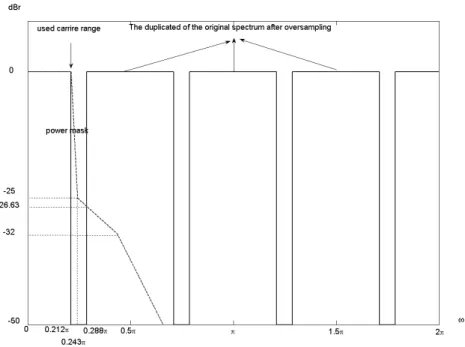
4.1 Frequency spectrum of the signal after 4 times oversampling and relation
to the power mask. . . 46
4.2 Impulse response of the SRRC filter (solid) and the convolution of the impulse responses of two SRRC filters (dashed) [21]. . . 47
4.3 Magnitude responses of three different SRRC filters. . . 47
4.4 Magnitude responses of 49-taps SRRC filter with roll-off factor 0.15. . . . 48
4.5 Spectral density of the signal after the interpolation and SRRC filtering, compared to the spectral mask. . . 48
5.1 The symbol time offset requirement (from [22]). . . 51
5.2 Structure of initial DL synchronization. . . 52
5.3 Structure of J.-C. Lin’s symbol timing and fractional carrier frequency synchronization method [29]. . . 53
5.4 Structure of normal DL synchronization. . . 58
5.5 Structure of UL synchronization. . . 61
5.6 Distribution of timing offset estimation errors. . . 63
5.7 Symbol time synchronization error distribution under different SNRs (ini-tial synchronization). . . 64
5.8 Symbol time synchronization error distribution under different SNRs (nor-mal synchronization). . . 65
5.9 RMSE of symbol timing offset synchronization for Vehicular A channel. . 66
5.10 Error distributions of two algorithms during normal synchronization. . . . 67
5.11 Error distributions at different speeds in Vehicular A channel. . . 68
5.12 Error distributions of data-aided method and modified data-aided method during normal synchronization. . . 69
5.13 RMSE of fractional CFO under AWGN channel. . . 70
5.14 RMSE of fractional CFO under SUI3 channel. . . 72
5.15 Fractional CFO synchronization error distribution under different SNRs. . 73
5.16 Error probability in either the identified preamble index or the estimated integer CFO under Vehicular A channel, where FFT size = 1024. . . 74
5.17 Error probability in either the identified preamble index or the estimated
integer CFO under SUI3 channel, where FFT size = 1024. . . 74
5.18 Error probability in either the identified preamble index or the estimated integer CFO under Vehicular A channel, where FFT size = 2048. . . 75
6.1 Fixed-point data formats used at different points in the transmitter. . . 77
6.2 Fixed-point data formats used at different points in the receiver. . . 78
6.3 A part of C code for compensation function. . . 80
6.4 A part of assembly code for compensation function-I. . . 81
6.5 A part of assembly code for compensation function-II. . . 82
6.6 RMSE of symbol timing offset estimation in AWGN with fixed-point and floating-point implementation. . . 84
6.7 Symbol time synchronization error distribution under different SNRs (ini-tial synchronization). . . 85
6.8 Symbol time synchronization error distribution under different SNRs (nor-mal synchronization). . . 86
6.9 RMSE of fractional CFO estimation in AWGN with fixed-point and floating-point implementation. . . 87
6.10 RMSE of fractional CFO under SUI3 channel for FFT size 2048 with bandwidth 20 MHz. . . 88
6.11 RMSE of fractional CFO under SUI3 channel for FFT size 2048 with bandwidth 10 MHz. . . 89
6.12 Fractional CFO synchronization error distribution under different SNRs. . 90
6.13 Error probability in either the identified preamble index or the estimated integer CFO with fixed-point and floating-point implementation under Ve-hicular A channel. . . 91
List of Tables
2.1 OFDM Advantages and Disadvantages . . . 5
2.2 S–OFDMA Parameters Proposed by WiMAX Forum . . . 12
2.3 1024-FFT OFDMA DL Carrier Allocation for PUSC . . . 18
2.4 1024-FFT OFDMA UL Carrier Allocation for PUSC . . . 21
2.5 Transmit Sprctral Mask for License-Exempt Bands . . . 25
3.1 Functional Units and Operations Performed [12] . . . 31
4.1 System Parameters Used in Our Study . . . 41
4.2 Terrain Type vs. SUI Channels . . . 43
4.3 General characteristics of SUI channels . . . 43
4.4 SUI-1 Channel Model . . . 44
4.5 SUI-2 Channel Model . . . 44
4.6 SUI-3 Channel Model . . . 44
4.7 SUI-4 Channel Model . . . 45
4.8 SUI-5 Channel Model . . . 45
4.9 SUI-6 Channel Model . . . 45
4.10 ETSI “Vehicular A” Channel Model in Different Units [20] . . . 46
5.1 OFDMA Receiver SNR Assumptions [2] . . . 62
5.2 Computational Complexity for Integer CFO Estimation and Preamble In-dex Identification . . . 75
6.1 Ranges of Modulated Signal Values . . . 77
Chapter 1
Introduction
The IEEE 802.16e, of which a subset is commonly known as Mobile WiMAX (World-wide Interoperability of Microwave Access), is a broadband wireless access (BWA) sys-tem which has drawn much attention these days. IEEE 802.16e is originally suggested as an enhancement version of IEEE Std. 802.16-2004 to provide mobile station (MS) with mobility at vehicular speed. Therefore, it specifies BWA systems for both fixed and mobile MS simultaneously [1],[2].
One of the most promising modes in the IEEE 802.16e standard is the Orthogonal Frequency Division Multiple Access (OFDMA) mode, which is generally accepted as a performance efficient multiple access scheme. The Mobile WiMAX system also utilizes the bandwidth scalability, where the FFT size typically increases with the bandwidth. In this thesis, we consider the IEEE 802.16e WirelessMAN OFDMA system with a time-division duplex (TDD) mode, where downlink (DL) and uplink (UL) transmissions are time multiplexed in each TDD frame.
Our study can be divided into two parts. The first part is the synchronization tech-niques for IEEE 802.16e OFDMA. Synchronization in OFDMA system involves fre-quency and timing recovery. For operation under the current IEEE 802.16e OFDMA TDD specifications, the identification of the preamble index may also be considered part of the synchronization process. Therefore, in the present study we consider carrier fre-quency synchronization, timing synchronization, and preamble index identification, for both fixed and mobile communication channels.
The second part is the digital signal processor (DSP) implementation of the synchro-nization techniques. We implement them on Texas Instrument (TI)’s DSP. Moreover, we employ various optimization techniques to accelerate the execution speed of the programs in the DSP implementation.
This thesis is organized as follows. We first introduce the IEEE 802.16e Wireless-MAN OFDMA standard in chapter 2. Chapter 3 introduces the DSP implementation platform. In chapter 4, the system parameters and channel environments are discussed. The transmission filtering is also analyzed in chapter 4. We analyze the synchronization problems and present some solutions in chapter 5. Chapter 6 discusses the DSP optimiza-tion methods and presents the optimizaoptimiza-tion results. Finally, the conclusion is given in chapter 7, where we also point out some potential future work.
Chapter 2
Overview of the IEEE 802.16e OFDMA
Standard
In this chapter, we first introduce some basic concepts regarding OFDM and OFDMA. Then we give an overview of the IEEE 802.16e OFDMA standard. For the sake of sim-plicity, we only introduce the specifications that have use in our study. Other specifica-tions like channel coding, MAP messages, transmit diversity, etc., are not our concern and are ignored in this introduction. For more details we refer the readers to [1] and [2], from which we take much of the material in this chapter.
2.1 Introduction to OFDM [3]
OFDM is a special case of multicarrier transmission technique, where a single datastream is transmitted over a number of subcarriers a lower rates. The concept of OFDM is to use parallel data transmission and frequency multiplexing. It divides the available spectrum into narrower subcarrier bands, and each subcarrier only transmits a portion of the total information.
The orthogonality of OFDM constitutes one major difference from the classical par-allel data system, making its use of the available spectrum more efficient. Figure 2.1 shows the difference. As we can see, the subcarriers in an OFDM symbol can be arranged so that the sideband of each subcarrier overlaps but the received symbols still live
with-Figure 2.1: Bandwidth efficiency comparison of traditional FDM and OFDM systems. out adjacent-carrier interference. This can be accomplished by using the discrete Fourier transform (DFT) proposed by Weinstein and Ebert in 1971 [4]. The complexity of DFT, however, is too expensive. Fortunately, modern advances in very-large-scale integration (VLSI) make it possible to use the fast Fourier transform (FFT) for a more efficient im-plementation of the DFT. The complexity is reduced from N2 in DFT to N log
2N in
FFT.
One of the main reasons to use OFDM is to increase the robustness against frequency selective fading or narrowband interference. An OFDM system may encode data using forward error correction (FEC) coding and distribute them across several subcarriers. If frequency-selective fading causes errors in the reception of few subcarriers, the data bits in those subcarriers are recovered through FEC.
Another reason for choosing OFDM is its natural immunity to multipath. For a given overall data rate, the increasing number of carriers due to overlapping can reduce the data rate that each individual carriers must convey, and hence lengthen the symbol period. This means that the inter symbol interference (ISI) affects a smaller percentage of each symbol. Therefore complex equalization is normally not needed in the receiver.
In order to eliminate the ISI completely, a guard time (or guard interval, or cyclic pre-fix) is inserted. The guard time is chosen larger than the expected delay spread, such that
Figure 2.2: The use of cyclic prefix (from [5]).
multipath components from one symbol cannot interfere with the next symbol. However, if we insert zeros within the guard interval, the orthogonality among subcarriers will no longer exist, which causes serious intercarrier interference (ICI). To preserve the orthog-onality among the subcarriers and eliminate ICI, the OFDM symbol should be cyclically extended in the guard time rather than just extended with zero. Figure 2.2 shows how to add cyclic prefix in front of an OFDM symbol. Hence if the maximum multipath delay is smaller than the guard time, there will not be ISI or ICI.
Finally, the advantages and disadvantages are summarized in Table 2.1. The advan-tages are already discussed above. The first two disadvanadvan-tages will be considered in this thesis, while the last two are ignored.
2.2 Introduction to OFDMA
OFDMA is a multiple access method based on OFDM signaling that allows simultaneous transmissions to and from multiple users along with the other advantages of OFDM. In
Table 2.1: OFDM Advantages and Disadvantages
Advantages
Disadvantages
Bandwidth efficiency Sensitive to frequency offset Immunity to multipath effect Sensitive to timing offset Robust against narrowband interference Sensitive to phase noise
Figure 2.3: Comparison of subcarrier allocatins in OFDM and OFDMA (from [6]). OFDM, a channel is divided into carriers which is used by one user at any time. In OFDMA, the carriers are divided into subchannels. Each subchannel has multiple carriers that form one unit in frequency allocation. In this way, the bandwidth can be allocated dynamically to the users according to their needs. A simple comparison of the subcarrier allocation of OFDM and OFDMA is shown in Fig. 2.3.
An additional advantage of OFDMA is the following. Due to the large variance in a mobile system’s path loss, inter-cell interference is a common issue in mobile wireless systems. An OFDMA system can be designed such that subchannels can be composed from several distinct permutations of subcarriers. This enables significant reduction in inter-cell interference when the system is not fully loaded, because even on occasions where the same subchannel is used at the same time in two different cells, there is only a partial collision on the active sub-carriers.
Figure 2.4: Subcarrier allocation in an OFDMA symbol (from [7]).
response of a typical broadband wireless channel is also depicted. In this example, the deep-fading condition and narrowband interference are considered. In the top plot, we see that when the channel is in deep fade, the subcarriers are not sufficiently energy efficient to carry information. These wasted subcarriers can be utilized by there uses in OFDMA, thus achieving higher efficiency and capacity. Very few, if any, subcarriers are likely to be wasted in OFDMA, since no particular subcarrier is likely to be bad for all users.
In order to support multiple users, the control mechanism becomes more complex. Besides, the OFDMA system has some implementation issues which are more compli-cated to handle. For example, power control is needed for the uplink to make signals
from different users have equal power at the receiver, and all users have to adjust their transmitting time to be aligned. We shall address some issues in the context of IEEE 802.16e.
2.3 Introduction to IEEE 802.16e
Since the publication of the IEEE 802.16 standard for fixed broadband wireless access in 2001, a number of revision and amendments have taken place. Like other IEEE 802 standards, the 802.16 standards are primarily concerned with physical (PHY) layer and medium access control (MAC) layer functionalities. The idea originally was to provide broadband wireless access to buildings through external antennas communicating with radio base stations (BSs).
To overcome the disadvantage of the line-of-sight (LOS) requirement between trans-mitters and receivers in the 802.16 standard, the 802.16a standard was approved in 2003 to support nonline-of-sight (NLOS) links, operational in both licensed and unlicensed fre-quency bands from 2 to 11 GHz, and subsequently revised to create the 802.16d standard (now code-named 802.16-2004). With such enhancements, the 802.16-2004 standard has been viewed as a promising alternative for providing the last-mile connectivity by radio link. However, the 802.16-2004 specifications were devised primarily for fixed wireless users. The 802.16e task group was subsequently formed with the goal of extending the 802.16-2004 standard to support mobile terminals.
The IEEE 802.16e has been published in Febuary 2006. It specifies four air inter-faces: WirelessMAN-SC PHY, WirelessMAN-SCa PHY, WirelessMAN-OFDM PHY, and WirelessMAN-OFDMA PHY. This study is concerned with WirelessMAN-OFDMA PHY in a mobile communication environment.
Some glossary we will often use in the following is as follows. The direction of transmission from the base station (BS) to the subscriber station (SS) is called downlink (DL), and the opposite direction is uplink (UL). The SS is considered synonymous as the mobile station (MS). It is sometimes termed the user. The BS is a generalized equipment set providing connectivity, management, and control of the SS.
2.3.1 OFDMA Basic Terms
In the OFDMA mode, the active subcarriers are divided into subsets of subcarriers, where each subset is termed a subchannel. The subcarriers forming one subchannel may, but need not be, adjacent. The concept is shown in Fig. 2.5.
Three basic types subchannel organization are defined: partial usage of subchannels (PUSC), full usage of subchannels (FUSC), and adaptive modulation and coding (AMC); among which the PUSC is mandatory and the other two are optional. In PUSC DL, the entire channel bandwidth is divided into three segments to be used separately. The FUSC is employed only in the DL and it uses the full set of available subcarriers so as to maximize the throughput.
Slot and Data Region
The definition of an OFDMA slot depends on the OFDMA symbol structure, which varies for uplink and downlink, for FUSC and PUSC, and for the distributed subcarrier permu-tations and the adjacent subcarrier permutation.
• For downlink PUSC using the distributed subcarrier permutation, one slot is one subchannel by two OFDMA symbols.
• For uplink PUSC using either of the distributed subcarrier permutations, one slot is one subchannel by three OFDMA symbols.
• For downlink FUSC and downlink optional FUSC using the distributed subcarrier permutation, one slot is one subchannel by one OFDMA symbol.
In OFDMA, a data region is a two-dimensional allocation of a group of contiguous sub-channels, in a group of contiguous OFDMA symbols. All the allocations refer to logical subchannels. This two-dimensional allocation may be visualized as a rectangle, such as the 4×3 rectangle shown in Fig. 2.6.
Segment
A segment is a subdivision of the set of available OFDMA subchannels (that may include all available subchannels). One segment is used for deploying a single instance of the MAC.
Permutation Zone
A permutation zone is a number of contiguous OFDMA symbols, in the DL or the UL, that use the same permutation formula. The DL subframe or the UL subframe may con-tain more than one permutation zone. The concept of permutation zone will be further elaborate later.
2.3.2 OFDMA Symbol Parameters
Some OFDMA symbol parameters are listed below. • BW : Nominal channel bandwidth.
• Nused: Number of used subcarriers.
• n: Sampling factor. This parameter, in conjunction with BW and Nused, determines
the subcarrier spacing and the useful symbol time. • G: Ratio of cyclic prefix (CP) time to useful time. • NF F T: Smallest power of two greater than Nused.
• Sampling frequency: Fs = bn · BW/8000c × 8000.
• Subcarrier spacing: ∆f = Fs/NF F T.
• Useful symbol time: Tb = 1/∆f .
• Cyclic prefix (CP) time: Tg = G · Tb.
• OFDM symbol time: Ts= Tb+ Tg.
• Sampling time: Tb/NF F T.
2.3.3 Scalable OFDMA [7]
One feature of the IEEE 802.16e OFDMA is the selectable FFT size, from 128 to 2048 in multiples of 2, excluding 256 to be used with OFDM. This has been termed scalable OFDMA (S-OFDMA). One use of S-OFDMA is that if the channel bandwidths are allo-cated based on integer power of 2 times a base bandwidth, then one may consider making the FFT size proportional to the allocated bandwidth so that all systems are based on the same subcarrier spacing and the same OFDMA symbol duration, which may simplify system design. For example, Table 2.2 lists some S-OFDMA parameters proposed by the WiMAX Forum [8]. S-OFDMA supports a wide range of bandwidth to flexibly address the need for various spectrum allocation and usage model requirements.
When designing OFDMA wireless systems the optimal choice of the number of sub-carriers per channel bandwidth is a tradeoff between protection against multipath, Doppler shift, and design cost/coplexity. Increasing the number of subcarriers leads to better im-munity to the ISI caused by multipath; on the other hand it increases the cost and com-plexity of the system (it leads to higher requirements for signal processing power and
Table 2.2: S–OFDMA Parameters Proposed by WiMAX Forum
Parameters
Values
System Channel Bandwidth (MHz) 1.25 5 10 20 Sampling Frequency (MHz) 1.4 5.6 11.2 22.4 FFT Size 128 512 1024 2048 Subcarrier Spacing (∆f ) 10.94 kHz
Useful Symbol Time (Tb=1/∆f ) 91.4 µsec
Guard Time (Tg=Tb/8) 11.4 µsec
OFDMA Symbol Duration (Ts=Tb+Tg) 102.9 µsec
power amplifiers with the capability of handling higher peak-to-average power ratios). Having more subcarriers also results in narrower subcarrier spacing and therefore the sys-tem becomes more sensitive to Doppler shift and phase noise. Calculations show that the optimum tradeoff for mobile systems is achieved when subcarrier spacing is about 11 kHz [9] .
2.4 OFDMA Frame Structure
Duplexing Modes
In licensed bands, the duplexing method shall be either frequency-division duplex (FDD) or time-division duplex(TDD). FDD SSs may be half-duplex FDD (H-FDD). In license-exempt bands, the duplexing method shall be TDD.
Point-to-Multipoint (PMP) Frame Structure
When implementing a TDD system, the frame is composed of BS and SS transmissions. Figure 2.7 shows an example. Each frame in the downlink transmission begins with a preamble followed by a DL transmission period and an UL transmission period. In each frame, time gaps, denoted transmit/receive transition gap (TTG) and receive/transmit gap (RTG), are between the downlink and uplink subframes and at the end of each frame,
Figure 2.7: Example of an OFDMA frame (with only mandatory zone) in TDD mode (from [2]).
respectively placed. They allow transitions between transmission and reception functions. Subchannel allocation in the downlink may be performed with PUSC where some of the subchannels are allocated to the transmitter or FUSC where all subchannels are allo-cated to the transmitter. The downlink frame shall start in PUSC mode with no transmit diversity. The FCH shall be transmitted using QPSK rate 1/2 with four repetitions using the mandatory coding scheme (i.e., the FCH information will be sent on four subchan-nels with successive logical subchannel numbers) in a PUSC zone. The FCH contains the DL Frame Prefix which specifies the length of the DL-MAP message that immediately follows the DL Frame Prefix and the repetition coding used for the DL-MAP message.
The transitions between modulations and coding take place on slot boundaries in time domain (except in AAS zone, where AAS stands for adaptive antenna system) and on sub-channels within an OFDMA symbol in frequency domain. The OFDMA frame may in-clude multiple zones (such as PUSC, FUSC, PUSC with all subchannels, optional FUSC, AMC, TUSC1, and TUSC2, where AMC stands for adaptive modulation and coding, and TUSC stands for tile usage of subchannels), the transition between zones is indicated in
Figure 2.8: Illustration of OFDMA with multiple zones (from [2]).
the DL-Map. Figure 2.8 depicts an OFDMA frame with multiple zones.
The PHY parameters (such as channel state and interference levels) may change from one zone to the next.
The maximum number of downlink zones is 8 in one downlink subframe. For each SS, the maximum number of bursts to decode in one downlink subframe is 64. This includes all bursts without connection identifier (CID) or with CIDs matching the SS’s CIDs. Allocation of Subchannels for FCH and DL-MAP, and Logical Subchannel Number-ing
In PUSC, any segment used shall be allocated at least the same number of subchannels as in subchannel group #0. For FFT sizes other than 128, the first 4 slots in the downlink part of the segment contain the FCH as defined before. These slots contain 48 bits modulated by QPSK with coding rate 1/2 and repetition coding of 4. For FFT-128, the first slot in the downlink part of the segment is dedicated to FCH and repetition is not applied. The basic allocated subchannel sets for segments 0, 1, and 2 are subchannel groups #0, #2, and #4, respectively. Figure 2.9 depicts this structure.
After decoding the DL Frame Prefix message within the FCH, the SS has the knowl-edge of how many and which subchannels are allocated to the PUSC segment. In order
Figure 2.9: FCH subchannel allocation for all 3 segments (from [1]).
to observe the allocation of the subchannels in the downlink as a contiguous allocation block, the subchannels shall be renumbered. The renumbering, for the first PUSC zone, shall start from the FCH subchannels (renumbered to values 0–11), then continue num-bering the subchannels in a cyclic manner to the last allocated subchannel and from the first allocated subchannel to the FCH subchannels. Figure 2.10 gives an example of such renumbering for segment 1.
For uplink, in order to observe the allocation of the subchannels as a contiguous allo-cation block, the subchannels shall be renumbered, and the renumbering shall start from the lowest numbered allocated subchannel (renumbered to value 0), up to the highest numbered allocated subchannel, skipping nonallocated subchannels.
The DL-MAP of each segment shall be mapped to the slots allocated to the segment in a frequency first order, starting from the slot after the FCH (subchannel 4 in the first symbol, after renumbering), and continuing to the next symbols if necessary. The FCH of segments that have no subchannels allocated (unused segments) will not be transmitted,
Figure 2.10: Example of DL renumbering the allocated subchannels for segment 1 in PUSC (from [1]).
and the respective slots may be used for transmission of MAP and data of other segments.
2.5 OFDMA Subcarrier Allocation
As mentioned, the OFDMA PHY defines four scalable FFT sizes: 2048, 1024, 512, and 128. For convenience, here we only take the 1024-FFT OFDMA subcarrier allocation for introduction. The subcarriers are divided into three types: null (guard band and DC), pilot, and data. Subtracting the guard tones from NF F T, one obtains the set of “used”
subcarriers Nused. For both uplink and downlink, these used subcarriers are allocated to
pilot subcarriers and data subcarriers. However, there is a difference between the differ-ent possible zones. For FUSC and PUSC, in the downlink, the pilot tones are allocated first; what remains are data subcarriers, which are divided into subchannels that are used
exclusively for data. Thus, in FUSC, there is one set of common pilot subcarriers, and in PUSC downlink, there is one set of common pilot subcarriers in each major group, but in PUSC uplink, each subchannel contains its own pilot subcarriers.
2.5.1 Downlink
Preamble
The first symbol of the downlink transmission is the preamble. There are three types of preamble carrier-sets, which are defined by allocation of different subcarriers for each one of them. The subcarriers are modulated using a boosted BPSK modulation with a specific pseudo-noise (PN) code. The preamble carrier-sets are defined using
P reambleCarrierSetn= n + 3 · k (2.1)
where:
P reambleCarrierSetn
n k
specifies all subcarriers allocated to the specific preamble, is the number of the preamble carrier-set indexed 0–2, is a running index 0–283.
For the preamble symbol there are 86 guard band subcarriers on the left side and the right side of the spectrum. Each segment uses a preamble composed of a carrier-set out of the three available carrier-sets in the manner that segment i uses preamble carrier-set i, where i = 0, 1, 2. Therefore, each segment eventually modulates each third subcarrier. In the case of segment 0, the DC carrier will be zeroed and the corresponding PN number will be discarded.
The 114 different PN series modulating the preamble carrier-set are defined in Table 309 of [1] for the 1024-FFT mode. The series modulated depends on the segment used and the IDcell parameter.
Symbol Structure for PUSC
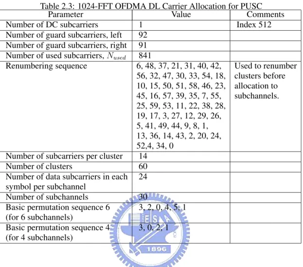
The symbol is first divided into basic clusters and zero carriers are allocated. Pilots and data carriers are allocated within each cluster. Table 310 of [2] summarizes the parameters
Table 2.3: 1024-FFT OFDMA DL Carrier Allocation for PUSC Parameter Value Comments Number of DC subcarriers 1 Index 512 Number of guard subcarriers, left 92
Number of guard subcarriers, right 91 Number of used subcarriers, Nused 841
Renumbering sequence 6, 48, 37, 21, 31, 40, 42, Used to renumber 56, 32, 47, 30, 33, 54, 18, clusters before 10, 15, 50, 51, 58, 46, 23, allocation to 45, 16, 57, 39, 35, 7, 55, subchannels. 25, 59, 53, 11, 22, 38, 28, 19, 17, 3, 27, 12, 29, 26, 5, 41, 49, 44, 9, 8, 1, 13, 36, 14, 43, 2, 20, 24, 52,4, 34, 0
Number of subcarriers per cluster 14 Number of clusters 60 Number of data subcarriers in each 24 symbol per subchannel
Number of subchannels 30
Basic permutation sequence 6 3, 2, 0, 4, 5, 1 (for 6 subchannels)
Basic permutation sequence 4 3, 0, 2, 1 (for 4 subchannels)
of the symbol structure of different FFT sizes for PUSC mode. Here we only take the 1024-FFT OFDMA downlink carrier allocation for example, which is summarized in Table 2.3. Fig. 2.11 depicts the DL cluster structure.
Downlink Subchannels Subcarrier Allocation in PUSC
The subcarrier allocation to subchannels is performed using the following procedure: 1. Dividing the subcarriers into the number of clusters (Nclusters), where the physical
clusters contain 14 adjacent subcarriers each (starting from carrier 0). The number of clusters varies with the FFT size.
Figure 2.11: DL cluster structure (from[10]). LogicalCluster =
RenumberingSequence(P hysicalCluster), first DL zone, or Use All SC indicator = 0 in STC DL Zone IE,
RenumberingSequence((P hysicalCluster)+ otherwise. 13 · DL P ermBase)modNclusters,
(2.2) In the first PUSC zone of the downlink (first downlink zone) and in a PUSC zone defined by STC DL ZONE IE() with “use all SC indicator = 0”, the default re-numbering sequence is used for logical cluster definition. For all other cases DL PermBase parameter in the STC DL Zone IE() or AAS DL IE() shall be used.
3. Allocating logical clusters to groups. The allocation algorithm varies with FFT size. For FFT size = 1024, dividing the clusters into six major groups. Group 0 includes clusters 0–11, group 1 clusters 12–19, group 2 clusters 20–31, group 3 clusters 32–39, group 4 clusters 40–51, and group 5 clusters 52–59. These groups may be allocated to segments; if a segment is used, then at least one group shall be allocated to it. By default group 0 is allocated to sector 0, group 2 to sector 1, and group 4 to sector 2.
4. Allocating subcarriers to subchannels in each major group, which is performed sep-arately for each OFDMA symbol by first allocating the pilot carriers within each cluster, and then partitioning all remaining data carriers into groups of contiguous subcarriers. Each subchannel consists of one subcarrier from each of these groups. The number of groups is therefore equal to the number of subcarriers per
subchan-nel, and it is denoted Nsubcarriers. The number of the subcarriers in a group is equal
to the number of subchannels, and it is denoted Nsubchannels. The number of data
subcarriers is thus equal to Nsubcarriers· Nsubchannels. The parameters vary with FFT
sizes. For FFT size = 1024, use the parameters from Table 2.3, with basic permuta-tion sequence 6 for even numbered major groups and basic permutapermuta-tion sequence 4 for odd numbered major groups, to partition the subcarriers into subchannels con-taining 24 data subcarriers in each symbol. The exact partitioning into subchannels is according to the permutation formula:
subcarrier(k, s) = Nsubchannels· nk
+{ps[nkmod Nsubchannels] + DL P ermBase} mod Nsubcahnnels (2.3)
where: subcarrier(k, s) s nk Nsubchannels ps[j] DL P ermBase
is the subcarrier index of subcarrier k in subchannel s,
is the index number of a subchannel, from the set {0,..., Nsubcarriers− 1},
= (k + 13 · s) mod Nsubcarriers, where k is the
subcarrier-in-subchannel index from the set {0,..., Nsubcarriers− 1},
is the number of subchannels (for PUSC use number of sub-channels in the currently partitioned major group),
is the series obtained by rotating basic permutation sequence cyclically to the left s times,
is an integer ranging from 0 to 31, which is set to the preamble IDCell in the first zone and determined by the DL-MAP for other zones.
On initialization, an SS must search for the downlink preamble. After finding the pream-ble, the user shall know the IDcell used for the data subchannels.
2.5.2 Uplink
The UL follows the DL model, therefore it also supports up to three segments. The UL supports 35 subchannels where each transmission uses 48 data subcarriers as the
minimal block of processing. Each new transmission for the uplink commences with the parameters as given in Table 2.4.
Symbol Structure for Subchannel (PUSC)
A slot in the uplink is composed of three OFDMA symbols and one subchannel. Within each slot, there are 48 data subcarriers and 24 fixed-location pilots. The subchannel is constructed from six uplink tiles, each tile has four successive active subcarriers and its configuration is illustrated in Fig. 2.12.
Partitioning of Subcarriers into Subchannels in the Uplink
The usable subcarriers in the allocated frequency band shall be divided into Ntilesphysical
tiles as defined in Fig. 2.12 with parameters from Table 2.4. The allocation of physical tiles to logical tiles in subchannels is performed in the following manner:
T iles(s, n) = Nsubchannels·n+{Pt[(s+n) mod Nsubchannels]+UL P ermBase} mod Nsubcahnnels
(2.4) Table 2.4: 1024-FFT OFDMA UL Carrier Allocation for PUSC
Parameter Value Comments Number of DC subcarriers 1 Index 512
Nused 841
Guard subcarriers: left, right 92,91
TilePermutation 11, 19, 12, 32, 33, 9, 30, 7, used to allocate 4, 2, 13, 8, 17, 23, 27, 5, tiles to subchannels 15, 34, 22, 14, 21, 1, 0, 24, 3, 26, 29, 31, 20, 25, 16, 10, 6, 28, 18 Nsubchannels 35 Ntiles 210
Figure 2.12: Description of an UL tile (from [10]). where: T iles(s, n) n Pt Nsubchannels s UL P ermBase
is the physical tile index in the FFT with tiles being ordered consecutively from the most negative to the most positive used subcarrier (0 is the starting tile index),
is the tile index 0,...,5 in a subchannel, is the tile permutation,
is the number of subchannels,
is the subchannel number in the range {0,...,Nsubchannels− 1},
is an integer value in the range 0...69, which is assigned by a management entity.
After mapping the physical tiles in the FFT to logical tiles for each subchannel, the data subcarriers per slot are enumerated by the following process:
1. After allocating the pilot carriers within each tile, indexing of the data subcarriers within each slot is performed starting from the first symbol at the lowest indexed subcarrier of the lowest indexed tile and continuing in an ascending manner through the subcarriers in the same symbol, then going to the next symbol at the lowest indexed data subcarrier, and so on. Data subcarriers shall be indexed from 0 to 47. 2. The mapping of data onto the subcarriers will follow (2.5), which calculates the
subcarrier index (as assigned in item 1) to which the data constellation point is to be mapped:
Subcarriers(n, s) = (n + 13 · s) mod Nsubcarriers (2.5)
Subcarriers(n, s)
n
s
Nsubcarriers
is the permutated subcarrier index corresponding to data sub-carrier n is subchannel s,
is the running index 0,...,47, indicating the data constellation point,
is the subchannel number,
is the number of subcarriers per slot.
2.6 Modulation
Subcarrier Randomization
The pseudo random binary sequence (PRBS) generator, as shown in Fig. 2.13, shall be used to produce a sequence wk. The polynomial for the PRBS generator shall be X11+
X9+ 1. The value of the pilot modulation on subcarrier k shall be derived from w
k.
The initialization vector of the PRBS generator for both uplink and downlink, desig-nated b10..b0, is defined as follows:
b0..b4 = five least significant bits of IDcell as indicated by the frame preamble in the first downlink zone and in the downlink AAS zone with Diversity Map support, DL PermBase following STC DL Zone IE() and 5 LSB of DL PermBase follow-ing AAS DL IE without Diversity Map support in the downlink. Five least signifi-cant bits of IDcell (as determined by the preamble) in the uplink. For downlink and uplink, b0 is MSB and b4 is LSB, respectively.
b5..b6 = set to the segment number + 1 as indicated by the frame preamble in the first downlink zone and in the downlink AAS zone with Diversity Map support, PRBS ID as indicated by the STC DL Zone IE or AAS DL IE without Diver-sity Map support in other downlink zone. 0b11 in the uplink. For downlink and uplink, b5 is MSB and b6 is LSB, respectively.
b7..b10 = 0b1111 (all ones) in the downlink and four LSB of the Frame Number in the uplink. For downlink and uplink, b7 is MSB and b10 is LSB, respectively.
Data Modulation
After the repetition block, the data bits are entered serially to the constellation mapper. Gray-mapped QPSK and 16-QAM shall be supported, whereas the support of 64-QAM is optional.
Pilot Modulation
In all permutations except uplink PUSC and downlink TUSC1, each pilot shall be trans-mitted with a boosting of 2.5 dB over the average non-boosted power of each data tone. The pilot subcarriers shall be modulated according to
<{ck} = 83(12 − wk) · pk, ={ck} = 0, (2.6)
where pkis the pilot’s polarity for SDMA (spatial division multiple access) allocations in
AMC AAS zone, and p = 1 otherwise. Preamble Pilot Modulation
The pilots in the downlink preamble shall be modulated according to <{P reambleP ilotModulation} = 4 ·√2 · (1
2 − wk), (2.7) ={P reambleP ilotModulation} = 0. (2.8)
2.7 Transmit Spectral Mask
Due to requirement of bandwidth-limited transmission, the transmitted spectral density of the transmitted signal shall fall within the spectral mask as shown in Fig. 2.14 and
Table 2.5 in license-exempt bands. The measurements shall be made using 100 kHz resolution bandwidth and a 30 kHz video bandwidth. The 0 dBr level is the maximum power allowed by the relevant regulatory body. IEEE 802.16e dose not specify the power mask for the licensed bands.
2.8 Frequency and Timing Requirements
Timing Requirements
For any duplexing, all SSs shall acquire and adjust their timing such that all uplink OFDMA symbols arrive time coincident at the BS to an accuracy of ±25% of the mini-mum guard interval or better. For example, this translates into ±8 samples in the case of 1024-FFT OFDMA.
Frequency Requirements
At the BS, the transmitted center frequency, receive center frequency, and the symbol clock frequency shall be derived from the same reference oscillator. At the BS, the refer-ence frequency accuracy shall be better than ±2 × 10⁻⁶.
At the SS, both the transmitted center frequency and the sampling frequency shall be derived from the same reference oscillator. Thereby, the SS uplink transmission shall be locked to the BS, so that its center frequency shall deviate no more than 2% of the subcarrier spacing, compared to the BS center frequency.
During the synchronization period, the SS shall acquire frequency synchronization within the specified tolerance before attempting any uplink transmission. During normal operation, the SS shall track the frequency changes by estimating the downlink frequency offset and shall defer any transmission if synchronization is lost. To determine the trans-mit frequency, the SS shall accumulate the frequency offset corrections transtrans-mitted by the BS (for example in the RNG-RSP message), and may add to the accumulated offset an
Table 2.5: Transmit Sprctral Mask for License-Exempt Bands Bandwidth (MHz) A B C D
10 9.5 10.9 19.5 29.5 20 4.75 5.45 9.75 14.75
Figure 2.14: Transmit spectral mask for license-exempt operation (from [1]).
Chapter 3
Introduction to the DSP
Implementation Platform
In this chapter, we introduce the DSP platform used in our implementation.We use the SMT395 DSP module made by Sundance housed on a Sundance PCI-plugin board. The DSP chip on the module is the TMS320C6416T made by Texas Instrument (TI). It also has a Xilinx Virtex II Pro FPGA. We will introduce the DSP card and the DSP chip. In addition, we will also introduce the software development tool, the Code Composer Studio (CCS), and the code development technique.
3.1 The DSP Card [11]
The DSP card used in our implementation is Sundance’s SMT395 shown in Fig. 3.1. It houses a 1GHz 64-bit TMS320C6416T DSP of TI, manufactured on 90 nm technology. The SMT395 is supported by TI’s Code Composer Studio and the 3L Diamond real-time operating system (RTOS) to enable multi-DSP systems with minimum programmer effort. It provides a flexible platform for various applications.
Some important features of the SMT395 module are as follows. • 1 GHz TMS320C6416T fixed point DSP.
• 8000 MIPS peak DSP performance.
• Xilinx Virtex II Pro FPGA XC2VP30-6 in FF896 package. • 256 Mbytes of SDRAM at 133MHz.
Figure 3.1: Sundance’s SMT395 module
• Two Sundance High-speed Bus (50 MHz, 100 MHz or 200 MHz) ports at 32 bits width.
• Eight 2 Gbit/sec Rocket Serial Links (RSL) for inter-Module communications. • Six common ports up to 20 MB per second for inter-DSP communication. • 8 Mbytes flash ROM for configuration and booting.
• JTAG diagnostics port.
3.2 The DSP Chip [12]
The TMS320C6416T DSP is the a fixed-point DSP in the TMS320C64x series of the TMS320C6000 DSP platform family. It is based on the advanced VelociTI very-long-instruction-word (VLIW) architecture developed by TI. The functional block and DSP core diagram of TMS320C64x series is shown in Fig. 3.2.
The C6000 core CPU consists of 64 general-purpose 32-bits registers and eight func-tion units. Features of C6000 device include the following.
• VLIW CPU with eight functional units, including two multipliers and six arith-metic:
– Executes up to eight instructions per cycle.
– Allows designers to develop highly effective RISC-like code for fast develop-ment time.
• Instruction packing:
– Gives code size equivalence for eight instructions executed serially or in par-allel.
– Reduces code size, program fetches, and power consumption. • Conditional execution of all instructions:
– Reduces costly branching.
– Increases parallelism for higher sustained performance. • Efficient code execution on independent functional units:
– Efficient C complier on DSP benchmark suite.
– Assembly optimizer for fast development and improved parallelization. • 8/16/32-bit data support, providing efficient memory support for a variety of
appli-cations.
• 40-bit arithmetic options add extra precision for vocoders. • 32x32-bit integer multiply with 32- or 64-bit result.
In the following subsections, three major parts of the TMS320C64x DSP are intro-duced respectively. They are the central processing unit, memory, and peripherals.
Figure 3.2: Functional block and CPU (DSP core) diagram [13].
3.2.1 Central Processing Unit
The C64x DSP core contains 64 32-bit general purpose registers, program fetch unit, instruction decode unit, two data paths each with four function units, control register, control logic, advanced instruction packing, test unit, emulation logic and interrupt logic. The program fetch, instruction fetch, and instruction decode units can arrange eight 32-bit instructions to the eight function units every CPU clock cycle. The processing of instruc-tions occurs in each of the two data paths (A and B) shown in Fig. 3.2, each of which contains four functional units and one register file. The four functional units are as fol-lows. The first unit is for multiplier operations (.M). The second unit is for arithmetic and logic operations (.L). The third is for branch, byte shifts, and arithmetic operations (.S). And the last is for linear and circular address calculation to load and store with external memory operations (.D). The details of the functional units are described in Table 3.1.
Table 3.1: Functional Units and Operations Performed [12]
Parameter Value
.L unit(.L1, .L2) 32/40-bit arithmetic and compare operations 32-bit logical operations
Leftmost 1 or 0 counting for 32 bits Normalization count for 32 and 40 bits Byte shifts
Data packing/unpacking 5-bit constant generation
Dual 16-bit and Quad 8-bit arithmetic operations Dual 16-bit and Quad 8-bit min/max operations .S unit (.S1, .S2) 32-bit arithmetic operations
32/40-bit shifts and 32-bit bit-field operations 32-bit logical operations
Branches
Constant generation
Register transfers to/from control register file (.S2 only) Byte shifts
Data packing/unpacking
Dual 16-bit and Quad 8-bit compare operations
Dual 16-bit and Quad 8-bit saturated arithmetic operations .M unit (.M1, .M2) 16 x 16 multiply operations
16 x 32 multiply operations
Dual 16 x 16 and Quad 8 x 8 multiply operations Dual 16 x 16 multiply with add/subtract operations Quad 8 x 8 multiply with add operations
Bit expansion
Bit interleaving/de-interleaving Variable shift operations Rotation
Galois Field Multiply
.D unit (.D1, .D2) 32-bit add, subtract, linear and circular address calculation Loads and stores with 5-bit constant offset
Loads and stores with 15-bit constant offset(.D2 only) Loads and stores doubles words with 5-bit constant Loads and store non-aligned words and double words 5-bit constant generation
Each register file consists of 32 32-bit registers for each four functional units reads and writes directly within its own data path. That is, the functional units .L1, .S1, .M1, .D1 can only write to register file A. The same condition occurs in register file B. However, two cross-paths (1X and 2X) allow functional units from one data path to access a 32-operand from the opposite side register file. The cross path 1X allows data path A to read their source from register file B. The cross path 2X allows data path B to read their source from register file A. In the C64x, CPU pipelines data-cross-path accesses over multiple clock cycles. This allows the same register to be used as a data-cross-path operand by multiply functional units in the same execute packet.
3.2.2 Memory Architecture and Peripherals
The C64x is a two-level cache-based architecture. The level 1 cache is separated into program and data spaces. The level 1 program cache (L1P) is a 128 Kbit direct mapped cache and the level 1 data cache (L1D) is a 128 Kbit 2-way set-associative mapped cache. The level 2 (L2) memory consists of 8 Mbit memory space for cache (up to 256 Kbytes) and unified mapped memory.
The external memory interface (EMIF) provides interfaces for the DSP core and external memory, such as synchronous-burst SRAM (SBSRAM), synchronous DRAM (SRAM), SDRAM, FIFO and asynchronous memories (SRAM and EPROM). The EMIF also provides 64-bit-wide (EMIFA) and 16-bit-wide (EMIFB) memory read capability.
The C64x contains some peripherals such as enhanced direct-memory-access (EDMA), host-port interface (HPI), PCI, three multichannel buffered serial ports (McBSPs), three 32-bit general-purpose timers and sixteen general-purpose I/O pins. The EDMA con-troller handles all data transfers between the level-two (L2) cache/memory and the device peripheral. The C64x has 64 independent channels. The HPI is a 32-/16-bit wide parallel port through which a host processor can directly access the CPUs memory space. The PCI port supports connection of the DSP to a PCI host via the integrated PCI master/slave bus interface.
3.3 TI’s Code Development Environment [14]
The Code Composer Studio (CCS) is a key element of the DSP software and development tools from Texas Instruments. The tutorial [15] introduces the key features of CCS and the programmer’s guide [16] gives a reference for programming TMS320C6000 DSP devices. A programmer needs to be familiar with coding development flow and CCS for building a new project on the DSP platform efficiently.
3.3.1 Code Composer Studio
The CCS combines the basic code generation tools with a set of debugging and real-time analysis capabilities which supports all phases of the development cycle shown in Fig. 3.3. Some main features of the CCS are listed below:
• Real-time analysis.
• Source code debugger common interface for both simulator and emulator targets. – C/C++ assembly language support.
– Simple breakpoints. – Advanced watch window. – Symbol browser.
• DSP/BIOS support.
– Pre-emptive multi-threading.
– Interthread communication. – Interupt handing.
• Chip Support Libraries (CSL) to simplify device configuration. CSL provides C-program functions to configure and control on-chip peripherals.
• DSP libraries for optimum DSP functionality. The DSP library includes many C-callable, assembly-optimized, general-purpose signal-processing and image/video processing routines. These routines are typically used in computationally intensive real-time applications where optimal execution speed is critical. The TMS320C64x digital signal processor library (DSPLIB) provides some routines for:
– Adaptive filtering. – Correlation. – FFT.
– Filtering and convolution. – Math.
– Matrix functions. – Miscellaneous.
Some of these routines are used in our implementation, such as FFT and filtering. We introduce them in a later chapter.
3.3.2 Code Development Flow [16]
The recommended code development flow involves utilizing the C6000 code generation tools to aid in optimization rather than forcing the programmer to code by hand in assem-bly. Hence the programmer may let the compiler do all the laborious work of instruction selection, parallelizing, pipelining, and register allocation. This simplifies the mainte-nance of the code, as everything resides in a C framework that is simple to maintain, support, and upgrade. Fig. 3.4 illustrates the three phases in the code development flow. Because phase 3 is usually too detailed and time consuming, most of the time we will not
go into phase 3 to write linear assembly code unless the software pipelining efficiency is too bad or the resource allocation is too unbalanced.
3.4 Code Optimization on TI DSP Platform
In this section, we describe several methods that can accelerate our code and reduce the execution time on the C64x DSP. First, we introduce two techniques that can be used to analyze the performance of specific code regions:
• Use the clock( ) and printf( ) functions in C/C++ to time and display the perfor-mance of specific code regions. Use the stand-alone simulator (load6x) to run the code for this purpose.
• Use the profile mode of the stand-alone simulator. This can be done by compiling the code with the -mg option and executing load6x with the -g option. Then enable the clock and use profile points and the RUN command in the Code Composer debugger to track the number of CPU clock cycles consumed by a particular section of code. Use “View Statistics” to view the number of cycles consumed.
Usually, we use the second technique above to analyze the C code performance. The feedback of the optimization result can be obtained with the -mw option. It shows some important results of the assembly optimizer for each code section. We take these results into consideration in improving the computational speed of certain loops in our program.
3.4.1 Compiler Optimization Options [16]
In this subsection, we introduce the compiler options that control the operation of the compiler. The CCS compiler offers high-level language support by transforming C/C++ code into more efficient assembly language source code. The compiler options can be used to optimize the code size or the executing performance.
The major compiler options we use are -o3, -k, -pm -op2, -mh<n>, -mw, and -mi. • -on: The “n” denotes the level of optimization (0, 1, 2, and 3), which controls the
– -o3: highest level optimization, whose main features are: ∗ Performs software pipelining.
∗ Performs loop optimizations, and loop unrolling. ∗ Removes all functions that are never called.
∗ Reorders function declarations so that the attributes of called functions are known when the caller is optimized.
∗ Propagates arguments into function bodies when all calls pass the same value in the same argument position.
∗ Identifies file-level variable characteristics.
• -k: Keep the assembly file to analyze the compiler feedback.
• -pm -op2: In the CCS compiler option, -pm and -op2 are combined into one option. – -pm: Gives the compiler global access to the whole program or module and
allows it to be more aggressive in ruling out dependencies.
– -op2: Specifies that the module contains no functions or variables that are called or modified from outside the source code provided to the compiler. This improves variable analysis and allowed assumptions.
• -mh<n>: Allows speculative execution. The appropriate amount of padding, n, must be available in data memory to insure correct execution. This is normally not a problem but must be adhered to.
• -mw: Produce additional compiler feedback. This option has no performance or code size impact.
• -mi: Describes the interrupt threshold to the compiler. If compiler knows that no in-terrupts will occur in the code, it can avoid enabling and disabling inin-terrupts before and after software-pipelined loops for improvement in code size and performance. In addition, there is potential for performance improvement where interrupt regis-ters may be utilized in high register pressure loops.
3.4.2 Software Pipelining [17]
Software pipelining is a technique used to schedule instructions from a loop so that mul-tiple iterations of the loop execute in parallel. This is the most important feature we rely on to speed up our system. The compiler always attempts to software-pipeline. Fig. 3.5 illustrates a software pipelined loop. The stages of the loop are represented by A, B, C, D, and E. In this figure, a maximum of five iterations of the loop can execute at one time. The shaded area represents the loop kernel. In the loop kernel, all five stages execute in parallel. The area above the kernel is known as the pipelined loop prolog, and the area below the kernel the pipelined loop epilog.
But under the conditions listed below, the compiler will not do software pipelining [16]:
• If a register value lives too long, the code is not software-pipelined.
• If a loop has complex condition code within the body that requires more than five condition registers, the loop is not software pipelined.
• A software-pipelined loop cannot contain function calls, including code that calls the run-time support routines.
• In a sequence of nested loops, the innermost loop is the only one that can be software-pipelined.
• If a loop contains conditional break, it is not software-pipelined.
Usually, we should maximize the number of loops that satisfy the requirements of soft-ware pipelining. Softsoft-ware pipelining is a very important technique for optimization; its importance cannot be overemphasized.
3.4.3 Intrinsics [16]
We do not use any intrinsics in our code, but we introduce the concept of this tech-nique here. The C6000 compiler provides intrinsics, which are special functions that
Figure 3.5: Software-pipelined loop (from [12]).
map directly to C64x instructions, to optimize C/C++ code quickly. All assembly instruc-tions that are not easily expressed in C/C++ code are supported as intrinsics. A table of TMS320C6000 C/C++ compiler intrinsics can be found in [16].
Chapter 4
Transmission Environment and
Transmission Filtering
In this chapter, we first discuss the transmission environment used in our study. Then we introduce the square–root raised cosine (SRRC) filter used for shaping of the power spectrum and controlling of the ISI.
4.1 System Parameters
We have to specify the system parameters so that the simulation environment can be constructed. The IEEE 802.16e standard is very flexible in choice of bandwidth and cyclic prefix length. However, it would be difficult to conduct the simulation and implementation study for all possible sets of parameters. Hence we pick a subset as follows.
The system profile we select is PMP, WirelessMAN-OFDMA PHY profile, TDD, and single-input single-output (SISO) operation. The FFT sizes are 1024 and 2048, and the carrier frequency is 3.5 GHz. We consider the mandatory PUSC permutation and use segment 0 to allocate data subcarriers.
The modulation could be QPSK, 16-QAM, or 64-QAM with randomly generated data. The frame duration could be 5 or 10 ms. Other parameter values are specified in Table 4.1.
Table 4.1: System Parameters Used in Our Study Parameters Values System Channel Bandwidth (MHz) 10 10 20 Sampling Frequency (MHz) 11.2 11.2 22.4 FFT Size 1024 2048 2048 Subcarrier Spacing (kHz) 10.94 5.47 10.94 Useful Symbol Time (µsec) 91.4 182.8 91.4 Guard Time (µsec) 11.4 22.8 11.4 OFDMA Symbol Time (µsec) 102.9 205.7 102.9
4.2 Channel Environments
Typical models of the wireless communication channel include additive noise and multi-path fading. For channel simulation, noise and multimulti-path fading are described as random processes, so they can be algorithmically generated as well as mathematically analyzed.
4.2.1 Gaussian Noise
The simplest kind of channel is the additive white Gaussian noise (AWGN) channel, where the received signal is only subject to added noise. A major source of this noise is the thermal noise in the amplifiers which may be modeled as Gaussian with zero mean and constant variance. In computer simulations, random number generators may be used to generate Gaussian noise of given power to obtain a particular signal-to-noise ratio (SNR).
4.2.2 Slow Fading Channel
In slow fading, multipath propagation may exist, but the channel coefficients do not change significantly over a relatively long transmission period. The channel impulse re-sponse over a short time period can be modeled as
h(τ ) =
N −1X i=0
αiejθiδ(τ − τi) (4.1)
where N is the number of multipaths, αi and τi are respectively the amplitude and the
delay of the ith multipath, and θi represents the phase shift associated with path i. These
![Figure 2.3: Comparison of subcarrier allocatins in OFDM and OFDMA (from [6]). OFDM, a channel is divided into carriers which is used by one user at any time](https://thumb-ap.123doks.com/thumbv2/9libinfo/7643135.138244/23.892.130.761.157.708/figure-comparison-subcarrier-allocatins-ofdma-channel-divided-carriers.webp)
![Figure 2.5: OFDMA frequency description (3-channel schematic example, from [1]).](https://thumb-ap.123doks.com/thumbv2/9libinfo/7643135.138244/26.892.135.761.925.1072/figure-ofdma-frequency-description-channel-schematic-example.webp)
![Figure 2.6: Example of the data region which defines the OFDMA allocation (from [1]).](https://thumb-ap.123doks.com/thumbv2/9libinfo/7643135.138244/27.892.232.660.877.1077/figure-example-data-region-defines-ofdma-allocation.webp)
![Figure 2.9: FCH subchannel allocation for all 3 segments (from [1]).](https://thumb-ap.123doks.com/thumbv2/9libinfo/7643135.138244/32.892.191.705.152.685/figure-fch-subchannel-allocation-segments.webp)
![Figure 2.10: Example of DL renumbering the allocated subchannels for segment 1 in PUSC (from [1]).](https://thumb-ap.123doks.com/thumbv2/9libinfo/7643135.138244/33.892.158.732.155.715/figure-example-dl-renumbering-allocated-subchannels-segment-pusc.webp)
![Figure 2.11: DL cluster structure (from[10]). LogicalCluster = ](https://thumb-ap.123doks.com/thumbv2/9libinfo/7643135.138244/36.892.128.771.161.322/figure-dl-cluster-structure-from-logicalcluster.webp)
![Table 3.1: Functional Units and Operations Performed [12]](https://thumb-ap.123doks.com/thumbv2/9libinfo/7643135.138244/48.892.150.745.150.1124/table-functional-units-and-operations-performed.webp)
![Figure 3.5: Software-pipelined loop (from [12]).](https://thumb-ap.123doks.com/thumbv2/9libinfo/7643135.138244/56.892.151.746.158.413/figure-software-pipelined-loop-from.webp)