國
立
交
通
大
學
資訊科學與工程研究所
碩
士
論
文
支援 IEEE 802.11s 無線區域網狀網路整合式
安全網域之機制
A Mechanism for Supporting Integrated Security Domain
for IEEE 802.11s WLAN Mesh Networking
研 究 生:劉合翰
指導教授:曾建超 教授
支援
IEEE 802.11s 無線區域網狀網路整合式安全網域之機制
A Mechanism for Supporting Integrated Security Domain for IEEE
802.11s WLAN Mesh Networking
研 究 生:劉合翰 Student:Ho-Han Liu
指導教授:曾建超 Advisor:Chien-Chao Tseng
國 立 交 通 大 學
資 訊 科 學 與 工 程 研 究 所
碩 士 論 文
A ThesisSubmitted to Institute of Computer Science and Engineering College of Computer Science
National Chiao Tung University in partial Fulfillment of the Requirements
for the Degree of Master
in
Computer Science July 2007
Hsinchu, Taiwan, Republic of China
支援
IEEE 802.11s 無線區域網狀網路整合式安全網域之機制
學生:劉合翰
指導教授:曾建超 博士
國立交通大學資訊科學與工程研究所碩士班
摘
要
本論文針對無線區域網狀網路(WLAN Mesh),提出一套機制將 IEEE 802.11i 標準
之認證機制及金鑰管理與WLAN Mesh 環境加以整合。WLAN Mesh 具備不需佈線以及
功能強大的繞徑機制,可提供快速與低成本的骨幹網路佈建。然而現有WLAN Mesh 的
安全機制自外於802.11i,因此換手處理與訊框繞送之效能不佳,足以影響即時性服務之
品質。
本論文之機制以不影響802.11i 之安全性為前提,將 MAP(mesh access point)的認
證者(authenticator)功能改設置於 MPP(mesh portal),降低行動端於換手時執行 IEEE 802.1X 認證之需求。因此,換手延遲與訊息流量將可有效降低,同時加密訊框之繞送效
能也獲得改善。此外,本機制可相容於IEEE 802.11i 標準,不需更動行動端即可達成上
述之改良。對於WLAN Mesh 而言,本機制可與 IEEE 802.11s 標準同時運作,不影響原
有之安全機制與繞送機制。
另一方面,本論文提出一分析模型用以計算行動端漫遊於WLAN Mesh 時,安全程
序所衍生之換手延遲與流量。根據計算結果顯示,本機制可降低換手延遲達245%,並提
供等同於802.11i preauthentication 機制運作於 80%-90%成功率之效能。此模型亦可運用
於分析集中式WLAN 架構下,認證者與存取點(access point)位於不同網路實體時,單
一認證者管理存取點數量之最佳值。
關鍵詞:整合式安全網域、快速認證、集中式無線區域網路架構、無線區域網狀網路、 隨機行走模型
A Mechanism for Supporting Integrated Security Domain for IEEE
802.11s WLAN Mesh Networking
Student:Ho-Han Liu
Advisor:Dr. Chien-Chao Tseng
Institute of Computer Science and Engineering
National Chiao Tung University
ABSTRACT
This thesis proposes a mechanism to integrate the authentication and key management scheme of the IEEE 802.11i standard with the WLAN Mesh environment. WLAN Mesh eliminates the need for cabling and provides a powerful routing mechanism, so that deployments of the backbone network will be faster and less expensive than the wired counterpart. However, the security mechanism of the WLAN Mesh is isolated from 802.11i. This isolation of security mechanism introduces extra overhead in handoff handling and routing, and thus degrades the quality of real-time services.
In order to improve the handoff performance while fulfilling the security requirement of 802.11i, the proposed mechanism makes the mesh portal (MPP), instead of the mesh access point (MAP), the IEEE 802.1X authenticator so that it can reduce the demand for performing the IEEE 802.1X authentication in handoffs. As a consequence, it not only reduces the handoff latency and message traffic but also improves the routing performance of the encrypted frame. Meanwhile, the mechanism is compatible with IEEE 802.11i and can be used by a station without any modification. Furthermore, the mechanism can also operate with IEEE 802.11s, affecting neither the original routing mechanism nor the security mechanism of IEEE 802.11s.
We also propose an analytical model to evaluate the handoff latency and message traffic caused by the security procedures while a station roaming within a WLAN Mesh network. The results show that the proposed mechanism can reduce the handoff latency up to 245% and achieve the same performance as the one accomplished by the 802.11i preauthentication with a successful probability of 80%-90%. Moreover, this model can be further applied in analyzing the optimum number of APs managed by one authenticator in a centralized WLAN
architec-ture, where authenticators and APs are implemented in distinct network entities.
Keywords: integrated security domain, fast authentication, centralized WLAN architecture, WLAN Mesh networking, random walk model
誌
謝
首先要感謝我的指導教授⎯曾建超老師這一年半來的悉心指導。老師給予我的研究 相當大的激勵,使我深刻體認孜孜矻矻的求學態度乃是一切的根基。我與老師結緣於三 年前,當時因緣際會而錯失良機。如今有幸拜入老師的門下,一切要感謝主的安排。 同時要感謝曹孝櫟教授提供精闢的見解與建議,使論文的完整性得以提升。文中AP
deployment 與 MP topology 觀念之釐清、average hop count 影響之分析與 handoff traffic 等內容皆得自於曹老師的啟發。 感謝紀光輝教授與蘇坤良教授於百忙中撥冗審閱,提供寶貴且極具建設性的意見, 使本論文臻至完善。雖僅有數面之緣,但我相當感激兩位老師對我的鼓勵與指導。 本篇論文的原始構想,源自於王瑞堂學長(相信大家都稱呼他為RT)。RT 的熱情、 靈活的思緒與豐富的創造力令我十分稱羨,而他更是我的良師益友,與他討論的過程中 每每激盪出新的火花。在此祝福他順利取得博士學位。 我要特別感謝張乃心同學。若缺少了她的幫助,資質駑頓的我恐怕無法在短時間內 完成分析模型。此外,文中Figure 2-18、Figure 3-8、Figure 3-9與Figure 5-5亦是出自她的 手筆。乃心是我所認識的人之中,插圖畫得最好的一位,第一次聽她報告時,投影片中 的插圖與動畫就讓我驚豔不已。乃心與我一起經歷了工研院的專利審查、Mobile Com-puting 2007 的論文發表與無數次的討論,她一直是我最好的伙伴。
Contents
Abstract in Chinese...i Abstract in English...ii Acknowledgements...iv Table of Contents...v List of Figures...viii List of Tables...xi Chapter 1 Introduction...1 1.1 Motivation ...1 1.2 Objective...2 1.3 Synopsis...4Chapter 2 Background and Related Work ...5
2.1 WLAN Mesh Networking ...5
2.2 AP Security Domain ...6
2.2.1 Architecture ...6
2.2.2 Authentication ...8
2.2.3 Key Hierarchy...9
2.2.4 RSNA Establishment ...10
2.3 Mesh Security Domain ...12
2.3.1 Architecture ...12
2.3.2 Key Hierarchy...13
2.3.4 Subsequent EMSA Authentication ...15
2.3.5 Mesh Key Holder Security Association...16
2.3.6 EMSA Establishment...17
2.4 IEEE 802.11 Handoff ...19
2.4.1 Handoff Latency ...20
2.5 Fast Authentication Methods ...21
2.5.1 Preauthentication ...21
2.5.2 PMK Sharing ...23
2.5.2.1 Needham-Schroeder Protocol...24
2.5.2.2 Frequent Handoff Region Selection Algorithm...25
2.5.3 PMK Predistribution...27
2.5.3.1 Neighbor Graph Algorithm...27
2.5.3.2 Fast BSS Transition ...30
2.5.4 Summary...33
Chapter 3 Integrated Security Domain...34
3.1 Architecture ...34 3.2 RSNA Establishment ...35 3.3 Handoff Procedures ...36 3.3.1 Intra-MPP Handoff ...37 3.3.2 Inter-MPP Handoff ...38 3.4 Encapsulation...39 3.5 Fragmentation Issue...44
Chapter 4 Security Considerations...46
4.1 Trust Relationship...46
4.3 Advantages ...50
Chapter 5 Handoff Overhead Estimation...51
5.1 Handoff Model...51
5.2 Estimation Equations...57
5.2.1 Handoff Latency ...57
5.2.1.1 Intra-MPP Handoff Latency ...57
5.2.1.2 Inter-MPP Handoff Latency ...60
5.2.2 Handoff Traffic ...63
5.2.2.1 Intra-MPP Handoff Traffic ...63
5.2.2.2 Inter-MPP Handoff Traffic ...65
5.2.3 Expected Handoff Overhead...66
5.3 Experiment and Simulation ...67
5.4 Results ...68
Chapter 6 Conclusion and Future Work...74
List of Figures
Figure 1-1 WLAN Mesh security architecture...3
Figure 1-2 Scope of PTK ...3
Figure 2-1 Non-mesh WLAN infrastructure...5
Figure 2-2 WLAN Mesh infrastructure...6
Figure 2-3 802.1X architecture and protocol stack of ASD...7
Figure 2-4 802.1X authentication ...8
Figure 2-5 Key hierarchy and derivations of 802.11i ...9
Figure 2-6 PTK structure of TKIP and CCMP ...10
Figure 2-7 802.11i RSNA establishment... 11
Figure 2-8 802.1X architecture of the MSD ...13
Figure 2-9 Key hierarchy and derivations of 802.11s...14
Figure 2-10 Initial EMSA authentication...15
Figure 2-11 Subsequent EMSA authentication ...16
Figure 2-12 Mesh key holder security handshake...17
Figure 2-13 Overall EMSA establishment ...18
Figure 2-14 BSS transition...19
Figure 2-15 802.11 handoff procedures ...20
Figure 2-16 802.11i preauthentication ...22
Figure 2-17 PMK sharing with the Needham-Schroeder protocol ...24
Figure 2-18 AP placement and FHR ...25
Figure 2-19 FHR scheme ...26
Figure 2-20 AP placement and the corresponding neighbor graph...28
Figure 2-22 Neighbor graph algorithm ...29
Figure 2-23 Key hierarchy and derivations of 802.11r ...30
Figure 2-24 802.11r initial FT association and PMK-R1 predistribution ...31
Figure 2-25 Over-the-Air FT authentication...32
Figure 2-26 Over-the-DS FT authentication ...32
Figure 3-1 WLAN Mesh security architecture with ISD...34
Figure 3-2 PTK distribution...35
Figure 3-3 RSNA establishment with ISD...36
Figure 3-4 Intra-MPP handoff...37
Figure 3-5 Intra-MPP handoff with ISD ...37
Figure 3-6 Inter-MPP handoff...38
Figure 3-7 Inter-MPP handoff with ISD ...39
Figure 3-8 TKIP frame encryption processing...40
Figure 3-9 CCMP frame encryption processing ...40
Figure 3-10 Encapsulation processing (external destination) ...41
Figure 3-11 Encapsulation processing (external source) ...42
Figure 3-12 Encapsulation processing (internal) ...43
Figure 3-13 MTU value and fragmentation issue ...45
Figure 4-1 Trust Relationships in the ASD ...47
Figure 4-2 Trust Relationships in the MSD ...47
Figure 4-3 Trust Relationships in the ISD ...48
Figure 5-1 AP deployment based on the cell structure ...51
Figure 5-2 Topology of MP services...52
Figure 5-3 MAP deployment and cell classification...53
Figure 5-4 MP topology of the 3-subarea cluster...54
Figure 5-6 Handoff pattern for ISD and 802.11i...56
Figure 5-7 Intra-MPP handoff latency with ISD...58
Figure 5-8 Intra-MPP handoff latency with 802.11i ...59
Figure 5-9 Inter-MPP handoff latency with ISD...61
Figure 5-10 Inter-MPP handoff latency with 802.11i ...62
Figure 5-11 Intra-MPP handoff traffic with ISD...63
Figure 5-12 Intra-MPP handoff traffic with 802.11i ...64
Figure 5-13 Inter-MPP handoff traffic with ISD...65
Figure 5-14 Inter-MPP handoff traffic with 802.11i ...66
Figure 5-15 Experimental environment ...67
Figure 5-16 Handoff latency with different PPF...69
Figure 5-17 Handoff latency with different n ...69
Figure 5-18 Handoff latency of ISD with different n and PPF...70
Figure 5-19 Improvement of ISD with different n and L1X...70
Figure 5-20 Relationship between ISD and 802.11i in the equal LS...71
Figure 5-21 Handoff latency with different H ...71
Figure 5-22 Handoff traffic with different PPF...72
Figure 5-23 Handoff traffic with different n ...72
List of Tables
Table 5-1 Parameters measured in the experimental platform...68 Table 5-2 Average PREVISIT calculated in the simulation ...68
Chapter 1
Introduction
1.1 Motivation
The growth of the IEEE 802.11-based device creates a tremendous business opportunity and huge requirements for the WLAN infrastructure. A WLAN consist of access points (APs) which communicate with stations (STAs) via radio links, but are wired to switches. WLAN Mesh eliminates the need for cabling so that deployments are faster and less expensive. WLAN Mesh supports automatic topology learning and dynamic path selection, and the network can organize by itself. Some wireless ISPs have adopted the WLAN Mesh infrastructure to provide widely Internet access. An example deployed by Q-ware Systems Inc. in Taipei City is WIFLY, which consists of 4000 APs and is the broadest coverage of wireless broadband Internet in the world.
To secure the WLAN communication, wired equivalent privacy (WEP) is proposed by the IEEE 802.11 working group to provide authentication, integrity, and encryption. However, cryptographers have identified many flaws in WEP, such as manual key management, keystream reusing and CRC-32 message authentication. Many Wi-Fi hostspots may apply the HTTPS authentication to control the network access. Never-theless, the absence of per-packet authenticity makes the network vulnerable to the MAC address spoofing. Therefore, deploying IEEE 802.1X and IEEE 802.11i standards [10], [12] are necessary for the WLAN environment.
The handoff latency is critical to WLAN because real-time services are sensitive to delay and jitter. The inter-AP handoff takes a few hundred milliseconds and damages the quality of real-time communication. Unfortunately, the problem is further
aggra-vated in the robust security network (RSN). It costs 750-1200 milliseconds [3] for an STA to execute full 802.1X authentication in the inter-AP handoff.
Mechanisms [6], [13], [15]-[19] have been proposed to remove the 802.1X authen-tication latency and reduce the handoff overhead. These mechanisms either require sharing the pairwise master key (PMK) among APs, which will result in serious security flaws, or need precisely target AP prediction to help STAs preauthenticate with the cor-rect AP, or introduce new key hierarchies which are not compatible with the conven-tional devices. In this research, a security mechanism is proposed to integrate the secu-rity domains of WLAN Mesh and remove the overhead caused by link layer secusecu-rity protocols.
1.2 Objective
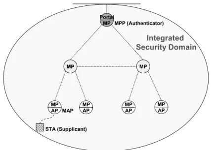
A security domain means a set of network entities on which a single security policy is employed by a single administrative authority [20]. As shown in Figure 1-1, a WLAN Mesh is composed of two security domains: mesh security domain (MSD) and AP secu-rity domain (ASD). A mesh portal (MPP) and mesh points (MPs) connecting to this MPP define an MSD; a pair of mesh access point (MAP) and STA defines an ASD. The security mechanism is different in the MSD and the ASD. Mesh links among MPs is protected by the 802.11s standard [14], but the connection between an STA and an MAP is protected by the 802.11i standard.
After an STA switched its serving MAP, the trustworthiness of the new MAP has to be ascertained by the STA, and vice versa. This is carried out by the reauthentication service. What is important at this stage is to determine the trustworthiness and establish a security association between each other.
Since EAP methods, e.g. PEAP and EAP-TTLS, are not optimized for reauthenti-cation, the overhead of 802.1X authentication certainly contributes to the handoff
la-tency. Previous researches for this issue only focus on the ASD. They neither integrate with the WLAN Mesh infrastructure nor deal with the routing overhead caused by secu-rity mechanisms in the multi-hop network.
MPP
MP MP
MAP MAP MAP MAP
AP Security Domain STA
Mesh Security Domain
Figure 1-1 WLAN Mesh security architecture
The routing performance in the multi-hop network suffers from the separated secu-rity architecture. As shown in Figure 1-2, due to the scope of pairwise transient key (PTK) is limited in a single hop, MPs on the routing path have to decrypt frames first and re-encrypt them with the next-hop PTK before forwarding. Such “hop-by-hop” processes not only incur overhead to MPs but also degrade the quality of real-time ser-vices seriously.
MPP
MP MP
MAP MAP MAP MAP
PTK3
PTK2
PTK1
STA
The objective of this research is to enhance the security mechanism of WLAN Mesh to improve the QoS for real-time services. It is achieved by reducing the handoff latency and eliminating the routing overhead caused by encryption processing. The proposed security mechanism should fulfill the following requirements:
1. Assure the security of 802.11i RSN.
2. Remove 802.1X authentication from handoff procedures.
3. Establish an end-to-end security channel between an STA and an MPP. 4. Avoid modifying STAs, including software and hardware.
5. Cooperate with the 802.11s standard.
1.3 Synopsis
The remainder of this thesis is organized as follows. Chapter 2 introduces background technologies and related works. Chapter 3 presents the proposed mechanism, including system architecture and message flows. The security analysis and the estimated handoff latency are presented in chapter 4 and chapter 5. At last, we conclude this research and introduce our future works in chapter 6.
Chapter 2
Background and Related Work
We begin this chapter by describing the system architecture and the security mechanism of WLAN Mesh, following by analyzing handoff procedures and latency. Finally, re-lated works are discussed.
2.1 WLAN Mesh Networking
The WLAN infrastructure usually consists of APs connecting to a wired network pro-viding wireless connectivity for STAs. The non-mesh WLAN deployment model is il-lustrated in Figure 2-1.
AP
STA
AP AP
Wired Network
Figure 2-1 Non-mesh WLAN infrastructure
An example of the WLAN Mesh infrastructure is shown in Figure 2-2. A WLAN Mesh is an 802.11-based wireless distribution system (WDS) consisting of a set of MPs interconnected via wireless links. An MP may be collocated with an AP to provide both mesh services and AP services in a single device referred to as MAP. STAs have to as-sociate with an MAP to access the WLAN Mesh.
Portal MP MP MP AP MP AP MAP MPP STA IEEE 802.11s IEEE 802.11i
Figure 2-2 WLAN Mesh infrastructure
MPs and MAPs participate in operations of the mesh networking, but STAs dose not. Two security mechanisms operate independently in the MSD and the ASD; hence the security architecture of WLAN Mesh is divided into two domains.
2.2 AP Security Domain
The security mechanism of ASD consists of 802.1X authentication, 4-way handshake and encryption protocols, i.e. TKIP and CCMP. The security mechanism is designed to establish a robust security network association (RSNA) between an STA and an MAP for securing the wireless connection.
Due to the delay of the ratification to 802.11i, Wi-Fi protected access (WPA), a subset of the 802.11i standard, is adopted by the Wi-Fi Alliance as a transitional solution to WEP insecurities. WPA2 is the full implementation of the 802.11i standard and pro-vides a robust security protocol for WLAN.
2.2.1
Architecture
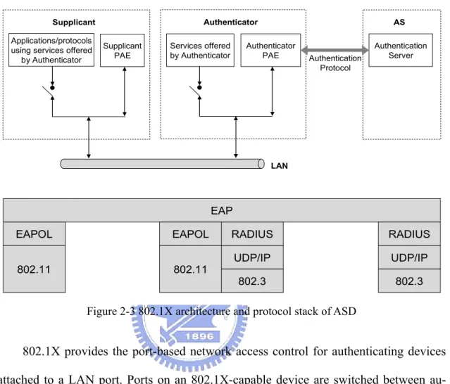
There are three components defined by 802.1X. As shown in Figure 2-3, the supplicant is an STA which requests to access WLAN Mesh. The authenticator is the serving MAP which controls the access to the network and blocks unauthorized traffics. The
authen-tication server (AS), e.g. a RADIUS server, provides authenauthen-tication services for check-ing the credentials of the supplicant on behalf of the authenticator.
Supplicant
Applications/protocols using services offered
by Authenticator
Supplicant PAE
Authenticator
Services offered
by Authenticator AuthenticatorPAE
LAN AS Authentication Server Authentication Protocol EAP EAPOL 802.11 EAPOL 802.11 RADIUS UDP/IP 802.3 RADIUS UDP/IP 802.3
Figure 2-3 802.1X architecture and protocol stack of ASD
802.1X provides the port-based network access control for authenticating devices attached to a LAN port. Ports on an 802.1X-capable device are switched between au-thorized state and unauau-thorized state. A port is enabled while in the auau-thorized state, or disable, while in the unauthorized state. The 802.1X specification permits initialization traffics, such as DHCP messages, to pass the port in the unauthorized state.
The protocol stack of 802.1X is illustrated in Figure 2-3. On the top is the EAP layer which includes the EAP protocol and EAP methods. The EAP protocol is a framework allows EAP methods to perform authentication transactions between the supplicant and the AS. EAP messages are carried by EAPOL frames transmitted be-tween the supplicant and the authenticator. All EAP messages are encapsulated into RADIUS packets and forwarded to the AS for further processing.
2.2.2
Authentication
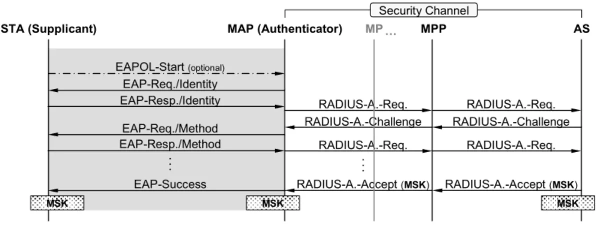
The message flows of 802.1X authentication are shown as Figure 2-4. Detail procedures are as follows:
STA (Supplicant) MAP (Authenticator) MPP AS
EAPOL-Start (optional) EAP-Req./Identity EAP-Resp./Identity Security Channel RADIUS-A.-Req. RADIUS-A.-Req. RADIUS-A.-Challenge RADIUS-A.-Challenge EAP-Req./Method
EAP-Resp./Method RADIUS-A.-Req. RADIUS-A.-Req.
. :
EAP-Success RADIUS-A.-Accept (MSK) RADIUS-A.-Accept (MSK) MP …
. :
MSK MSK MSK
Figure 2-4 802.1X authentication
1. An 802.1X authentication may be initialized by an EAPOL-Start message sent by the STA or an EAP-Request/Identity message sent by the MAP.
2. The STA responds the user identifier with an EAP-Response/Identity message, and the identifier is encapsulated into a RADIUS-Access-Request packet and forwarded to the AS.
3. The AS issues an authentication challenge. This challenge is passed to the STA as an EAP-Request/Method message for negotiating the EAP method used later.
4. The STA and the AS exchange the authentication information carried by EAP-Request/Respond messages. This step may be repeated many times de-pending on the EAP method.
5. After finishing the EAP authentication, both the STA and the AS generate a master session key (MSK). For authorizing the serving MAP, the MSK is dis-tributed from the AS to the MAP via the security channel.
EAP-Success message for indicating that the 802.1X authentication is com-plete.
2.2.3
Key Hierarchy
After an STA passed the 802.1X authentication, it is authorized to access the network, and the communication between the STA and its serving MAP should to be secured. In order to provide data encryption and integrity for the 802.11 connection, a key hierarchy is adopted by the 802.11i standard to derive a session key. Figure 2-5 illustrates the key hierarchy and derivations.
MSK or PSK PTK Authenticator PMK PTK Supplicant PMK PTK MSK PMK AS MSK MSK PSK
Figure 2-5 Key hierarchy and derivations of 802.11i
An MSK or a PSK is the highest order keys never exposed to any other party ex-cept the AS, the authenticator and the supplicant. The MSK is generated by the EAP method and consists of two portions: Enc-RECV-Key and Enc-SEND-Key. The suppli-cant and the authenticator may either take the Enc-RECV-Key or the PSK as a PMK. The PTK is a session key derived from the PMK, which collaborates with TKIP or CCMP to provide confidentiality, integrity and origin authenticity.
TKIP PTK (512 bits) KCK (128 bits) KEK (128 bits) TK (128 bits) MIC Key (128 bits) CCMP PTK (384 bits) KCK (128 bits) KEK (128 bits) TK (128 bits) PMK (256 bits)
Figure 2-6 PTK structure of TKIP and CCMP
802.11i defines two structures of PTK. As shown in Figure 2-6, both of TKIP and CCMP start with the EAPOL key confirmation key (KCK) used to compute the message integrity check of the EAPOL-Key message. After that is the EAPOL key encryption key (KEK) used to encrypt the EAPOL-Key message. The temporal key (TK), is used for data encryption. Since TKIP is designed to be compatible with the traditional en-cryption and authentication scheme of WEP, it requires an additional key to perform the Michael integrity check (MIC). For CCMP, the TK is used for both data encryption and integrity check.
2.2.4
RSNA Establishment
An STA has to first establish the RSNA with its serving MAP and is able to access WLAN Mesh. The procedures of RSNA establishment consist of 802.1X authentication and 4-way handshake. Figure 2-7 shows the message flows of RSNA establishment, where the MPP is not involved but forwards the authentication information to the AS.
STA (Supplicant) MAP (Authenticator) MPP AS Association Req. Association Resp. 802.11 802.1X EAPOL-Start (optional) EAP-Req./Identity EAP-Resp./Identity Security Channel EAP-Req./Method EAP-Resp./Method EAP-Success
EAPOL-Key(key-info, ANonce, PMKID) EAPOL-Key(key-info, ANonce, SNonce, MIC) EAPOL-Key(key-info, ANonce, SNonce, GTK, MIC)
EAPOL-Key(key-info, MIC)
MP … 4-way Handshake . : PMK PMK PTK PTK RADIUS-A.-Req. RADIUS-A.-Req. RADIUS-A.-Challenge RADIUS-A.-Challenge RADIUS-A.-Req. RADIUS-A.-Req. . : RADIUS-A.-Accept (MSK) RADIUS-A.-Accept (MSK)
Figure 2-7 802.11i RSNA establishment
1. After associating with the MAP, the STA performs 802.1X authentication. 2. The AS and the STA obtain an MSK from the EAP method. The AS
distrib-utes the MSK to the MAP.
3. The STA and the MAP derive a PMK from the MSK. If the PSK is used in-stead of the PMK, 802.1X authentication will be skipped.
4. The STA and the MAP perform 4-way handshake. To prevent replay attacks the MAP sends ANonce to the supplicant with message #1. The PMKID is also included in this message for synchronizing the PMK used in the hand-shake. Message #1 is neither encrypted nor authenticated, and thus the re-sponse missing or mismatching will fail the handshake.
5. The STA derives a fresh PTK and sends SNonce and robust security network information element (RSNIE) to the MAP with message #2. This message is authenticated whit the MIC calculated by the STA with the KCK.
6. The MAP derives the symmetric PTK and checks the integrity of message #2. If the MIC is invalid, the handshake fails, otherwise the MAP acknowledges
the STA that the PTK is successfully derived. In addition, a GTK could be also distributed to the STA with message #3.
7. The STA responds a confirmation to the MAP for informing that the PTK is installed. Message #4 is authenticated with the KCK, too.
8. After establishing the RSNA, the MAP switches the 802.1X port to the au-thorized state, and thus the network access is allowed.
2.3 Mesh Security Domain
The efficient mesh security association (EMSA) proposed by 802.11s secures mesh links between an MP and its peers, which includes EMSA authentication, 4-way hand-shake, key distribution and encryption protocols.
2.3.1
Architecture
The 802.1X architecture of MSD is essentially the same as ASD. However, since an MP is capable of utilizing and providing the distribution service, the roles of supplicant and authenticator are both adopted by the MP.
Figure 2-8 illustrates the 802.1X architecture of MSD. If MP A requires making use of the services provided by MP B, MP A’s supplicant PAE has to be authenticated by MP B’s authenticator PAE, and vice versa. Therefore, without the EMSA, an MP needs to perform enormous 802.1X authentications to establish the link security with peer MPs. For instance, an MP in the fully connected WLAN Mesh with 5 MPs and 10 mesh links will perform 8 rounds of 802.1X authentication.
LAN MP A Services offered by MP A Supplicant PAE Authenticator PAE AS Authentication Server MP B Services offered by MP B Supplicant PAE Authenticator PAE Authentication Protocol
Figure 2-8 802.1X architecture of the MSD
EMSA services permit two MPs efficiently establish the link security without per-forming 802.1X authentication. There are two types of mesh key holders defined by the EMSA: mesh authenticators (MAs) and mesh key distributors (MKDs). The functions of the 802.1X authenticator are distributed between MKD and MA. An MP may imple-ment one type or both.
2.3.2
Key Hierarchy
802.11s also introduces a new key hierarchy. As shown in Figure 2-9, an MSK or a PSK is the highest order key never exposed to any other party except the AS, the MKD and the supplicant MP. Under that the key hierarchy splits into two branches.
The left portion is the link security branch which provides keys for authentication and encryption between a supplicant MP and an MA. The functions of the PMK are di-vided into PMK-MKD and PMK-MA. The PMK-MKD is a proof that the supplicant has been authenticated. The PMK-MA is used to derive the session key and is generated by the MKD for each MA respectively. Separating the PMK functions is able to sim-plify following authentications for subsequent mesh link establishments.
PMK-MKD MSK or PSK PMK-MA (b) KDK PTK-KD PMK-MA (a) PTK (a) PTK (b) AS MKD PMK-MKD PMK-MAs KDKs PTK-KDs MA (a) MA (b) Supplicant PMK-MAs MSK PTKs PMK-MKD KDK (a) PTK-KD (a) PTK (a) PMK-MA (a)
PMK-MA (a) PMK-MA (b)
KDK (b) PTK-KD (b) PTK (b) PMK-MA (b) MSK MSK PSK
Figure 2-9 Key hierarchy and derivations of 802.11s
The right portion is the key distribution branch which provides keys to secure the distribution of PMK-MAs between an MKD and MAs. The KDK is a proof that the MA and the MKD have established the security association. The PTK-KD is the session key derived from the KDK to secure the PMK-MA distribution.
2.3.3
Initial EMSA Authentication
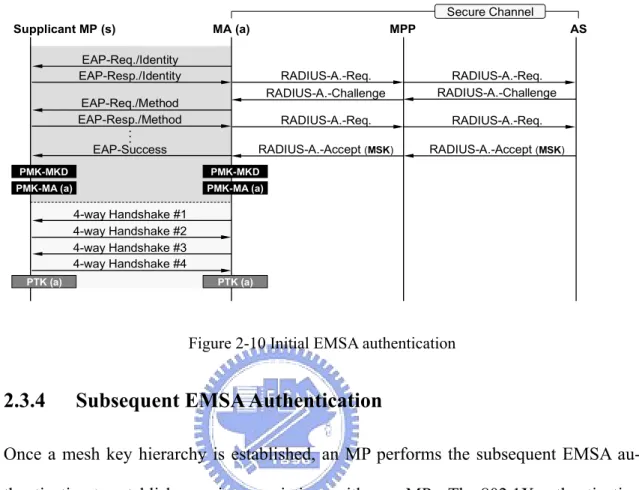
A supplicant MP which has not established any security association needs to perform the initial EMSA authentication to establish the EMSA with the MA. Moreover, a mesh key hierarchy is also constructed in both the supplicant MP and the MA. Figure 2-10 explains the initial EMSA authentication, where the MA (a) is an MKD.
1. The supplicant MP performs full 802.1X authentication with the MA (a). RADIUS messages are forwarded via the MPP.
2. The MSK is distributed from the AS to the MKD.
3. According to the mesh key hierarchy, the MKD and the supplicant MP derive the PMK-MKD and the PMK-MA (a)
PTK (a). Procedures of 4-way handshake are the same as the RSNA estab-lishment described in section 2.2.4.
Supplicant MP (s) MA (a) MPP AS EAP-Req./Identity EAP-Resp./Identity RADIUS-A.-Req. RADIUS-A.-Challenge EAP-Req./Method EAP-Resp./Method RADIUS-A.-Req. EAP-Success RADIUS-A.-Accept (MSK) 4-way Handshake #1 4-way Handshake #2 4-way Handshake #3 4-way Handshake #4 PMK-MKD Secure Channel . : PMK-MKD PMK-MA (a) PMK-MA (a) PTK (a) PTK (a) RADIUS-A.-Req. RADIUS-A.-Challenge RADIUS-A.-Req. RADIUS-A.-Accept (MSK)
Figure 2-10 Initial EMSA authentication
2.3.4
Subsequent EMSA Authentication
Once a mesh key hierarchy is established, an MP performs the subsequent EMSA au-thentication to establish security associations with peer MPs. The 802.1X auau-thentication is removed, and thus multiple mesh links can be established efficiently. The message flows of the subsequent EMSA authentication are shown as Figure 2-11.
1. The supplicant MP derives the PMK-MA (b) from the PMK-MKD generated in the initial EMSA authentication.
2. The MA (b) requests the PMK-MA (b) from the MKD, i.e. MA (a).
3. The MKD derives the PMK-MA (b) and encrypts it with the PTK-KD (b). After that, the PMK-MA (b) is distributed to the MA (b) with a PMK-MA De-livery Pull Mesh Action frame.
4. Once the supplicant MP and the MA (b) have the PMK-MA (b), they will perform 4-way handshake to derive the PTK (b).
Supplicant MP (s) MA (b) MKD AS 4 Way Handshake #1 4 Way Handshake #2 4 Way Handshake #3 4 Way Handshake #4 PMK-MKD Secure Channel KDK (b) PTK-KD (b) PMK-MA (b) PMK-MA (b) PMK-MA Request
PMK-MA Delivery Pull (PMK-MA)
PMK-MA (b)
PTK (b) PTK (b)
KDK (b) PTK-KD (b)
PMK-MKD
Figure 2-11 Subsequent EMSA authentication
The PTK-KD (b) is derived from the mesh key holder security handshake. Detail procedures of the handshake are described in the next section.
2.3.5
Mesh Key Holder Security Association
The mesh key holder security association provides data integrity and origin authenticity for the EAP authentication message transmitted between MA and MKD. Furthermore, it secures the distribution of PMK-MA and facilitates subsequent EMSA authentication.
After the supplicant MP passed the initial EMSA authentication, it can access the mesh network via the MA (a). However, if the supplicant MP further needs to operate as an MA, it has to establish the mesh key holder security association with the MKD. Figure 2-12 illustrates the message flows of the mesh key holder security handshake, where the MKD is the MA (a) mentioned in the previous section.
Supplicant MP (s) MKD MPP AS
Mesh Key Holder Security Handshake #1 PMK-MKD Secure Channel PMK-MKD KDK (s) KDK (s) PTK-KD (s) PTK-KD (s)
Mesh Key Holder Security Handshake #2
Mesh Key Holder Security Handshake #3
Figure 2-12 Mesh key holder security handshake
The mesh key holder security association start with the discovery of the MKD, followed by the 3-way handshake initiated by the MKD. After the handshake, a PTK-KD is derived from the KDK, and the supplicant MP (s) is able to provide the MA service. Frames transmitted between MA and MKD, such as the PMK-MA distribution, are encrypted by the PTK-KD.
2.3.6
EMSA Establishment
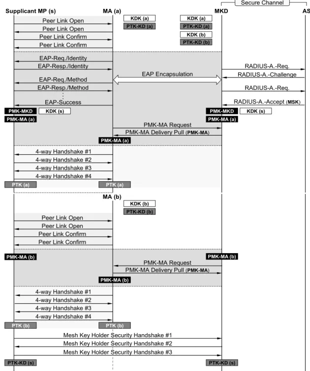
The overall message flows of the EMSA establishment and mesh key holder security association are shown in Figure 2-13, where the MKD and MAs are implemented at different MPs.
1. The supplicant MP establishes a mesh link with the MA (a) and performs full EAP authentication.
2. Since the MA (a) is not the MKD, all EAP messages are forwarded to the MKD with the mesh EAP message transport protocol. The MKD encapsulates EAP messages into RADIUS packets and forwards to the AS.
3. After the EAP authentication, the MKD constructs the mesh key hierarchy and distributes the PMK-MA (a) to the MA (a).
4. The MA (a) and the supplicant MP perform 4-way handshake to derive the PTK (a).
5. The supplicant MP continues to establish another mesh link with MP (b). The subsequent EMSA authentication is performed.
6. The supplicant MP establishes the mesh key holder security association with the MKD.
7. After all, two mesh links between are established, and the supplicant MP is ready to provide the MA service.
Supplicant MP (s) MA (a) MKD AS EAP-Req./Identity EAP-Resp./Identity RADIUS-A.-Req. RADIUS-A.-Challenge EAP-Req./Method EAP-Resp./Method RADIUS-A.-Req. EAP-Success RADIUS-A.-Accept (MSK) 4-way Handshake #1 4-way Handshake #2 4-way Handshake #3 4-way Handshake #4 PMK-MKD EAP Encapsulation Secure Channel . :
Peer Link Open Peer Link Open Peer Link Confirm Peer Link Confirm
KDK (a) PTK-KD (a) KDK (a) PTK-KD (a) PMK-MKD PMK-MA (a) PMK-MA (a) PMK-MA Request PMK-MA Delivery Pull (PMK-MA)
PMK-MA (a) KDK (s) KDK (s) PTK (a) PTK (a) KDK (b) PTK-KD (b) MA (b) 4-way Handshake #1 4-way Handshake #2 4-way Handshake #3 4-way Handshake #4
Peer Link Open Peer Link Open Peer Link Confirm Peer Link Confirm
KDK (b) PTK-KD (b)
PMK-MA (b) PMK-MA (b)
PMK-MA Request PMK-MA Delivery Pull (PMK-MA)
PMK-MA (b)
PTK (b)
Mesh Key Holder Security Handshake #1 Mesh Key Holder Security Handshake #2 Mesh Key Holder Security Handshake #3
PTK-KD (s) PTK-KD (s)
PTK (b)
2.4 IEEE 802.11 Handoff
Mobility is an inherent characteristic of the wireless networking. However, all wireless transmissions have a limited geographical range. The transmission range of an 802.11 AP is typically a few hundred feet. Upon moving out of the range of the current associ-ated AP, an STA enters into the range of another AP and performs handoff procedures to regain the connectivity.
Handoff mechanisms are designed to deal with STAs moving between APs, so that the continuous and QoS-guaranteed communication is supported. The 802.11 standard provides the mobility support for STAs traveling between basic service sets (BSSs), but not the extended service set (ESS).
Transitions between APs can be categorized into three types:
1. No transition. STAs move within the signal range of the current AP, no further considerations are needed.
2. BSS transition. STAs drop the connection to the current AP and then reassoci-ate with another AP in the same ESS. To reconnect to the distribution system (DS), STAs need to be authenticated by the new AP. Figure 2-14 gives an example of the BSS transition.
AP1
STA
ESS1, BSS1 ESS1, BSS2 ESS1, BSS3
AP2 AP3
Figure 2-14 BSS transition
3. ESS transition. STAs move from one AP to another AP in a distinct ESS. Higher-layer mobility management protocol, such as Mobile IP, is necessary
to support the seamless handoff. The ESS transition is out of scope of this re-search.
2.4.1
Handoff Latency
Handoff latency is the amount of time that the connectivity between an STA and the DS is lost. 802.11 handoff procedures consist of four portions: discovery phase, commit phase, authentication phase and handshake phase, where authentication phase and handshake phase are only introduced in the network applying 802.1X and 802.11i.
STA Target AP Association Req. Association Resp. EAPOL-Start (optional) EAP-Req./Identity EAP-Success 4-way Handshake #1 4-way Handshake #2 4-way Handshake #3 4-way Handshake #4 . :
Open System Authentication Req. Open System Authentication Resp.
Probe Req. Probe Resp. . : Discovery Phase Probe Req. Probe Resp. Commit Phase Authentication Phase Handshake Phase 20 ~ 300 ms 4 ~ 20 ms 750 ~ 1200 ms 10 ~ 80 ms
Figure 2-15 802.11 handoff procedures [5]
Because of signal strength decreasing or transmission errors, an STA decides to handoff to the target AP. In the discovery phase, the STA performs the active scan to construct a candidate AP list. The handoff algorithm chooses the “best” AP from the list to be the target AP and controls the STA to associate with it. Following that is the com-mit phase; the STA authenticates (open system) and associates with the target AP to es-tablish an 802.11 link. Current handoff latency in the non-802.11i environment is too
long to support real-time services1; nevertheless, the authentication phase makes it worse. The research [5] indicates that about 75% to 95% of the handoff latency is con-tributed by the 802.1X authentication.
802.1X authentication is composed of time-consuming mathematical operations. The EAP protocol needs several message round-trips to exchange the authentication in-formation and derivate keys. For example, the PEAP/EAP-MSCHAPv2 protocol re-quires 22 EAPOL messages. Moreover, authentication messages may be transmitted over the Internet while the AS resides in the remote network. Therefore, to support the seamless handoff, the substantial latency incurred by the 802.1X authentication must be eliminated.
2.5 Fast Authentication Methods
The issue of 802.1X authentication has been addressed. Some methods have been pro-posed to mitigate the overhead of 802.1X authentication and improve the handoff per-formance. Previous works are discussed in this section.
2.5.1
Preauthentication
With the preauthentication mechanism proposed by 802.11i, an STA is allowed to per-form 802.1X authentication with a new AP before associating with it. The preauthenti-cation separates the commit phase from the authentipreauthenti-cation phase and permits them to be performed independently.
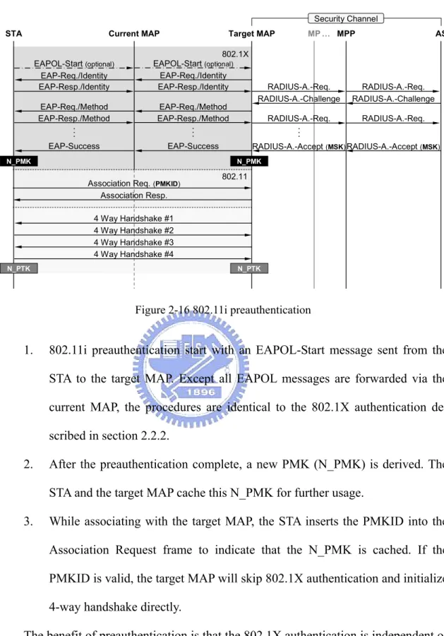
Because an STA can only associate with an AP at a time, preauthentication mes-sages transmitted between the STA and the target AP are forwarded via the current AP. Figure 2-16 shows the procedures of the 802.11i preauthentication.
RADIUS-A.-Accept (MSK) RADIUS-A.-Challenge
Current MAP Target MAP MPP AS
802.1X RADIUS-A.-Req. RADIUS-A.-Req. RADIUS-A.-Challenge RADIUS-A.-Req. RADIUS-A.-Req. RADIUS-A.-Accept (MSK) 4 Way Handshake #1 4 Way Handshake #2 4 Way Handshake #3 4 Way Handshake #4 MP … STA EAPOL-Start (optional) EAP-Req./Identity EAP-Resp./Identity EAP-Req./Method EAP-Resp./Method EAP-Success
Association Req. (PMKID) Association Resp. 802.11 . : . : Security Channel EAPOL-Start (optional) EAP-Req./Identity EAP-Resp./Identity EAP-Req./Method EAP-Resp./Method EAP-Success . : N_PMK N_PTK N_PTK N_PMK
Figure 2-16 802.11i preauthentication
1. 802.11i preauthentication start with an EAPOL-Start message sent from the STA to the target MAP. Except all EAPOL messages are forwarded via the current MAP, the procedures are identical to the 802.1X authentication de-scribed in section 2.2.2.
2. After the preauthentication complete, a new PMK (N_PMK) is derived. The STA and the target MAP cache this N_PMK for further usage.
3. While associating with the target MAP, the STA inserts the PMKID into the Association Request frame to indicate that the N_PMK is cached. If the PMKID is valid, the target MAP will skip 802.1X authentication and initialize 4-way handshake directly.
The benefit of preauthentication is that the 802.1X authentication is independent of the handoff procedures. An STA is able to authenticate with multiple candidate APs. However, preauthentication establishes authentication state and key management state on both the STA and candidate APs. To avoid the storage cost and the overhead of
pre-authentication burden AP and AS, STA should only preauthenticate with the AP that it is most likely to handoff to. Therefore, precisely target AP prediction is necessary for STA to perform preauthentication efficiently.
On the negative side, preauthentication is expensive in terms of computational power and latency for STA. The 802.1X authentication latency actually is not reduced by the preauthentication. To guarantee the QoS for real-time applications, an STA needs to perform preauthentication early enough before the current connection is dropped. Thus, well designed and overlapping coverage areas are essential to perform preauthen-tication successfully. In addition, preauthenpreauthen-tication introduces opportunities for DoS attacks. Malicious STAs could burden the AS by preauthenticating with a large number of APs.
2.5.2
PMK Sharing
PMK sharing mechanisms intend to reduce the authentication latency by distributing the PMK in use to candidate APs before the handoff. If the PMK is cached by the target AP, 802.1X authentication can be removed. PMK sharing mechanisms reduce not only the handoff latency, but also the overhead of AS and mesh network.
However, with PMK sharing mechanisms, a PMK is possible shared by all APs in the same ESS. Although the PMK mostly is encrypted during the distribution, the key transfer protocol still weakens the security of 802.11i RSN. A compromised PMK may affect all APs in the ESS. Moreover, sharing the PMK means that all APs in the ESS are capable of obtaining the content of the encrypted communication between an STA and its associated AP, which violates the 802.11i trust assumption2. On the other hand, modifications are needed for an STA to recalculate the PMKID of the shared PMK at different APs.
2.5.2.1 Needham-Schroeder Protocol
Jan et al. proposed a key distribution mechanism [15] adopting the Needham-Schroeder protocol to distribute a PMK among APs. Each AP and AS have a distinct symmetric key K, and thus AS can securely distribute the PMK to the AP.
Current MAP (c) Target MAP (t) MP … MPP AS STA
Association Req. (PMKID) Association Resp.
802.11 Target AP Auth. Req. (SSID) Target AP Auth. Resp. (SKs)
N_PTK N_PTK PMK K (c) K (t) SK Forwarding (SK) SK Forwarding ACK PMK Delivery(PMK) PMK SK SK SK PMK Delivery ACK PMK Distribution Success
PMK Distribution Req. (SSID) K (t)
K (c) SK SK PMK PMK Distribution Success 4 Way Handshake #1 4 Way Handshake #3 4 Way Handshake #4 4 Way Handshake #2
Figure 2-17 PMK sharing with the Needham-Schroeder protocol
Figure 2-17 illustrates the procedures of the PMK distribution. Details are as fol-lows:
1. The STA sends a request message to the current MAP. The SSID of the target MAP is included in this message.
2. The current MAP verifies the identity of the target MAP via the AS. If the target is legit, a session key SK is distributed to two MAPs. A security channel is constructed with the SK.
3. The PMK is transmitted from the current MAP to target MAP via the security channel.
distri-bution is complete.
5. After the PMK distribution, the target MAP skips 802.1X authentication and performs 4-way handshake with the STA.
2.5.2.2 Frequent Handoff Region Selection Algorithm
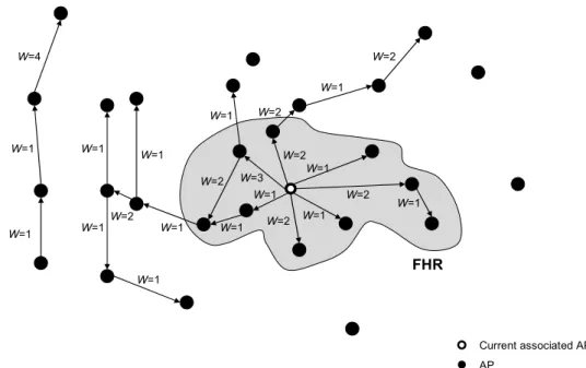
Pack et al. proposed a predictive handoff scheme referred to as frequent handoff region (FHR) scheme [19]. To reduce the authentication latency, an MSK is proactively dis-tributed to multiple APs depending on the STA’s mobility pattern. The FHR selection algorithm is also introduced to determine the subset of adjacent APs perhaps visited by the STA in the near future.
W=4 W=1 W=1 W=1 W=1 W=1 W=1 W=2 W=1 W=1 W=1 W=1 W=1 W=1 W=1 W=1 W=2 W=2 W=2 W=2 W=2 W=2 W=3 FHR Current associated AP AP
Figure 2-18 AP placement and FHR
Based on the historical handoff behaviors, a weighted directed graph of the AP placement shown in Figure 2-18 is constructed.
( )
( )
⎪ ⎪ ⎩ ⎪ ⎪ ⎨ ⎧ ∞ ≠ = = adjacent are not AP and AP , adjacent are AP and AP , , , 1 , 0 , i j j i H j i j i W j i j i (1)( )
( )
( )
j i R j i N j i Η , , , = (2) N(i, j) denotes the number of handoff events from the APi to the APj. R(i, j) denotesthe residential time in the APi before STAs handoff to the APj.
The number of APs selected into the FHR is limited by the weight value and the maximum hop count. Figure 2-18 gives an example of a FHR selected with the criterion that the weight value upper bound is 3 and the maximum hop count is 2.
Current MAP MAPs in the FHR MPP AS
4-way Handshake #1 4-way Handshake #2 4-way Handshake #3 4-way Handshake #4 MP … STA 802.11 Security Channel PTK 802.1X RADIUS-A.-Req. RADIUS-A.-Req. RADIUS-A.-Challenge RADIUS-A.-Req. RADIUS-A.-Req. RADIUS-A.-Accept (MSK) EAPOL-Start (optional) EAP-Req./Identity EAP-Resp./Identity EAP-Req./Method EAP-Resp./Method EAP-Success . : . : PMK Association Req. Association Resp. RADIUS-A.-Challenge RADIUS-A.-Accept (MSK) PTK PMK Encrypted Traffic 802.11 Association Req. Association Resp. 4-way Handshake #1 4-way Handshake #2 4-way Handshake #3 4-way Handshake #4 N_PTK N_PTK PMK *RADIUS-A.-Accept (MSK) Figure 2-19 FHR scheme
The authentication procedures of FHR scheme are shown in Figure 2-19, where the messages with the star symbol are different with 802.1X. The message flows of FHR scheme are the same as 802.11i, except the MSK is distributed to multiple MAPs. The AS proactively distributes the MSK to APs in the FHR, and thus the target AP can de-rive the PMK before the handoff.
The negative effect of FHR scheme includes not only the overhead of AS for maintaining FHR and monitoring the location of STAs, but also violating the key man-agement policy3 and the trust relationship of the EAP protocol.
2.5.3
PMK Predistribution
With PMK predistribution mechanisms, a new PMK is derived and distributed to can-didate APs in advance of the handoff. Due to a PMK can only be derived from an MSK obtained from the EAP method, a new key hierarchy has to be introduced to 802.11i. The key representing that an STA is authenticated and the key representing the permis-sion to access the network are separated. Some advanced MAC layer protocols, such as IEEE 802.16e, adopts this concept, too.
The key separation not only reduces the authentication overhead but also limits the impact of the compromised PMK in a single AP. PMK predistribution mechanisms do not introduce new security vulnerabilities beyond the 802.11i standard, except the weakness of the key distribution. However, new key hierarchies are not compatible with current wireless devices. In practice, to update or replace all devices will be an arduous problem.
2.5.3.1 Neighbor Graph Algorithm
A proactive key distribution scheme [16] proposed by Mishra et al. introduces a
sive PMK derivation function, where
(
MSK,PMK |AP_MAC|STA_MAC)
PRFTLS
PMKn = − n-1 (3)
The PMK0 is generated by the original key derivation function of 802.11i. A dis-tinct PMKn is distributed from AS to each adjacent APs of the associated AP
respec-tively before the handoff, and thus the authentication phase are estimated.
To distribute PMK efficiently, AS maintains a data structure named neighbor graph (NG) to determine the set of candidate APs. The neighbor graph integrates the geo-graphic information and is able to provide the accurate list of APs that an STA could potentially reassociate with.
A E D B C A E D B C
Figure 2-20 AP placement and the corresponding neighbor graph
An example of the AP placement is shown in Figure 2-20. The dotted line repre-sents a potential path for the movement of STAs. If two APs are connected by a dotted line, there will be an edge between the APi and the APj in the neighbor graph, which is
represented the handoff relationship.
PMK0 PMKB PMKE PMKA PMKE PMKC PMKE
Take an STA moving from A to C via B for example, the PMK derivations are shown as Figure 2-21. Note that if an AP appears in the candidate set repeatedly, the key duplication problem will happen, e.g. PMKE. This will result in the extra storage cost and the synchronization problem.
Current MAP Adjacent MAPs MPP AS
4-way Handshake #1 4-way Handshake #2 4-way Handshake #3 4-way Handshake #4 MP … STA 802.11 Security Channel PTK0 802.1X RADIUS-A.-Req. RADIUS-A.-Req. RADIUS-A.-Challenge RADIUS-A.-Req. RADIUS-A.-Req. EAPOL-Start (optional) EAP-Req./Identity EAP-Resp./Identity EAP-Req./Method EAP-Resp./Method EAP-Success . : . : PMK0 Association Req. Association Resp. RADIUS-A.-Challenge RADIUS-A.-Accept (MSK) PTK0 *Notify-Req. 802.11 Association Req. Association Resp. 4-way Handshake #1 4-way Handshake #2 4-way Handshake #3 4-way Handshake #4 PTKn Encrypted Traffic PTKn *Notify-Accept *Access-Accept (PMK) PMKn PMK0 PMKn *Notify-Req. *Notify-Accept *Access-Accept (PMK) RADIUS-A.-Accept (MSK)
Figure 2-22 Neighbor graph algorithm
Figure 2-22 illustrates the message flows of NG scheme. If an STA passed the ini-tial 802.1X authentication, the AS will send a Notify-Request message to the adjacent MAPs of the current MAPs to inform that the STA may handoff to. The adjacent MAPs either reply a Notify-Accept message to request the PMKn or a Notify-Reject message
to bypass the PMK predistribution.
The disadvantage of NG scheme is the burden of AS for tracking the location of STAs and requiring multiple PMK derivations and distributions for each handoff.
2.5.3.2 Fast BSS Transition
802.11r [13] proposed a mechanism to minimize the handoff latency during the BSS transition. The fast BSS transition mechanism permits an STA to establish link security with the target AP prior to or during the commit phase, and thus avoids the delay in connecting to the DS after the handoff. The security improvements of 802.11r include:
1. Define a set of APs named mobility domain (MD). Once an STA passed the 802.1X authentication in any AP within the MD, the subsequent authentica-tions can be skipped while the STA reassociates with other APs within the same MD.
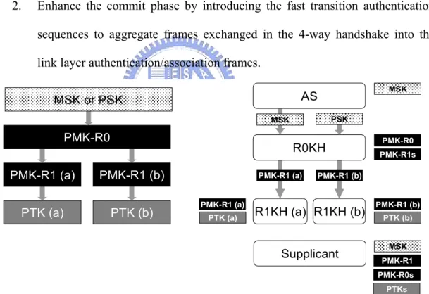
2. Enhance the commit phase by introducing the fast transition authentication sequences to aggregate frames exchanged in the 4-way handshake into the link layer authentication/association frames.
PMK-R0 MSK or PSK PMK-R1 (b) PMK-R1 (a) PTK (a) PTK (b) AS R0KH PMK-R1sPMK-R0 R1KH (a) R1KH (b) Supplicant PMK-R0s MSK PTKs PMK-R1 PTK (a) PMK-R1 (a) PMK-R1 (a) PMK-R1 (b) PTK (b) PMK-R1 (b) MSK MSK PSK
Figure 2-23 Key hierarchy and derivations of 802.11r
As shown in Figure 2-23, a new key hierarchy and two types of the key holder are introduced by 802.11r. The functions of 802.1X authenticator are distributed among a PMK-R0 key holder (R0KH) and PMK-R1 key holders (R1KHs). The R0KH derives a PMK-R1 from the PMK-R0 for each PMK-R1 key holder (R1KH) within the MD. The
R1KH derives the PTK mutually with the STA through the 4-way handshake.
As shown in Figure 2-24, the STA performs the initial fast transition (FT) associa-tion while first entering the MD. After that, the R0KH, i.e. the current MAP, predistrib-utes the PMK-R1 to the target MAP. The distribution protocol is not defined by 802.11r, but some implementations choose the IAPP CACHE-notify mechanism to distribute PMK-R1.
Current MAP (R0KH) Target MAP (R1KH) MPP AS
4-way Handshake #1 4-way Handshake #2 4-way Handshake #3 4-way Handshake #4 MP … STA 802.11 Security Channel 802.1X RADIUS-A.-Req. RADIUS-A.-Req. RADIUS-A.-Challenge RADIUS-A.-Req. RADIUS-A.-Req. EAPOL-Start (optional) EAP-Req./Identity EAP-Resp./Identity EAP-Req./Method EAP-Resp./Method EAP-Success . : . : Association Req. Association Resp. RADIUS-A.-Challenge RADIUS-A.-Accept (MSK) PMK-R0 PMK-R1 (a) PMK-R0 PMK-R1 (a) RADIUS-A.-Accept (MSK) PMK-R1 (b) *PMK Delivery (PMK-R1) PTK (a) PTK (a) PMK-R1 (b)
Figure 2-24 802.11r initial FT association and PMK-R1 predistribution
802.11r defines two mechanisms to improve the handoff performance. The authen-tication information exchanged between STA and target AP is either directly transmitted over the air in the commit phase (referred to as the Over-the-Air) or forwarded via the current AP before the handoff (referred to as the Over-the-DS).
The procedures of Over-the-Air fast BSS transition are shown in Figure 2-25. The FT authentication allows a fresh PTK to be computed in the commit phased, and thus authentication phase and handshake phase of are removed.
STA Target MAP
PMK-R1(b) PMK-R1(b)
PTK (b) PTK (b)
Authentication Req. (FT, MDIE, FTIE[SNonce, R0KH-ID]) Authentication Resp. (FT, MDIE, FTIE[ANonce, SNonce])
Association Req. (MDIE, FTIE[ANonce, SNonce, MIC]) Association Resp. (MDIE, FTIE[ANonce, SNonce, GTK, MIC])
Over-the-Air FT
Current MAP
Figure 2-25 Over-the-Air FT authentication
The procedures of Over-the-Ds fast BSS transition are shown in Figure 2-26. FT Action frames carried the authentication information are forwarded between the STA and the target MAP via the current MAP. The MAC address of the target MAP is speci-fied in the FT Action Request frame to indicate the forwarding destination.
STA
PMK-R1(b)
PTK (b)
FT Action Req. (STA, TargetAP, FTIE[SNonce, R0KH-ID]) FT Action Resp. (STA, TargetAP, FTIE[ANonce, SNonce])
Association Req. (MDIE, FTIE[ANonce, SNonce, MIC]) Association Resp. (MDIE, FTIE[ANonce, SNonce, GTK, MIC])
Target MAP PMK-R1(b) PTK (b) Over-the-DS FT Current MAP FT Action Req. FT Action Resp.
Figure 2-26 Over-the-DS FT authentication
The Over-the-DS mechanism minimizes the message exchanges for an STA to re-gain the connectivity, and thus the handoff latency can be significantly reduced.
However, fast BSS transition mechanism needs to determine the candidate APs for the PMK-R1 predistribution. If the prediction is missing, target MAP will have to re-trieve the PMK-R1 from R0KH after the handoff, and it will cause extra latency. More-over, the message aggregation for 4-way handshake will certainly increase the latency of the original commit phase.
2.5.4
Summary
The design of 802.11i, such as key hierarchy and redundant open system authentication, does not take the handoff into consideration and affects the quality of time-sensitive ap-plications. Furthermore, most EAP methods require multiple round-trip message ex-changes and will result in significant authentication latency.
Since 802.11 is a link layer protocol, it should not touch the problem out of the scope, i.e. EAP authentication latency. Related researches focus on reducing the demand of the EAP authentication instead of improving it.
802.11r provides a solution to optimize message exchanges and separate the 802.1X authentication from the network access control. However, considerable quanti-ties of conventional WLANs have been deployed. These devices support neither the fast authentication nor the target AP prediction. It is impossible to replace or update all de-vices in the near future.
Besides, the 802.11 handoff is a mobile controlled handoff (MCHO), while the handoff decision is decided by the STA. Since STAs are powered by the battery, the handoff algorithms must consider the power consumption of the signal measuring and analysis. Some mechanisms, such as the NG scheme, can provide the precisely target AP prediction but require the topology information to assist the decision.
We propose a new security mechanism for STAs to remove the authentication phase from handoff procedures. The proposed mechanism performs on the premise that the security of 802.11i RSN is assured. Neither MSK nor PMK is transmitted via the wireless media. Furthermore, no modifications are needed for STAs to apply the new mechanism. The proposed mechanism is presented in the next chapter.
Chapter 3
Integrated Security Domain
To reduce the overhead of authentication and encryption processing, we propose a mechanism to integrate the security domains of WLAN Mesh. An MPP and the MAPs connected to this MPP form an integrated security domain (ISD). An STA only performs 802.1X authentication while first time connects to an MAP within the ISD. Authentica-tion latency is removed from the following handoffs in the same ISD. Furthermore, an end-to-end security channel between an STA and an MPP is established without ex-changing any extra message. The security channel can improve the performance of WLAN Mesh in routing the encrypted frame.
3.1 Architecture
With ISD, security functions of the AP services, such as 802.1X authentication and RSNA key management, are implemented in the MPP. As shown in Figure 3-1, the role of 802.1X authenticator is adopted by the MPP instead of the serving MAP.
STA (Supplicant) Integrated Security Domain Portal MP MP MP MP AP MP AP MP AP MP AP MPP (Authenticator) MAP
MAP is the edge of WLAN Mesh and responsible for blocking malicious STAs from accessing the network. In order to provide the ability for MAP to verify frame in-tegrity, PTK and GTK are distributed from MPP to the serving MAP via secured mesh links right after 4-way handshake. Figure 3-2 shows the PTK distribution.
MPP
MP
MAP MAP MAP
MP MAP PTK PMK PTK PMK PTK STA Figure 3-2 PTK distribution
3.2 RSNA Establishment
While an STA initially associated to any MAP within the IDS, it is required to perform 802.1X authentication and 4-way handshake to establish the security association with the MPP. For being compatible with conventional STAs, the message flows in the STA portion are identical to ISD and 802.11i in the RSNA establishment.
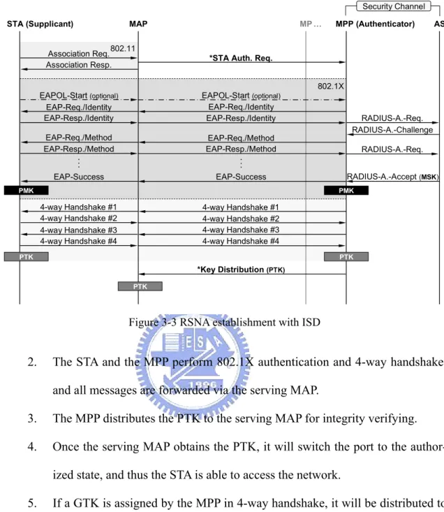
Since MPP is an authenticator, serving MAP participates in neither 802.1X authen-tication nor 4-way handshake but forwards all authenauthen-tication messages between STA and MPP. Figure 3-3 illustrates the procedures of RSNA establishment for an STA ini-tially authenticating with an MAP within the ISD.
1. The serving MAP checks the Association Request frame to see is any PMKID included. If not, an STA Authentication Request message is sent to the MPP to initialize 802.1X authentication.
RADIUS-A.-Req. RADIUS-A.-Challenge RADIUS-A.-Req. RADIUS-A.-Accept (MSK) MAP MP … MPP (Authenticator) AS STA (Supplicant) 802.11 Security Channel EAPOL-Start (optional) EAP-Req./Identity EAP-Resp./Identity EAP-Req./Method EAP-Resp./Method EAP-Success . : Association Req. Association Resp. PMK PTK 802.1X EAPOL-Start (optional) EAP-Req./Identity EAP-Resp./Identity EAP-Req./Method EAP-Resp./Method EAP-Success . : PMK *Key Distribution (PTK) *STA Auth. Req.
4-way Handshake #1 4-way Handshake #2 4-way Handshake #1 4-way Handshake #2 4-way Handshake #3 4-way Handshake #4 4-way Handshake #3 4-way Handshake #4 PTK PTK
Figure 3-3 RSNA establishment with ISD
2. The STA and the MPP perform 802.1X authentication and 4-way handshake, and all messages are forwarded via the serving MAP.
3. The MPP distributes the PTK to the serving MAP for integrity verifying. 4. Once the serving MAP obtains the PTK, it will switch the port to the
author-ized state, and thus the STA is able to access the network.
5. If a GTK is assigned by the MPP in 4-way handshake, it will be distributed to the serving MAP as well.
3.3 Handoff Procedures
802.11s allows multiple MPPs reside in one WLAN Mesh, and thus the handoff behav-iors with ISD are categorized into intra-MPP handoff and inter-MPP handoff. Moreover, the authentication procedures vary in the two types.
3.3.1
Intra-MPP Handoff
Intra-MPP handoff means that an STA drops current connection and reassociates with another MAP connecting to the same MPP.
MP AP1
STA
ESS1, BSS1 ESS1, BSS2 ESS1, BSS3
MPP
MP
AP2 AP3MP
Figure 3-4 Intra-MPP handoff
Since MPP is the authenticator, STA does not change the authenticator in the in-tra-MPP handoff. If the PMK is cached by the authenticator, 802.1X authentication will be skipped. Figure 3-5 illustrates the message flows of intra-MPP handoff.
Current MAP MP … MPP (Authenticator) AS STA (Supplicant)
802.11
EAPOL-Start (optional) EAP-Success (optional) Association Req. (PMKID)
Association Resp. PMK N_PTK PMK *Key Distribution (PTK) 4-way Handshake #1 4-way Handshake #2 4-way Handshake #3 4-way Handshake #4 PTK Target MAP 802.1X 4-way Handshake #4 *PMK Veri. (PMKID) *PMK Veri. Success 4-way Handshake #1 4-way Handshake #2 4-way Handshake #3 N_PTK
Figure 3-5 Intra-MPP handoff with ISD
1. The STA reassociates with the target MAP. The PMKID is passed to the MPP for verifying the PMK cached in the STA.
valid, the MPP will inform the target MAP with a PMK Verification Success message.
3. Some implementations4 of the supplicant use the EAPOL-Start message to initialize 802.1X authentication. If the target MAP receives an EAPOL-Start message, it will reply an EAP-Success message to skip the EAP authentica-tion.
4. Following 4-way handshake and PTK distribution are identical to the RSNA establishment mentioned before.
3.3.2
Inter-MPP Handoff
Inter-MPP handoff is performed while an STA moves from one MAP to another MAP connecting to the different MPP. The STA will switch to another ISD in the inter-MPP handoff.
MP AP1
STA
ESS1, BSS1 ESS1, BSS2 ESS1, BSS3
MPP1
MP
AP2 AP3MP
MPP2
Figure 3-6 Inter-MPP handoff
If the ISD has not been visited by the STA or the cached PMK is expired, preau-thentication will be performed. However, the STA may fail to preauthenticate with the new MPP, and thus the overhead of 802.1X authentication is introduced.
There are many factors cause preauthentication to be failed, such as the moving speed of the STA, the size of the overlapping coverage area, the target AP prediction,
4The EAPOL-Start message is used by Wireless Zero Configuration service in Windows XP, but not
the latency of EAP authentication, etc.
RADIUS-A.-Req. RADIUS-A.-Challenge
RADIUS-A.-Req.
RADIUS-A.-Accept (MSK)
Target MAP MP … MPP (Authenticator) AS STA (Supplicant) 802.11 Security Channel N_PMK N_PTK 802.1X EAPOL-Start (optional) EAP-Req./Identity EAP-Resp./Identity EAP-Req./Method EAP-Resp./Method EAP-Success . : N_PMK *Key Distribution (PTK) *PMK Veri. Req. (PMKID)
4-way Handshake #1 4-way Handshake #2 4-way Handshake #3 4-way Handshake #4 N_PTK N_PTK Current MAP EAPOL-Start (optional) EAP-Req./Identity EAP-Resp./Identity EAP-Req./Method EAP-Resp./Method EAP-Success . :
Association Req. (PMKID) Association Resp. 4-way Handshake #1 4-way Handshake #2 4-way Handshake #3 4-way Handshake #4 *PMK Veri. Failed PMK
Figure 3-7 Inter-MPP handoff with ISD
Figure 3-7 illustrates the message flows of inter-MPP handoff and RSNA estab-lishment. Detail procedures are as follows:
1. The STA reassociates with the target MAP. The PMKID is forwarded to the MPP for verifying the PMK cached in the STA.
2. Since the new MPP does not cache the PMK, the PMKID verification is failed, and a message will be sent to the target MAP for informing that following au-thentication messages should be forwarded to the MPP.
3. 802.1X authentication and 4-way handshake are performed, followed by the PTK distribution. The procedures are the same as the RSNA establishment described in section 3.2.
![Figure 2-15 802.11 handoff procedures [5]](https://thumb-ap.123doks.com/thumbv2/9libinfo/8497527.185028/33.892.250.733.422.857/figure-handoff-procedures.webp)