i
國
立
交
通
大
學
資訊科學與工程研究所
碩
士
論
文
於 I P - b a s e d 網 路 利 用 識 別 碼 進 行
封 包 標 記 與 路 徑 回 溯 追 蹤 之 研 究 與 實 作
Study and Implementation of Identification-based
Packet Marking and Route Traceback in IP-based Networks
研 究 生:黃民翰
指導教授:趙禧綠 教授
ii
於 IP-based 網路利用識別碼進行
封包標記與路徑回溯追蹤之研究與實作
Study and Implementation of Identification-based Packet Marking
and Route Traceback in IP-based Networks
研 究 生:黃民翰 Student:Tim Hann Huang
指導教授:趙禧綠 Advisor:Hsi-Lu Chao
國 立 交 通 大 學
資 訊 科 學 與 工 程 研 究 所
碩 士 論 文
A Thesis
Submitted to Institute of Computer Science and Engineering College of Computer Science
National Chiao Tung University in partial Fulfillment of the Requirements
for the Degree of Master
in
Computer Science
July 2009
Hsinchu, Taiwan, Republic of China
iii
於 IP-based 網路利用識別碼進行封包標記與路徑回溯追蹤之研究與實作
學生:黃民翰
指導教授:趙禧綠
國立交通大學資訊科學與工程研究所碩士班
摘 要
隨著網路技術的發展,網路安全的議題逐漸受到重視。許多攻擊者在網路上使用僞 裝的來源位址進行封包傳遞,隱藏自己的位置,以致現今路徑回溯追蹤方法,無法找到 正確的攻擊來源位址。現今路徑回溯追蹤的方法是利用所收到的封包,取得封包內的來 源位址,向來源位址發送封包,所經過的路由器會回傳本身位址資訊,達到路徑回溯追 蹤。當來源位址是偽造時,往回發送的封包,傳送的路徑並非攻擊封包使用的傳送路徑, 因此追蹤出錯誤的路徑。封包標記是路徑回溯中重要的一環,在封包的傳遞過程中,經 過擁有封包標記的主機,受害者收集這些標記的內容,去追蹤出正確的路徑。本篇論文 提出一個簡單的封包標記與標記記錄追蹤的方法,在僞裝來源位址的情況下,依然能夠 正確追蹤出傳送的來源,對於即時性與非即時性的追蹤都可達成。這個方法需要使用到 IP Option 的欄位,標記方式是將設定的識別碼加入 IP Option 的欄位,並將經過的每一 個標記主機記錄下來,最後再使用這些標記資訊,進行路徑的查詢,以找出攻擊者的位 置,達到路徑追蹤的效果。 關鍵詞: 網路安全、偽造網路位址、封包標記、路徑回溯追蹤iv
Study and Implementation of Identification-based Packet Marking
and Route Traceback in IP-based Networks
Student: Tim Hann Huang
Advisor:Hsi-Lu Chao
Institute of Computer Science and Engineering
National Chiao Tung University
Abstract
Along with the development of Internet, network security becomes important. Many attackers spoofed the source address of the packets in the internet. The method of traceback would not trace the true path of source which is spoofed. The method of traceback used the source address of the packet and sent the packet to the source address. The router along the path will return the IP address of itself. The victim can used these messages to rebuild the path. But the source address is spoofed so that the trace path is wrong. According to this reason, packet marking used to get the accurate trace path. The packets across the marking machine were marked by marking procedure. The victim could collect or gather the marking information to trace the accurate paths. This paper describes a simple method of packet marking for IP traceback. The packets with spoofing address could be traced the accurate paths by marking information. The Identification-based Packet Marking (IPM) for Real-Time/Non-Real-Time is effective to trace route. The IPM marks identifiers to the IP Option field and los the marking information. Afterwards, we could find the path of packet’s transmission by analyzing the marking information.
v
致 謝
在碩士一路下來,從環境的未知開始熟習,在修習課程結交了許多朋友,共同的努 力完成課業上的課題,作業的討論,團隊的合作,從中獲得許多能力,感謝朋友們的幫 忙與協助。 在自己的計劃當中,遇到最困難的就是從未碰過的東西,第一次開始接觸 Linux 的 時候,就必須朝向最困難的 Kernel 開始修改,新手的自己總是遇到重重困難,藉著網路 的搜尋,書籍的借閱以及向相關研究的同學詢問,達成所需要的實作內容,特別感謝同 樣研究的同學耐心的教導與回答。 核心編程,算是這全部份最重要也最困難的地方,有了老師指導實作的方向,修改 內容符合實際要求,然而常常遇到瓶頸無法解決,花了很多時間在研究程式編寫,然而 老師的說法讓我有許多新的想法與思考,從中獲得許多不同的看法,感謝老師在這方面 的指示與教導。 在碩士後來的過程中,非常感謝學弟妹的幫助,讓我減輕不少的壓力,能夠順利的 準備畢業前夕的資料,也完善的達成最後的目標,變成現在的成果,感謝學弟妹的精力 與體力的提供。 最後感謝父母的關心與鼓勵,家庭與外宿有很長一段距離,經常在電話詢問最近的 狀況,擔心我身體沒照顧好,或是吃得不夠多,常常寄水果與零食給我,讓我能夠安穩 的在這學習與完成自己的學業,謝謝父母們的照顧。 黃民翰 2009 年 7 月 6 日于新竹交通大學vi
Contents
摘 要 ... iii Abstract ... iv 致 謝 ... v Contents ... viList of Tables ... viii
Lists of Figures ... ix
Chapter 1. Introduction ... 1
1.1. Traceback Approaches ... 2
1.2. Contribution ... 3
1.3. Organization ... 3
Chapter 2. Related Work ... 5
2.1. Probabilistic Packet Marking Scheme ... 5
2.2. Deterministic Packet Marking Scheme ... 7
2.3. Router Interface Marking Scheme ... 9
2.4. Logging Scheme ... 9
Chapter 3. Packet Marking and Route Traceback ... 10
3.1. Design Conception ... 10
3.2. The Proposed Packet Marking Module ... 11
3.3. The Proposed Logging Module ... 14
3.4. The Proposed Traceback Module ... 15
3.5. System Architecture ... 17
3.6. Algorithm Design ... 18
3.6.1. The Process of Packet Marking ... 19
3.6.2. The Process of Packet Logging ... 20
3.6.3. The Process of Traceback ... 21
Chapter 4. Performance Evaluation ... 23
4.1. Attack Scenario ... 23 4.2. Experiment Environment ... 23 4.2.1. Hardware ... 23 4.2.2. Network Topology ... 24 4.2.3. Functions ... 25 4.3. Experiment Scenarios ... 26 4.4. Experiment Result ... 27 4.4.1. Setting Result ... 28 4.4.2. Sniffer Result ... 30
vii
4.4.3. Database Result ... 31
4.4.4. Traceback Result ... 32
Chapter 5. Conclusion and Future Work ... 35
References ... 37
Appendix A. Codes ... 38
viii
List of Tables
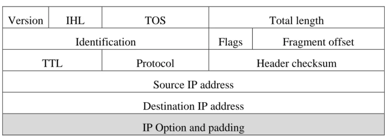
Table 1 Fields of IP header ... 12
Table 2 Design of our IP option ... 12
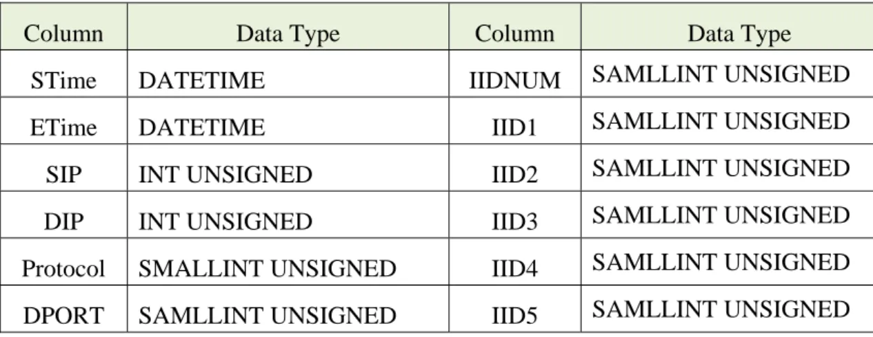
Table 3 Columns and data type in the table... 14
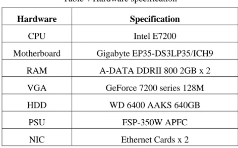
Table 4 Hardware specification ... 24
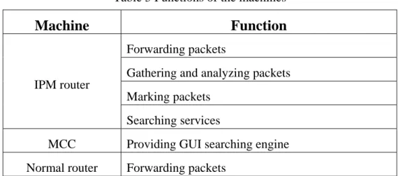
Table 5 Functions of the machines ... 26
ix
Lists of Figures
Figure 1 Network as seen from a victim of an attack ... 5
Figure 2 Encoding edge fragment into the IP identification field ... 7
Figure 3 DPM only works in the router R1 ... 8
Figure 4 Network architecture ... 10
Figure 5 Three modules of IPM router ... 11
Figure 6 Process of traceback scheme ... 16
Figure 7 Example of the traceback scheme ... 17
Figure 8 Overview of System architecture of IPM router ... 17
Figure 9 Components between IPM Router and MCC ... 18
Figure 10 Procedure of Bridge model ... 19
Figure 11 Algorithm of packet marking process ... 19
Figure 12 Procedure of packet transmission through sniffer ... 20
Figure 13 Algorithm of packet logging ... 21
Figure 14 Connection between MCC and IPM router ... 22
Figure 15 Scenario of packet spoofing from an attack ... 23
Figure 16 Network topology ... 25
Figure 17 Traceroute process by victim ... 27
Figure 18 Traceback process by IPM router ... 28
Figure 19 Commands of the IPM router ... 29
Figure 20 Operations of the IPM router ... 29
Figure 21 Domain control and file loading ... 30
Figure 22 Packet information gathered from the sniffer ... 31
Figure 23 Records in the database ... 32
Figure 24 Traceback with the condition “Source IP and Port” ... 33
Figure 25 Traceback with the condition “Destination IP and Date” ... 33
Figure 26 Traceback with the condition “Date and Time” ... 34
Figure 27 Association ... 38
Figure 28 Installation of packets from Internet ... 75
Figure 29 The table “tam” in the database “wnl” ... 76
Figure 30 Commands for bridge setup ... 77
Figure 31 The setting of network rules ... 77
Figure 32 Sniffer for each interface ... 78
- 1-
Chapter 1.
Introduction
Internet security has been an important research in the recent years. Traceback is one of
interesting problems to exhibit the route and pinpoint the true source of received packets. The
origins of the problems are the stateless nature of the Internet, the destination-oriented routing
and the lack of verification of the source IP address. The attackers utilize these facts to
conceal their identities by forging the source address of their attack packets, which is
generally known by IP spoofing. IP spoofing technique makes the attackers difficult to detect
and trace.
Denial of Service (DoS) and Distributed Denial of Service (DDoS) attacks are the threats
to the Internet Infrastructure. An Attacker dominates several hosts, called agents, to inundate
a large number of packets to the same host, called victim. The enormous volume of traffic
aggregates at the victim so that the congestion and packet loss are occurred. Additionally,
Resources of the victim are consumed by the traffic of attacks. Hence, The Resources are
unavailable for legitimate clients. The quality of the victim is growing worse and being
destroyed. DoS and DDoS are the most common to take advantage of IP spoofing. There are
two purposes of IP spoofing. One of the purposes is to conceal the identities of attackers so
that the victim fails to trace back to the sources of attacks. The other is to make difficult to
distinguish the spoofed packets from valid packets. The victims can not verify whether the
source address carried by the packet is valid or not. Therefore, it is motive for attackers to
force the source IP address.
As already mentioned, IP spoofing is a serious problem. The solution of IP traceback is
the major goal. Traceback mechanisms have been proposed to trace the real source of the
attackers. The one of the purposes is to cease the attacks at the position nearest to its source in
order to reduce waste of network resources. The other is to find the identity of the attackers in
order to take other legitimate actions against them. In backtracking techniques, the traceback
- 2-
elements of the victim are transmitted a description of the flow. They are requested to identify
if a same flow is routed locally; this supposes that the routed flow is successful to the
backtracking mechanism. If so, neighbors should be identified in order to repeat the operation.
This operation is performed recursively until identities of attacks are discovered.
1.1.
Traceback Approaches
The existing approaches for IP traceback could be grouped into two dimensions: packet
marking and packet logging. The main idea behind packet marking is to record path
information in packets. Routers write their own identification information into header fields of
forwarded packets in mark-based traceback. The victim then retrieves the marking
information from received packets and determines the routing path by the collection of
marked packets. Due to the limited spaces of the marking fields, routers probabilistically
decide to mark packets. Therefore, each marked packet only carries partial information of the
path. The path can be constructed by combining the marking information collected from a
number of received packets. Such approach is known as probabilistic packet marking (PPM)
[1]. PPM incurs little overhead of the packets at routers. However, it requires some of marked
packets to construct the path from victim to their origin.
The main idea in packet logging is to record path information at routers. Packets are
logged by the routers on the path toward the destination in log-based IP traceback. The path is
constructed based on the information of logs at the routers. The log-based approach is more
powerful as it can trace attacks that use a single packet. However, it is impractical due to that
the enormous resources for packet logs. A hybrid IP traceback approach based on both packet
marking and packet logging maintains single packet traceback and alleviates the resources for
packet logs. Such approach is the main goal for us to trace the position nearest to the attacks.
Combining two approaches is closed related to the techniques of packet marking and
packet logging. Many researchers proposed packet marking approaches for constructing the
path toward to the sources of attacks. Majority of them utilizes the fields used unusually in the
- 3-
not increase the traffic load of the internet and does not change the measure of packet
proposition. However, it induces errors occurred in the fragmentation and reassembly of IP
datagram and is limited marking fields to a small amount of spaces. Others are appends IP
Option fields into the packet of IP header in order to attach the marking information to the
packets. Compared to the preceding method, the marking fields are possessed of large spaces
for appending marking information. Nevertheless, the method raises the traffic load of the
internet and increases the measure of each transmitted packets. Hence, both of two methods
have distinct consideration. Choosing the suitable method has a great influence on our
approach.
1.2.
Contribution
In this thesis, the proposed scheme is a hybrid IP traceback approach based on packet
marking and packet logging for revealing the attackers at the point nearest to its sources. The
packets passed through the marking machines are marked with marking information during
the transmission first of all. Furthermore, each marking machines logs the information of
marking and the messages related to transmitted packets and stores into databases installed at
each marking machine. According to the information of the databases, traceback scheme
reconstructs the routing path of the attacks and reveals the marking machines passed through
by the packets of attacks.
Due to the proposed scheme, two purpose of IP spoofing will be destroyed. The reason
why we can prevent attackers from concealing the identities is that the marking information
presents the position of the sources. The spoofed packets can be recognized by filter
according to the same marking signs of the received packets. Hence, the spoofed packets
transmitted from attackers are marked by marking machines and are identified if the same
flow is routed locally by marking information.
1.3.
Organization
This thesis is organized as follows. The related work of packet marking, packet logging,
- 4-
proposed scheme is studied and properties are discussed. Afterward the algorithms of the
marking and logging and the implementation of proposed scheme are showed in Chapter 4.
the s mark ident repre the a and V
2.1.
mark colle betw Many resea sources of king techniq tify attack esented by R attack origin V. An attack.
Prob
An intrigu king (PPM) ecting the in ween the atCh
archers pro attacks. Th ques. The origin. Figu Ri and an at n and the at k from A to Figurebabilistic
uing alterna ). The con nformation ttacker andhapter 2
oposed mark he similar following ure 1 depic ttacker A ha ttack path f o V must tra e 1 Networkc Packet
ative soluti ncept of th of marking d the victim -5-2.
R
k-based app approaches session des cts the netw as an attack from A is t averse the p k as seen frot Markin
ion to IP e PPM is g at the vic m. The PPMRelated
proaches for s are group scribes sev work as see k to the victi the unique o ath R1, R4, om a victimng Schem
traceback marking th ctim in orde M has a sd Work
r constructi ped into th veral IP tra en from a vim. The nod
ordered list and R6. m of an attac
me
problem is he packets er to recons series of mk
ing the path
e same cat ceback app victim V. R de A on the t of routers ck s probabili probabilis struct the ro marking alg h toward to tegories by proaches to Routers are e network is between A stic packet stically and outing path gorithms to o y o e s A t d h o
- 6-
implement the marking process.
The first algorithm, called PPM - Node Append, is the basic idea and the simplest
algorithm. The concept is similar to the IP Record Route Option [2]. The algorithm is to
append each node’s address to the IP option field of the packet as it travels through the
network from attacker to victim. Therefore, every packets received by the victim reaches with
a complete ordered list of the nodes it traversed. However, it is impossible to ensure that there
is sufficient unused space in the packets for the whole list of nodes. Moreover, the attackers
can append data into IP option field so that there is not sufficient space for router to append
the address of them.
The second algorithm, called PPM – Node Sampling, is to sample one node along the
path at a time instead of the entire path in order to reduce router overhead and solve the
problem of spaces. The implement of the algorithm requires addition of a write and checksum
update to the forward path. A “node” field is reserved in the packet header to hold a single
router address. Each router received the packet chooses to write its address in the node field
with probability p. The probability of receiving a marked packet from a router d hops away is
p(1-p)d-1. The victim will have received at least one sample for every router in the attack path after enough packets had been sent by the attacker. Hence, the victim ranks each router by the
number of sample and produces the correct attack path. However, the two serious problem of
the algorithm are the slow process of reconstructing the path and the confusion of the multiple
attackers. A large number of packets sent from attacker are needed for reconstructing resulted
in the first problem. The second problem is caused by different attackers exists at the same
distance. This algorithm is not robust for multiple attackers.
The third algorithm, called PPM – Edge Sampling, is to explicitly encode edges in the
attack path. Two static address-sized fields and a small field are reserved to hold the addresses
and the distance. Two fields, called start and end, are to represent the routers at each end of a
link. A small field, called distance, is written by the router along the routing path. When a
into route incre adds graph requi the f of th into numb fragm sent mark preve
2.2.
mark in th the distanc er marked teases the dis
one to dis h conductin irement of fragment of he routers. F three parts ber of the e ment repres by attacker
ked with err
ent the pack
F
.
Dete
The opposi ks the packe e IP header e field. Oth the packet. stance field stance field. ng to the so space is red f sampling, t Figure 2 de s, called off edge fragme sents the pa rs to constr roneous info ket with ma Figure 2 Enerministi
ite of constr ets closest t r are used to herwise, if t In this cas d to one. If t . The victim ource. Finall duced by d the identific picts the fr ffset, distancent. The dis
art of edge
ruct the acc
ormation. S rk spoofing ncoding edg
ic Packe
ructing the o the source o mark pack - 7-the distance e, the route the router d m used thely, the versi
dividing the cation of IP agment of e ce and edg stance field fragment. H curate path. Such behavi g from attack e fragment
et Marki
accurate pa e. The 16-b kets. When e is already er writes itsdoes not dec
edges sam ion of edge edges and P header is u encoding ed ge fragment d represents However, s . The attack ior is called kers. into the IP
ing Sche
ath, determi bit Packet ID a packet pa y zero, it m s own addr cide to mark mpled in the e sampling i fragmentin used withou dge. The id t. The offse the hops o such procesker can inje
d mark spoo identificatio
me
inistic pack D field and asses throug means that th ress into en k the packe e packets to is modified ng the samp ut increasin dentification et field rep of the router ss needs mo ect a packe ofing. The P on field ket marking the reserve gh the neare he previous nd field and et, it always o create the d so that the pling. After ng overhead n is divided presents the r. The edge ore packets et, which is PPM cannot (DPM) [3] ed 1-bit flag est router to s d s e e r d d e e s s t ] g othe s close addre whol 16 bi of IP addre mark same Due funct distin fragm write ident DPM source, the p est to the a ess needs to le IP addres
its. The rese
P address is ess is the se An advanta k, moreover e source IP to the draw tion to disti DPM-with nguish the ment, Hash e three field tity so that M and differ packet is m attacker on o be transmi ss in the ava erved bit is s the first p econd part. F F age of this r, it reduces address by wback, DPM nguish the a address di attackers. digest and I ds. The pac the victim c s from mult marked with the edge ro itted to the ailable 17 b
set with the
part. Otherw Figure 3 dep Figure 3 DP technique i s the traffic multiple att M-with addre attackers by igest uses The differ Index. The kets passed can recogni tiple attacke - 8-h a part of s outers will victim. Thi its. An IP a e probability
wise, the res
picts router PM only wor is that only load of pac tackers will ess digest [4 y mark simp the concep ent from D original IP d through th
ize the diffe
ers. source IP a participate is means tha address is sp y p. If the re served bit i r R1 as DPM rks in the ro the nearest cket markin make the v 4] modified ples. pt of DPM DPM is us address is d he same rou erent attack ddress. In t e in packet at a single p
plit into two
eserved bit is set to 1 a M router. outer R1 t router par ng. However victim confu d the DPM and utilize ing three f divided into
uter are con
path. It ext this case, on marking. A packet cann o parts, each is set to 0, t and the ID rticipates in r, the packe using with t and adds an es a hash fields, calle o more parts ntaining the tends the ad nly address A 32-bit IP ot carry the h of them is the ID field field of IP n the packet
ets used the
the simples. n additional function to ed Address s in order to same hash dvantage of s P e s d P t e . l o s o h f
- 9-
2.3.
Router Interface Marking Scheme
The concept of Router Interface Marking (RIM) [5] comes from PPM. The algorithm of
RIM is that each routers mark the packets with the probability p. The action of the mark is
writes the interface of the router and the hop number into IP header. The ID fields in IP
header is used by RIM so that the interface and hop can write to the packet. The ID field is
separated into three fields, called IID, XOR and HOP. If the probability p is smaller than a
constant, RIM-enable routers write their own identity into the IID field and XOR field, and
writes zero into HOP field. Otherwise, routers write their own IID and executes exclusive OR
into XOR field, and increment operations on HOP field. The victim collects the marks of the
packets received from attack and builds a table in order to compute the same mark of attack
path. An advantage of using RIM is that it does not increase traffic load and builds the graph
of the attacks. However, it needs to collect the whole marking packets of each RIM-enable
router, or the attack path cannot be reconstructed.
2.4.
Logging Scheme
There are many challenges to logging. The first one is that the path reconstruction is
difficult because of the packets transformed through the network. The next one is that full
packet storage is problematic. Memory requirement are unlimited at high line speeds so that
the storage never enough. Third one is that traffic repositories may aid eavesdroppers. It may
be a privacy risk. The source path isolation engine (SPIE) [6] uses auditing techniques to
support the traceback of individual packets while reducing the storage requirements by
several orders of magnitude over log-based techniques. The SPIE computes packet digests by
invariable fields of IP header and first 8 bytes of the payload so that using packet digests to
recognize the different routing packets. It pays to keep an eye on the work of logging. It is
Ch
loggi Ident infor enab schem3.1.
attac repla appro the n are p throuhapter
In this sect ing techni tification-ba rmation into le router in me is using.
Desi
Our goal i kers. We h aced by the oach has to network arch The design placed into t ugh legacy3.
P
tion, we des ques to t ased Packe o logs of lo n order to the logs soign Conc
is to design have to cons routers con maintain th hitecture. Fi n of marking the network routers. ThPacket
scribe our p traceback et Marking ocal databas trace singl o that non-reception
n an appro sider legacy ntained the f he original n igure 4 depi Figure g scheme ha k. The mark his means th -10-Marki
roposed sol routing pa g (IPM) is se at each IP e packet fr eal-time and ach which y routers in function of network arcicts the netw
e 4 Network
as to take le
king techniq
hat the prop
ing and
lution which
ath of att
s marking
PM router.
rom the att
d real-time t can trace n the netwo marking sc chitecture an work archite k architectur egacy route que has to d posed mark
d Rout
h uses pack tack packe packets a Packets are tackers. Th traceback sc the closest ork. Legacy cheme due t nd appends ecture in the reers into acco
do the marki king scheme
te Trac
ket marking ets. The m and record e marked a erefore, the chemes are position w routers sho to plenty of the markin e current ne ount when n ing process e does notceback
and packet method of ds marking t each IPM e traceback effective. where nears ould not be f funds. The g routers to etwork. new routers and passes work at all t f g M k s e e o s s lroute to th datab pack the in and r IPM modu
3.2.
of IP proto the IP filter multiers and new
he gateway base in ord kets passed t ngress. The reconstructs Three mod router. Pac ule records
.
The
The design P protocol a ocol during P Option is r to guarant iple of 32 b w routers ma of the loca der to trace through and e traceback s the attackdules are des
cket marking packet info
Propose
n of packet m are presente the transmi s utilized totee that the
bits. ay not be th al network. the path. T d record mar process col path. signed to im g module m ormation Tra Figure 5 T
ed Packe
marking uti ed in Table ission. Whe contain the e data starts - 11-he neighbor Each IPM They write rking informllects all inf
mplement IP marks packe aceback mo Three modul
et Marki
ilizes the IP 1. The firs en routers o e messages s on a 32 b rs. Therefor M router con marking in mation into formation fr PM router.ets and forw
odule trace t les of IPM r
ing Mod
P protocol in st 20 bytes or PCs need needed by bit boundarre, IPM rou
ntains mark nformation local datab rom databas Figure 5 de warding them the routing p router
dule
n the existin of IP head d to send sp them. The p ry when IPuters are pla
king proces into IP he bases in the ses of each epicts three m to networ path from d ng protocol
der are esse
pecial contro padding is n Option fie aced nearest s and local ader of the interface of IPM router modules in rk. Logging database. . The fields ntial for IP ol message, needed as a eld is not a t l e f r n g s P , a a
- 12-
Table 1 Fields of IP header
Version IHL TOS Total length
Identification Flags Fragment offset
TTL Protocol Header checksum
Source IP address
Destination IP address
IP Option and padding
We design our own Option for IP Option field for packet marking. There are seven fields
in our Option. Table 2 depicts the fields of our option. The following is the description of our
design.
Table 2 Design of our IP option
Version IHL TOS Total length
Identification Flags Fragment offset
TTL Protocol Header checksum
Source IP address
Destination IP address
Options Length IID1 IID2
IID3 IID4 Hash
The options field is exactly one octet which is their type field, followed by a one octet
length field. It is sub-divided into a one bit copied field, a two bit class field, and a five bit
option number. These taken together form an eight bit value for the option type field. IP
option are commonly refers to by this value. The copied field indicates if the option is to be
copied into all fragments. The class field is used for differentiating the group, such as control,
debug and measurement. The option number is used for separating different option designs.
The length field is utilized to provide the total length of this option. The different number
- 13-
reference is large than the value of this field, it can indicate the wrong message.
Each of the four IID fields has 9 bits. The IID1 and IID2 are utilized to record identities
of the first two IPM routers, and the IID3 and IID4 are utilized to record the identities of the
last two IPM routers.
The hash field is 12 bytes for verifying the option fields in order to prevent an attacker
from manufacturing the option field. We use md5 algorithm to generate the value of the hash
field.
Each IPM router has their identities and marking process. The identity of a IPM router is
defined by ourselves. The value of the identity is from 1 to 511 because of the size of IID
field. The value zero is reserved to indicate if the IID field is used. When the IPM router
executes marking process, it first identifies if the option field is existence or not. If so, it
check if the hash field is as same as the value it computes. If the computation is correct, it
identifies if the IID fields contained the value with zero from IID1 to IID4 in order to write its
identity into the fields. While the whole IID fields are not zero, the IPM router copies values
from IID4 field into IID3 field and write its identity to IID4. If the hash value is not correct,
the IPM router deletes the option of the IP header. If the option field is not existence, the IPM
router appends the IP option into the end of IP header so that the marking process can initial
the value of option and length and write the identity into IID1. Nevertheless, if the total length
is larger than 1492, IPM router does not appends the IP option to IP header because the
Maximum Transmission Unit of Ethernet is 1500.
IPM routers append IP option to the packet lead to the different size of the packet. The
IHL field specifies the length of the IP header in 32 bit words. The IP option increases the size
of the packet so that the value of IHL field has to plus two. The total length contains the
length of the datagram so that it needs to plus 8. The changes of IP header occurs header
checksum error so that the neighbor router received the packet drops the packet. The IPM
router needs to compute the checksum and replace the origin value so that the packet can
- 14-
Consequently, IPM routers are not only appending the option to IP header or modifying
the value in the option, but also modifying the three values of IP header. Each packet records
four identities of IPM routers so that it only contains partial information of IPM routers. The
marking scheme marks the packets and forwards the packets to the next router.
3.3.
The Proposed Logging Module
We use a sniffer which is a piece of software that grabs all of the traffic flowing into and
out of a computer attached to a network. The sniffer can be utilized to gather data necessary
for our logging scheme. The IPM router knows that packets received containe the IP option
due to the value of IHL. If IHL is larger than 5, the IPM router identifies if the option number
equals the number defined by us. If so, it checks on the hash number. If the hash number is
correct, it gathers the information from the packet with marking messages before the marking
scheme executes.
The logging scheme uses the database to record the information gathered from the
packets with marking samples. Each IPM router contains a database. The data needed for
traceback are the time, source IP address, destination IP address, protocol type, destination
port and IIDs. We construct a table for logging, and the columns are defined in Table 3.
Table 3 Columns and data type in the table
Column Data Type Column Data Type
STime DATETIME IIDNUM SAMLLINT UNSIGNED
ETime DATETIME IID1 SAMLLINT UNSIGNED
SIP INT UNSIGNED IID2 SAMLLINT UNSIGNED
DIP INT UNSIGNED IID3 SAMLLINT UNSIGNED
Protocol SMALLINT UNSIGNED IID4 SAMLLINT UNSIGNED
DPORT SAMLLINT UNSIGNED IID5 SAMLLINT UNSIGNED
The STime column is the start time of the flow passed through. The ETime column is the
- 15-
and the destination. The Protocol column is 6 for transmission control protocol (TCP) or 17
for user datagram protocol (UDP). The IIDNUM column is the number of IIDs contained in
the IP header. The IID1 to IID5 columns are the identities of IPM routers.
In order to prevent the same records presented in the database from gathering the same
flow. The process of logging first gathers the different flow into a buffer which has a fixed
size. If the packet of the same flow contains the same information in the buffer, it gathers to
the same record so that the same flow only has one record for it. The outdated record stored in
the buffer is moved to database when the time of the record is termination or the buffer has
been full. The database only contains logs between seven days in order to prevent the full of
the storage from logging.
3.4.
The Proposed Traceback Module
The concept of traceback scheme is that gathering marking information from each of
IPM routers so that all attack paths can be reconstructed by these logs. Each of IPM routers
only contains partial information of the attack path. Therefore, we utilize a main control
center (MCC) to execute the traceback scheme.
MCC has a graphical user interface (GUI) for users to input the searching conditions.
The searching conditions contains the time, source IP address, destination IP address, protocol
and destination port. When MCC operates the execution of traceback, it sends a packet with
traceback command to the IPM router chosen by MCC. The IPM router starts to search the
data satisfied the conditions from the database. Then it sends a packet contained the data back
to MCC so that MCC can present the partial path of the attack path. Figure 6 depicts the
route trace pack route the I IPM IPM incon trans may The traceb ers have to c eback schem ket containe er #9 is IPM PM router # router #4 i router. The However, t nvenient fo smission bet be cooperat back schem cooperate to me. MCC fi d the log o M router #7 #7 to requir is reached. erefore, MC the process or construc tween the M ted to let th Figure 6 P me traces a o gather the irst sends a f the attack 7 by the log re the log o MCC can CC finds tha s of searchi ting the ac MCC and IP he process au - 16-Process of tr partial atta e whole atta packet to I k path. MCC g of IPM ro of the attack construct th t the attack
ing the enti
ccurate atta
PM router. H
utomatically
raceback sc
ack path fro
ack path. Fi IPM router C can know uter #9. Th k path. Such he attack pa path is #4-#
ire IPM rou
ack path. T Hence, the t y. heme om an IPM igure 7 depi #9 so that w that the IP hen MCC se h process is ath by gath #2-#6-#3-#7 uter is not a The proces transmission M router. Th
icts the exam
the MCC r PM router b ends anothe repeated u hering the lo 7-#9. automatic s ss done by n between I he all IPM mple of the receives the before IPM er packet to
until the last
ogs of each so that it is y us is the IPM routers M e e M o t h s e s
3.5..
Syst
The compl Ftem Arch
Figure 8 lete compo Figure 7 Exahitecture
8 Overview onents of an - 17-ample of thee
of System a n IPM Rou e traceback architectureuter are sho
scheme
e of IPM rou
own in Fig uter
syste In ke modu progr moni desig 9. M 4862 port
3.6.
betw mark infor IPM em of IPM r ernel space ule of the B rams for co itor packets gned to mod The compo MCC has the 2. The IPM number 486.
Algo
The algori ween the ne king informa rmation of t Router and router is Li , we add th Bridge. The ontrolling l s transferreddify the vari
onents of th GUI progr router has 62. Figure
orithm D
thm design etwork inter ation during the packets d MCC is th inux so that hree variabl erefore, we logs of the d between iables in the he transmiss am for user a program 9 ComponeDesign
n is sub-div rface and d g this proce s passed thr he transmiss - 18-t we can moles and syst
install data database i Ethernet in e kernel spa sion betwee r to input th for searchi ents betwee vided into data-link la ess. Second, rough the i ion protoco odify packe
tem call fun
abases for p in the user nterface Eth ace by syste en IPM rout he option va
ing the data
en IPM Rou three parts ayer. The p the process nterface. Th ol. ets during th nction into packet logg space. The h0 and Eth1 m call func ter and MCC
alue and list
a from datab uter and MC . First, the packets pass s listened to he last one he forwardi kernel and ging and w e sniffer is 1. Some pr tions. C are show ens to the p
base and lis
CC e process is sed through o the interfa e, the proce ng process. d install the write control utilized to rograms are wn in Figure port number stens to the s executing h mark the ace captures ess between . e l o e e r e g e s n
3
forw mark infor3.6.1. T
The packet ward to outg king proces rmation. Fig The algoritThe Proce
ts came fro going inter s is written gure 10 depi thm of pack Figuess of Pac
om incomin rface. The n into Forwicts the com
Figure 10 ket marking ure 11 Algo -
19-cket Mark
g interface Bridge mo ward part so mplete proce Procedure process is s orithm of paking
pass throug odel has th o that the pess of the tra
of Bridge m shown in Fi acket markin gh Sniffer a hree parts o packet can ansmission model igure 11. ng process and Bridge of the exec combine th during IPM model and cution. The he marking M router. d e g
3
captu conta analy comb Figur infor3.6.2. T
The loggin ure and an ained the m yzed and w bined into t re 12 depict The proces rmation areThe Proce
ng process nalyze any marking inf written into B the same re ts the proce Figure 12 ss of the sn recorded afess of Pac
contains th traffic tha formation a Buffer for a cord. The r ess of the Sn 2 Procedure niffer captur fter checkin -20-cket Loggi
he process at pass thro are capture a while. The records are niffer and D of packet tr res packets ng Buffer.ing
of the Snif ough the i ed by Sniff e same mar written to D Database. ransmission s informatio ffer and Bu ncoming in fer. The m rking inform Database w n through sn on is shown uffer. The nterface. T marking info mation in th while the Bu niffer n in Figure Sniffer can The packets ormation is he Buffer is uffer is full. 13. Packet n s s s . t3
the G recei cond the M depic3.6.3. T
The traceb GUI. The co ived the re ditions. Afte MCC. The M cts the protoThe Proce
ack process onditions is equest mess erwards, the MCC analy ocol betwee Figure 13 Aess of Tra
s contains t written into sage logins e IPM routeyzes the dat
en MCC and - 21-Algorithm o
aceback
two sides. F o the socke s the datab er gathers t ta message d IPM route of packet lo First, the M t and sent t base and se the records and display er. ogging MCC capture o the IPM r earches the into data m ys the reco ed the restr router. The records sa message and rds in GUI riction from IPM router atisfied the d returns to . Figure 14 m r e o 4Figuree 14 Connec
-
4.1.
are s neigh masq (1924.2.
4
C
.
Atta
The attacke sent to the hbor locatio Figure 15 querade SI .168.16.11).
Exp
4.2.1. H
Each IPMhapter
ack Scen
er utilizes t same dest on so that th depicts th M (192.16 ). Figureeriment
Hardware
router usesr 4.
P
ario
the IP spoof tination. Th he packets a hat Attacke 68.16.11). P 15 ScenariEnviron
e
the same h -23-Perfor
f techniques he attacker are sent as an er from 19 Packets fro io of packetnment
hardware spmance
s to transfer masquerad nother host 92.168.64.1 om attacke spoofing fr pecification.e Evalu
r the forgeddes the sour
at the victim use IP s er seem to rom an attac . The detail
uation
d packets. T rce IP add m. poofing te o be sent ck s of the equ The packets dress of the chnique to from SIM uipment are s e o M e- 24-
shown in Table 4. The hardware of MCC is as same as IPM router.
Table 4 Hardware specification
Hardware Specification
CPU Intel E7200
Motherboard Gigabyte EP35-DS3LP35/ICH9
RAM A-DATA DDRII 800 2GB x 2
VGA GeForce 7200 series 128M
HDD WD 6400 AAKS 640GB
PSU FSP-350W APFC
NIC Ethernet Cards x 2
4.2.2. Network Topology
IPM routers place in three spaces. The spaces are called A zone, B zone and C zone.
Each of the zones has a gateway and a IPM router. The IPM router is adjacent to the gateway
and marks the packets. The packets passed through the gateway also go through the IPM
router. The network topology is show in Figure 16. There are many PCs connected to normal
4
sup Tab pac and thes forw con tran from4.2.3. F
The differe ply of app ble 5. The IPM r kets and se d forwarding se packets. warding pr nditions. The nsmission. A m databaseFunctions
ence betwe lications an outer conta arching serv g to other i . The pack rocess. The e conditions Afterwards, and sends t Figurs
en IPM rou nd the serv ains forward vices. The I nterface. It kets combi e MCC pro s are sent to the IPM ro to the MCC - 25-re 16 Netwo uter and no vices. The m ding packet IPM router also utilize ne IP hea ovides GUI o IPM route outer enable C that requir ork topology ormal route machines c ts, gathering receives the es the sniffe der with m I searching er for search es the searchres the searc y er are the p ontained fu g and analy e packets ca er software marking in g engine fo
hing the reco
hing service ching servic process of f unctions are yzing packet ame from th to gather a nformation or users to ords gathere es to search ces. The MC forwarding, e shown in ts, marking he interface and analyze during the o input the ed from the the records CC displays , n g e e e e e s s
- 26-
the records to the users. The normal router is working as legacy router.
Table 5 Functions of the machines
Machine Function
IPM router
Forwarding packets
Gathering and analyzing packets
Marking packets
Searching services
MCC Providing GUI searching engine
Normal router Forwarding packets
4.3.
Experiment Scenarios
There are three zones in the network. Each zone has two computer, one IPM router and
throu zone the re
4.4.
the w wron Zone A I B I C I Traffic flowugh and rec
packets cam esult shows
.
Exp
Traceback wrong and c ng host and T Equipm Normal ro Attack Host IPM router Normal ro Host Host IPM router MCC SIM HN IPM router Normal ro ws are trans cord markin me from an s that sourceeriment
process is u correct. Fig area Figure Table 6 Net ent outer 1 1 er 1 1 [IID:2] 1 outer 1 1 1 1 [IID:4] 1 C 1 1 1 [IID:6] 1 outer 1 1 1 smitted thro ng informat nd its source e IP addressResult
used at the l gure 17 depi e 18 depicts Figure 17 T - 27-twork settin IP 92.168.64.2 92.168.0.3 92.168.64.1 92.168.64.2 92.168.0.2 92.168.32.2 92.168.32.2 92.168.32.4 92.168.32.7 92.168.32.2 92.168.16.3 92.168.16.1 92.168.16.1 92.168.16.2 92.168.0.4 92.168.16.2 92.168.32.2 ough these th tion. Accor e IP address s of the pack last step. Wicts the trac
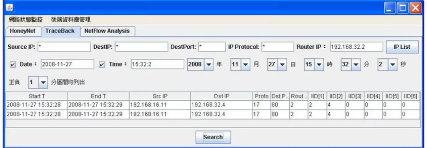
the correct Traceroute p ng of all equ S 254 255. 255. 1 255. 2 255. 255. 254 255. 254 255. 4 255. 7 255. 2 255. 33 255. 11 255. 16 255. 2 255. 255. 254 255. 254 255. hree zones. rding to the s. If source ket is masqu We show the ceback by t traceback p process by v uipment Sub-mask 255.255.0 255.255.0 255.255.0 255.255.0 255.255.0 255.255.0 255.255.0 255.255.0 255.255.0 255.255.0 255.255.0 255.255.0 255.255.0 255.255.0 255.255.0 255.255.0 255.255.0 IPM router e records, w IP address ueraded. e GUI for pr traceroute. I process by I victim Gat 192.168 192.168 192.168 192.168 192.168 192.168 192.168 192.168 192.168 rs mark pac we could k belongs to resenting th IP spoofing IPM routers teway X X 8.64.254 8.64.254 8.0.4 X X 8.32.254 8.32.254 8.32.254 X 8.16.254 8.16.254 8.16.254 X X X kets passed know which other zone, he results of g causes the s. d h , f e
- 28-
Figure 18 Traceback process by IPM router
The results are sub-divided into five parts. The first part is the setting of the IPM router.
The IPM router has to set the initial value for the IID number and the region. The IPM router
bases on the setting to decide if the packets need to mark the information. The second part is
the execution of the sniffer. The information that the sniffer gathered is shown in the screen.
The third part is that the database stores the records and controls on the web. The fourth part
is the traceback GUI. The users utilize the GUI to input the conditions and get the records
from one of IPM routers. The last part is the real network performance.
4.4.1. Setting Result
The program we designed could change the variables in the kernel space. We could use
this program to identify the IID number, set the domain region and the marking decision.
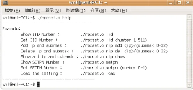
Figure 19 depicts the total commands of the program. The commands are using to change the
variables as show in Figure 20. We can use the file to configure the setting. Figure 21 show
Figure 19 C Figure 20 O - 29-Commands Operations of the IPM of the IPM router router
4
sniff and E mark4.4.2. S
The snifferfer and anal
End time ar king informa F
Sniffer Re
r program yzed the m re the time ation is ana Figure 21 Doesult
is setting i marking info on the buff alyzed by sn - 30-omain contr in each of rmation. Th fer. The ma niffer and serol and file
the interfac he results ar ain part is th eparated into loading ce. The pa re shown in he informat o different f ckets are c n Figure 22 tion of IP O fields. captured by . Start time Option. The y e e
4
the d in the4.4.3. D
The sniffer database. Th e “tam” tab Figure 2Database
r captures th he table info le. 22 Packet inResult
he marking ormation is - 31-nformation information shown by p gathered fr n and sends phpMyAdmrom the snif
s the inform min. Figure ffer mation into 23 depicts the table in the records n s
4
find to tra4.4.4. T
The traceb the informaace back the
Traceback
ack result i ation that th e path so tha Figure 2k Result
is different hey need. Fi at the result - 32-23 Records i from the co igure 24 dep t contains th in the datab onditions. T picts that th he same sou base The users s he user choo urce IP and p elect the co ose Source port. onditions to IP and Port o tThe r Figure 25 d result show Fi Figure 26 Figure 24 T depicts that
w that the sam
igure 25 Tra depicts that Traceback w t the users me destinat aceback wit t the record -
33-with the con
choose Des
ion with the
th the condi ds with the ndition “Sou stination IP e same date ition “Destin same date urce IP and and Date t and differe nation IP an
and the tim d Port” to trace bac ent destinati nd Date” me between ck the path. ion port. n 3:29:47 to . o
3:31:47. Time iss the region Figure 2 n of the valu 6 Traceback - 34-ue chose by k with the c users.
- 35-
Chapter 5.
Conclusion and Future Work
Developing a traceback system that can trace a single packet has been viewed as
impractical due to the tremendous storage requirements of saving packet data. We believe that
the implementation of IPM router is feasible for tracing a single packet. Our system is based
on the observation that the marking information under attack would discover the attack path.
Our system contains three schemes for implementation. In the marking scheme, we
utilize the identifiable number to reduce the space of the option. Additionally, we use MD5
function to hash a number for verification of the fields. Attackers have to try the correct hash
number for masquerading option fields. The marking scheme marks packets according the
domain value of RIP setting. We could choose networks that we want to mark or not. In the
logging scheme, we use buffer space to reduce same records and store them into local
database. Same packet information gathers into one record during a moment. In the traceback
scheme, we could find the area that packets belong to according the records. The records
show the IID information so that we could transfer IID to normal IP address to know the area.
Packets with wrong address are discovered by comparing the area and IP address.
An advantage of our system is that it works in real-time and non-real-time and traces a
single packet. No matter how attackers modify the source IP address, the area that packets
come from can not be hidden.
Commercial firewalls filter out packets by rules set by management. Packets with
marking information may drop by firewall so that the transmission is not complete and failure.
In the future, the marking information may put into other header or fields which are
infrequent used. The database of each IPM router could interact for changing marking
information so that the whole routing path would discover.
IPM would combine with other technique for traceback in wireless network. Access
points (AP) in wireless network should keep the connection information during connecting to
- 36-
- 37-
References
[1] S. Savage, D. Wetherall, A. Karlin, and T. Anderson, “Network Support for IP
Traceback,” IEEE/ACM Transactions on Networking, vol. 9, no. 3, pp. 226-237, 2001.
[2] S. Deering, “Internet Protocol, Version 6 IPv6,” RFC 2460, 1998.
[3] A. Belenky and N. Ansari, “IP Traceback With Deterministic Packet Marking,” IEEE
Communication Letters, vol. 7, pp. 162-164, Apr. 2003.
[4] A. Belenky and N. Ansari, “Tracing multiple attackers with deterministic packet marking
(DPM),” in Proceedings of IEEE Pacific Rim Con. Communications, Computers and
Signal Processing, vol. 1, pp. 49-52, Aug. 2003.
[5] R. Chen, J. Park, and R. Marchany, “RIM: Router Interface Marking for IP Traceback,”
in Proceedings of IEEE GLOBECOM, pp. 1-5, Nov. 2006.
[6] A. Snoeren, C. Partridge, L. Sanchez, C. Jones, F. Tchakountio, B. Schwartz, S. Kent,
and W. Strayer, “Single-Packet IP Traceback,” IEEE/ACM Transactions on Networking,
vol. 10, no. 6, pp. 721-734, 2002.
[7] D. Basheer and G. Manimaran, “Novel hybrid schemes employing packet marking and
logging for IP traceback,” IEEE Trans. Parallel and Distributed Systems, Vol. 17(5), pp.
403– 418, May 2006.
[8] S. Bellovin, M. Leech, and T. Taylor, ICMP Traceback Messages, Internet Draft,
draft-ietf-itrace-04.txt, Feb. 2003.
[9] A. Yaar, A.Perrig, and D.Song, "FIT: Fast Internet Traceback," in Proceedings of
Code Code Code Code Code e 1 mpcset. e 2 mylisten e 3 myd.c .. e 4 Traceba e 5 br_forw c ... ner.c ... ... ack.java .... ward.c ...
Appe
... ... ... ... ... Fi -38-endix A
... ... ... ... ... gure 27 AssA. Cod
... ... ... ... ... sociationdes
... ... ... ... ... ... ... ... ... ... ... 39 ... 46 ... 58 ... 60 ... 68 9 6 0- 39- Code 1 mpcset.c #include <stdio.h> #include <stdlib.h> #include <string.h> #include <syscall.h>
#define RED "\E[31m\E[1m" #define GREEN "\E[32m\E[1m" #define BLUE "\E[34m\E[1m" #define NORMAL "\E[m"
unsigned int reverse_submask(unsigned int num){
int i;
unsigned int submask; submask=0; for(i=31;i>=0;i--){ if(num%2==1) submask += 1<<i; num = num>>1; } return submask; } void savefile(){ FILE *output; int i; int temp; if((output=fopen("mpc.config","w+"))==NULL){ printf("File mpc.config is not writeable!\n"); return;
}
// save IID first
// save SETPN second // save RIP records
fprintf(output,"%d\n",syscall(__NR_getIID)); fprintf(output,"%d\n",syscall(__NR_getSETPN)); temp = syscall(__NR_getCNT); for(i=1;i<=temp;i++) fprintf(output,"%d/%d\n",syscall(__NR_getRIP,i),syscall(__NR_getSUB,i)); fclose(output); } void loadfile(){ FILE *input; int cnt; int iid; int setpn;
- 40-
unsigned int submask;
if((input=fopen("/home/wnl/mpc.config","r"))==NULL){
fprintf(stderr,RED"File mpc.config is not found!\n"NORMAL); exit(-1);
}
// read IID first
if(fscanf(input,"%d\n",&iid)==EOF){
fprintf(stderr,RED"File mpc.config is not correct context!\n"NORMAL); fclose(input);
exit(-1); }
if(iid<1 || iid>511){
fprintf(stderr,RED"File mpc.config is not correct context!\n"NORMAL); fclose(input);
exit(-1); }
syscall(__NR_setIID,iid); // read SETPN second
if(fscanf(input,"%d\n",&setpn)==EOF){
fprintf(stderr,RED"File mpc.config is not correct context!\n"NORMAL); fclose(input);
exit(-1); }
if(setpn<0 || setpn>1){
fprintf(stderr,RED"File mpc.config is not correct context!\n"NORMAL); fclose(input);
exit(-1); }
syscall(__NR_setSETPN,setpn); // clean RIP all records
syscall(__NR_setCNT,0); cnt=0;
// read RIP records
while(fscanf(input,"%d/%d\n",&ip,&submask)!=EOF){ cnt++; syscall(__NR_setRIP,ip,cnt); syscall(__NR_setSUB,submask,cnt); syscall(__NR_setCNT,cnt); } fclose(input);
printf(GREEN"Load mpc.config is finished!\n"NORMAL); }
void IID(unsigned int iid){ if(iid < 1 || iid > 511){
fprintf(stderr,RED"IID Number out of range (1-511)\n"NORMAL); exit(-1);
- 41-
syscall(__NR_setIID,iid);
printf(GREEN"IID = %d\n"NORMAL,syscall(__NR_getIID)); savefile();
}
void RIP(int modes,int argc,char **argv){
char *ip_str;
char *submask_str;
unsigned int ip; unsigned int temp;
int count;
int num;
unsigned int submask; unsigned int submask_2;
// param[0] = add, del or show if(modes==1){
// add
if(argc<2){
fprintf(stderr,RED"Too few parameter: rip add <ip/submask>\n"NORMAL);
exit(-1); }
// divide ip and submask ip_str=strtok(argv[1],"/"); submask_str=strtok(NULL,"/"); // deal with IP ip_str=strtok(ip_str,"."); ip = 0; count = -8; while(ip_str != NULL){ count += 8; temp = atoi(ip_str); if(temp > 255 || temp < 0){
fprintf(stderr,RED"Error : IP address is not correct!\n"NORMAL);
exit(-1); } ip += (temp << count); ip_str = strtok(NULL,"."); } if(count != 24){
fprintf(stderr,RED"Error : IP address is not correct!\n"NORMAL); exit(-1);
}
// deal with submask
submask_2 = atoi(submask_str);
submask=0;
while(submask_2>0){ submask = submask*2 + 1;
- 42-
submask_2--; }
temp = syscall(__NR_getCNT);
if(temp>=30){
fprintf(stderr,RED"Error : The records are full! Please delete record first!\n"NORMAL); exit(-1); } temp++; syscall(__NR_setRIP,ip,temp); syscall(__NR_setSUB,submask,temp); syscall(__NR_setCNT,temp); savefile();
printf(GREEN"Add the record into RIP!\n");
printf("IP:%d.%d.%d.%d\t",ip&0xFF,ip>>8&0xFF,ip>>16&0xFF,ip>>24&0xFF); printf("submask:%08X\n"NORMAL,reverse_submask(submask));
}else if(modes==2){
// del
if(argc<2){
fprintf(stderr,RED"Too few parameter: rip del <ip/submask>\n"NORMAL); exit(-1);
}
// divide ip and submask ip_str=strtok(argv[1],"/"); submask_str=strtok(NULL,"/"); // deal with IP ip_str=strtok(ip_str,"."); ip = 0; count = -8; while(ip_str != NULL){ count += 8; temp = atoi(ip_str); if(temp > 255 || temp < 0){
fprintf(stderr,RED"Error : IP address is not correct!\n"NORMAL);
exit(-1); } ip += (temp << count); ip_str = strtok(NULL,"."); } if(count != 24){
fprintf(stderr,RED"Error : IP address is not correct!\n"NORMAL); exit(-1);
}
// deal with submask
submask_2 = atoi(submask_str);
submask=0;
while(submask_2>0){ submask = submask*2 + 1;
- 43-
submask_2--; }
temp = syscall(__NR_getCNT);
//search the records
num = 1; while(temp >= num){ if(syscall(__NR_getRIP,num)==ip && syscall(__NR_getSUB,num)==submask){ break; } num++; } if(num>temp){
fprintf(stderr,RED"Error : The record is not found!\n"NORMAL); exit(-1); } ip=syscall(__NR_getRIP,temp); submask=syscall(__NR_getSUB,temp); syscall(__NR_setRIP,ip,num); syscall(__NR_setSUB,submask,num); temp--; syscall(__NR_setCNT,temp); savefile();
printf(GREEN"Succeed! Delete the record from RIP!\n"NORMAL);
}else if(modes==3){
// show
temp = syscall(__NR_getCNT);
printf(GREEN"The records(Total:%d):\n",temp);
for(num=1; num<=temp; num++){
ip=syscall(__NR_getRIP,num); submask=syscall(__NR_getSUB,num); printf("IP:%d.%d.%d.%d\t",ip&0xFF,ip>>8&0xFF,ip>>16&0xFF,ip>>24&0xFF); printf("submask:%08X\n",reverse_submask(submask)); } printf(NORMAL); } }
void SETPN(unsigned int setpn){ if(setpn < 0 || setpn > 1){
fprintf(stderr,RED"SETPN Number out of range (0-1)\n"NORMAL); exit(-1); } syscall(__NR_setSETPN,setpn); savefile(); printf(GREEN"SETPN = %d\n"NORMAL,setpn); }
- 44-
int main(int argc, char **argv) { char *cmds[]={"iid","rip","setpn","load","help"}; char *ripcmds[]={"add","del","show"}; int modes,ripmodes; if(argc < 2) {
fprintf(stderr,RED"%s <execute command> <parameter>\n"NORMAL, argv[0]);
return -1; } if(!strcasecmp(cmds[0],argv[1])){ // iid modes=1; }else if(!strcasecmp(cmds[1],argv[1])){ // rip modes=2; }else if(!strcasecmp(cmds[2],argv[1])){ // setpn modes=3; }else if(!strcasecmp(cmds[3],argv[1])){ // load config loadfile(); return 0; }else if(!strcasecmp(cmds[4],argv[1])){ // help printf("---\n"); printf("Example:\n");
printf("\tShow IID Number : %s iid\n",argv[0]);
printf("\tSet IID Number : %s iid <number 1-511>\n",argv[0]); printf("\tAdd ip and submask : %s rip add <ip>/<submask
0-32>\n",argv[0]);
printf("\tDelete ip and submask : %s rip del <ip>/<submask 0-32>\n",argv[0]);
printf("\tShow all ip and submask : %s rip show\n",argv[0]); printf("\tShow SETPN Number : %s setpn\n",argv[0]);
printf("\tSet SETPN Number : %s setpn <number 0-1>\n",argv[0]); printf("\tLoad the setting : %s load\n",argv[0]);
printf("---\n");
return 0;
}else{
fprintf(stderr,RED"%s <execute command> <parameter>\n"NORMAL, argv[0]); fprintf(stderr,RED"%s %s:Unknow\n"NORMAL, argv[0], argv[1]);
return -1;
}
switch(modes){
case 1:
- 45- // show IID printf(BLUE"IID = %d \n"NORMAL,syscall(__NR_getIID)); return 0; }else{ IID(atoi(argv[2])); } break; case 2: if(argc <3){
fprintf(stderr,RED"%s rip [\"add <ip>/<submask 0-32>\" | \"del <ip>/<submask 0-32>\" | \"show\"]\n"NORMAL, argv[0]);
return -1; } if(!strcasecmp(ripcmds[0],argv[2])){ // add ripmodes=1; }else if(!strcasecmp(ripcmds[1],argv[2])){ // del ripmodes=2; }else if(!strcasecmp(ripcmds[2],argv[2])){ // show ripmodes=3; }else{
fprintf(stderr,RED"%s rip [\"add <ip>/<submask 0-32>\" | \"del <ip>/<submask 0-32>\" | \"show\"]\n"NORMAL, argv[0]);
fprintf(stderr,RED"%s rip %s:Unknow\n"NORMAL, argv[0],argv[2]);
return -1; } RIP(ripmodes,argc-2,&argv[2]); break; case 3: if(argc <3){ // show SETPN printf(BLUE"SETPN = %d \n"NORMAL,syscall(__NR_getSETPN)); return 0; }else{ SETPN(atoi(argv[2])); } break; default: break; } return 0; }
- 46- Code 2 mylistener.c #include <errno.h> #include <stdio.h> #include <stdlib.h> #include <string.h> #include <sys/socket.h> #include <fcntl.h> #include <netpacket/packet.h> #include <net/if.h> #include <net/if_arp.h> #include <netinet/in.h> #include <net/ethernet.h> #include <netinet/ether.h> #include <netinet/ip.h> #include <netinet/udp.h> #include <netinet/tcp.h> #include <linux/if_ether.h> #include <arpa/inet.h> #include <sys/ioctl.h> #include <unistd.h> #include <time.h> #include <sys/time.h> #include <signal.h> #include <mysql/mysql.h> #include <linux/unistd.h>
#define RED "\E[31m\E[1m"
#define GREEN "\E[32m\E[1m"
#define YELLOW "\E[33m\E[1m"
#define BLUE "\E[34m\E[1m"
#define NORMAL "\E[m"
#define MAX_BUFFER 100 // max number of records #define MAX_SECOND 60.0 // Time of life for each record
// The option from internet without editing, only get the infomation and copy to this structure
typedef struct Tempop {
unsigned short option:8, length:8; unsigned char ops[6];
} Tempop;
// The option corss Tempop structure and get the correct information to each field typedef struct Myop {
unsigned short option:8, length:8; unsigned short hash;
unsigned short IID[6]; }Myop;
- 47-
// Full information for each packet typedef struct ops {
time_t Ts,Te; // time of first packet crossed and time of last packet crossed (Same info.)
unsigned int source_IP; // Source IP unsigned int dest_IP; // Destination IP unsigned short protocol; // IP Protocol unsigned int source_PORT; // Source Port unsigned int dest_PORT; // Destination Port unsigned short IID_Num; // Number of IIDs Myop op; // Packet Option Information
struct ops *next,*pre; // Linking list according to time (H:earlist T:latest) struct ops *IID_next,*IID_pre; // Linking list according to number of IIDs }OPs;
// Global variables
int RecordNum; // count number of information
OPs *IIDListH[6], *IIDListT[6]; // IID linking list Head and Tail OPs *TimeListH,*TimeListT; // Time linking list Head and Tail MYSQL mysql;
char *host; char *database; char *user; char *passwd; unsigned int IID;
int Get_IfaceIndex(int fd, const char* interfaceName) {
struct ifreq ifr;
if (interfaceName == NULL) { return -1; } memset(&ifr, 0, sizeof(ifr)); strcpy(ifr.ifr_name, interfaceName);
if (ioctl(fd, SIOCGIFINDEX, &ifr) == -1) {
printf("RED ioctl error\n");
return -1;
}
return ifr.ifr_ifindex;
}
int set_Iface_promisc(int fd, int dev_id) {
struct packet_mreq mr;
memset(&mr,0,sizeof(mr)); mr.mr_ifindex = dev_id;