國
立
交
通
大
學
網路工程研究所
碩
士
論
文
利用封包聚合機制增進 IEEE 802.11 無線電感知網路
之效能
Using Frame Aggregation Mechanism to Improve the Performance of
IEEE 802.11 Cognitive Radio Network
研 究 生:王柏凡
指導教授:王協源 教授
I
利用封包聚合機制增進 IEEE 802.11 無線電感知網路之效能
Using Frame Aggregation Mechanism to Improve the Performance of
IEEE 802.11 Cognitive Radio Network
研 究 生:王柏凡
Student:Po-Fan Wang
指導教授:王協源 Advisor:Shie-Yuan Wang
國立交通大學
網路工程研究所
碩士論文
A ThesisSubmitted to Institute of Network Engineering College of Computer Science
National Chiao Tung University in partial Fulfillment of the Requirements
for the Degree of Master
in
Computer Science October 2012
Hsinchu, Taiwan, Republic of China
中華民國一百零一年十月
II
利用封包聚合機制增進 IEEE 802.11 無線電感知網路之效能
學生:王柏凡 指導教授:王協源 教授
國立交通大學 網路工程研究所 碩士班
摘 要
隨著科技進步以及個人通訊裝置的興起,近年來無線網路的應用在種類
以及數量上蓬勃發展,現有的頻帶多採用固定劃分的方式,由業者向政府
機構申請職執照後發配,有研究指出此種固定劃分的機制造成整體的頻譜
使用效率不佳,原因是部分所劃分出去的頻帶使用率不高,然而其他無執
照的使用者並不能使用該頻帶。整體而言,可用於傳輸之無線網路頻譜逐
漸感到不足,因此,近年來無線電感知網路的領域蓬勃發展,此技術的提
出宗旨在於更有效率的利用無線頻譜,其中有一部份的機制可以達到在不
干擾已劃分之頻段的主要使用者的情況下進而使用該頻段。
本篇論文主要繼承前人在 IEEE 802.11 無線電感知網路的研究成果,進
行在更高資料傳輸率以及更新的主要使用者情況下進行驗證,並利用 IEEE
802.11n 封包聚合機制來改善現有機制的效能並且透過更新版的 Estinet 網路
模擬器來驗證效能的提升以及對主要使用者的影響。
關鍵字:無線感知網路、網路模擬器、IEEE 802.11n 封包聚合機制
III
Using Frame Aggregation Mechanism to Improve the Performance of
IEEE 802.11 Cognitive Radio Network
Student: Po-Fan Wang Advisor: Shie-Yuan Wang
Department of Network Engineering
National Chiao Tung University
ABSTRACT
The concept of cognitive radio (CR) has become more and more popular and important due to the limitation of wireless bandwidth. The current wireless spectrum policy separates the wireless spectrum into many separated spectra and defines them into licensed band or non-licensed band. However, a research shows that the usage of licensed spectrum is less than 25%, which is very inefficient. In a CR network, the CR users are allowed to use the empty spectra in frequency, time and space under the constraints of not interfering with the primary users. The CR approach has a great potential to improve the utilization of licensed spectrum. In this thesis, we follow the previous research of an 802.11 Cognitive Radio Network and use the IEEE 802.11n frame aggregation mechanism to improve the performance and evaluate the result on Estinet network simulator. In our simulation result, we show that the frame aggregation mechanism successfully improves the performance of previous work and the frame aggregation mechanism does not increase the influence to PUs.
IV
誌 謝
首先感謝我的指導教授王協源老師這兩年來的細心指導,以及給我在學
術上的訓練,並讓我從一進研究所就開始有機會能夠將研究成果發表至國
際期刊,這些都是我在人生中重要的成就。此外,感謝三位口試委員李端
興老師、吳曉光老師、趙禧綠老師擔任我的口試委員並給予許多很好的建
議以及指導,使我的論文更完整、豐富。
感謝所有 NSL 實驗室的成員,感謝上一屆的學長們在畢業最後關頭給了
我畢業的勇氣與信心,感謝同屆同學豐富了我兩年的實驗室生活,與你們
健身聊天將是我一輩子的回憶,感謝強者學弟妹帶來認真的風氣,讓實驗
室的氣氛止跌回升,感謝碩二下時來自對岸的交換生,讓我在學生生涯的
最後階段能夠有精采的回憶。
最重要的是感謝我的父母,從小到大當我堅實的後盾以及溫暖的避風港,
並在研究所的最後階段毫無保留的支持我,讓我無後顧之憂地向前衝刺。
感謝待了六年的交大以及新竹,我畢業了!
王柏凡 2012.10 秋
V
目 錄
中 文 摘 要 ... I 英 文 摘 要 ... III 目 錄 ... V 圖 目 錄 ... VII 表 目 錄 ... XI Chapter 1 Introduction ... 1Chapter 2 Background Introduction to Cognitive Radio Network ... 3
2.1. Introduction to Cognitive Radio Network ... 3
2.2. Throughput Limitation of 802.11 WLAN ... 4
2.3. IEEE 802.11n Frame Aggregation and Block ACK Mechanisms ... 6
2.3.1. Aggregated-Mac Service Data Unit ... 7
2.3.2. Aggregated-Mac Protocol Data Unit ... 8
2.3.3. Two-Level Aggregation (TLA) ... 10
2.3.4. Block ACK Mechanism ... 11
Chapter 3 Related work ... 13
3.1. Related work I: On Synchronized Channel Sensing and Accessing for Cognitive Radio Users in IEEE 802.11 Wireless Networks (Ori-MAC) ... 13
3.2. Related work II: Enhanced MAC Protocol for Cognitive Radios over IEEE 802.11 Networks (Uni-MAC) ... 19
3.3. Related work III: Bi-directional Cognitive Radio MAC Protocol for Supporting TCP Flows (Bi-MAC) ... 24
VI
3.4. Related work IV: An IEEE 802.11 cognitive radio MAC protocol with dynamic
bandwidth allocation capabilities. ... 30
Chapter 4 Motivation ... 40
Chapter 5 Proposed Frame-aggregated CR Mac protocol (FA-MAC) ... 42
5.1. Migration of Uni-MAC and ABi-MAC over Estinet Network Simulator ... 43
5.2. New Dynamic Bandwidth Allocation Process (NDBA)... 44
5.3. New Bandwidth Negotiation Process ... 47
5.4. Implementation of Aggregated-Mac Service Data Unit (A-MSDU) Mechanism 50 5.5. Implementation of Aggregated-Mac Protocol Data Unit (A-MPDU) Mechanism 52 5.6. Implementation of Block ACK Operation ... 57
Chapter 6 Performance evaluation ... 58
6.1. Simulation Settings ... 59
6.2. The Improvement of Maximum Throughput of FA-MAC ... 62
1. 6.3. . The Effect on Primary Users’ Throughput and Packet Transmission Delay from FA-MAC ... 70
6.4. Summary ... 83
Chapter 7 Conclusion ... 84
VII
圖 目 錄
Figure 2.1 Normalized overhead under different data rate and payload in [5] ... 5
Figure 2.2 The Maximum Throughput and the Throughput Upper Limit for IEEE 802.11a in [5] ... 6
Figure 2.3 Aggregated-Mac Service Data Unit ... 8
Figure 2.4 Aggregated-Mac Protocol Data Unit... 10
Figure 2.5 Two-Level Aggregation ... 11
Figure 2.6 Illustration of Block ACK operation. ... 12
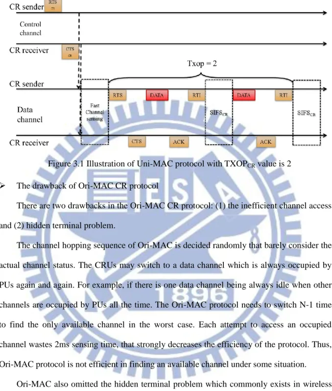
Figure 3.1 Illustration of Uni-MAC protocol with TXOPCR value is 2 ... 18
Figure 3.2 Illustration of Hidden Terminal Problem ... 19
Figure 3.3 Illustration of AR update procedure and Calculation of the Availability Index ... 20
Figure 3.4 Frame format of RTSCR in Uni-AMC ... 21
Figure 3.5 Frame format of CTSCR in Uni-AMC ... 21
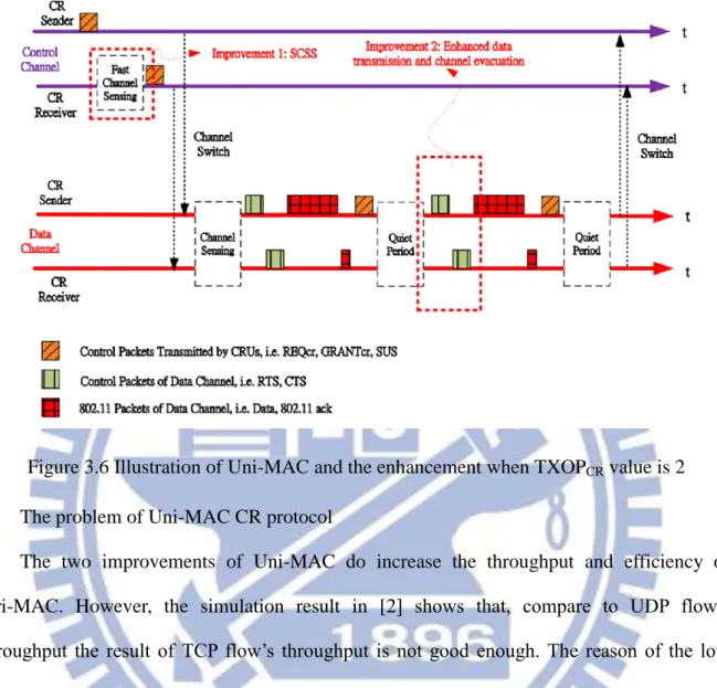
Figure 3.6 Illustration of Uni-MAC and the enhancement when TXOPCR value is 2 ... 24
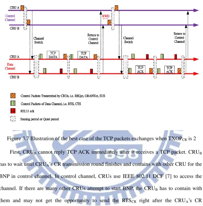
Figure 3.7 Illustration of the best case of the TCP packets exchanges when TXOPCR is 2 .... 26
Figure 3.8 Illustration of a bad case of the TCP packets exchanges when TXOPCR is 2 ... 27
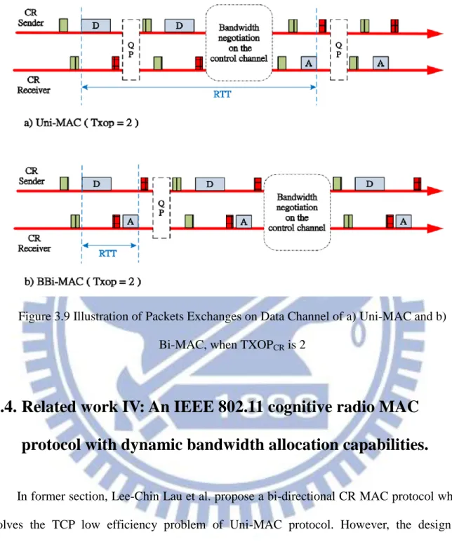
Figure 3.9 Illustration of Packets Exchanges on Data Channel of a) Uni-MAC and b) Bi-MAC, when TXOPCR is 2... 30
Figure 3.10 Illustration of Message Exchanges on Data Channel of Bi-MAC with Bi-directional Bandwidth Reservation when TXOPCR = 3 ... 33
Figure 3.11 Illustration of inappropriate TI setting of Bi-MAC with Bi-directional Bandwidth Reservation ... 35
VIII
Figure 3.12 Frame Format of the control packet RTSCR of ABi-MAC ... 37
Figure 3.13 Frame Format of the control packet CTSCR of ABi-MAC ... 37
Figure 5.1 Illustration of IEEE 802.11 DCF implementation on NCTUns and Estinet. ... 44
Figure 5.2 Illustration of NDBA without switching the sender/receiver ID when TXOPCR is 6 ... 46
Figure 5.3 Switching Sender/Receiver ID Case of NDBA when TXOPCR is 4 ... 47
Figure 5.4 Illustration of Bandwidth Negotiation Process ... 49
Figure 5.5 Illustration of New Bandwidth Negotiation Process... 50
Figure 5.6 Illustration of CRU Protocol Modules Stack with A-MSDU module. ... 52
Figure 5.7 The Structure of frame_item And frame_pack. ... 54
Figure 5.8 Illustration of A-MPDU frame aggregation and NDBA with asymetric flow. ... 55
Figure 5.9 Illustration of A-MPDU And Block ACK Operation Over Uni-MAC (TXOPCR = n) ... 56
Figure 5.10 Illustration of A-MPDU and Block ACK operation over ABi-MAC with symmetric traffic flow (TXOPCR = 6) ... 56
Figure 5.11 The Structure of frame_item and frame_pack... 57
Figure 6.1 Simulation Case 1 for Maximum Throughput Evaluation ... 60
Figure 6.2 Simulation case 2 for evaluating the influence to PUs ... 61
Figure 6.3 Maximum UDP Throughput of Uni-MAC with different Frame Aggregation Mechanism (with UDP payload 1450 bytes) ... 64
Figure 6.4 Maximum TCP Throughput of Uni-MAC with different Frame Aggregation Mechanism ... 65
Figure 6.5 Maximum UDP Throughput of ABi-MAC with different Frame Aggregation Mechanism (with UDP payload 1450 bytes) ... 66
IX
Figure 6.6 Maximum TCP Throughput of ABi-MAC with different Frame Aggregation
Mechanism ... 68
Figure 6.7 Maximum Application Layer UDP Throughput of ABi -MAC with different Bit Error Rates (with UDP payload 1450 bytes, TXOPCR = 10) ... 69
Figure 6.8 Maximum Application Layer TCP Throughput of ABi-MAC with different Bit Error Rates (TXOPCR = 10) ... 70
Figure 6.9 UDP Throughput of CRU with 30% PU Load ... 73
Figure 6.10 PU’s Average Packet Delay Time (30% PU Load) ... 73
Figure 6.11 TCP Throughput of CRU with 30% PU Load ... 74
Figure 6.12 PU’s Average Packet Delay Time (30% PU Load) ... 74
Figure 6.13 Application Layer UDP Throughput of ABi-MAC with Different Bit Error Rates (With UDP payload 1450 bytes, TXOPCR = 10) ... 75
Figure 6.14 Application Layer TCP Throughput of ABi-MAC with different Bit Error Rates (TXOPCR = 10) ... 75
Figure 6.15 UDP Throughput of CRU with 50% PU Load ... 77
Figure 6.16 PU’s Average Packet Delay Time (50% Load) ... 77
Figure 6.17 TCP Throughput of CRU with 50% PU Load ... 78
Figure 6.18 PU’s Average Packet Delay Time (50% Load) ... 78
Figure 6.19 Application Layer UDP Throughput of ABi-MAC with different Bit Error Rates (UDP payload 1450 bytes, TXOPCR = 10, 50% PU Load) ... 79
Figure 6.20 Application Layer TCP Throughput of ABi-MAC with different Bit Error Rates (TXOPCR = 10, 50% PU Load) ... 79
Figure 6.21 The Throughput of PUs with the effect of CRUs (80% PU Load) ... 81
Figure 6.22 UDP Throughput of CRU with 80% PU Load ... 81
X
Figure 6.24 The Throughput of PUs with the effect of CRUs (80% PU Load) ... 82 Figure 6.25 TCP Throughput of CRU with 80% PU Load ... 82 Figure 6.26 PU’s Average Packet Delay Time (80% PU Load) ... 82
XI
表 目 錄
Table 6.1 The abbreviation of different CR MACs and Frame aggregation Mechanisms ... 58
Table 6.2 The Parameter Setting of CR MAC protocol ... 59
Table 6.3 Traffic Flows Setting of Case 1 ... 60
Table 6.4 PUs Traffic Flow and the configuration command... 61
Table 6.5 The Network Flow applied to CRUs ... 62
Table 6.6 The Improvement Of Maximum UDP Throughput When Different Frame Aggregation Mechanism Is Applied. (in percentage) ... 64
Table 6.7 The Improvement Of Maximum TCP Throughput When Different Frame Aggregation Mechanism Is Applied (in percentage) ... 65
Table 6.8 The Improvement of Maximum UDP Throughput When Different Frame Aggregation Mechanism Is Applied (in percentage) ... 66
Table 6.9 The Improvement Of Maximum TCP Throughput When Different Frame Aggregation Mechanism Is Applied. (in percentage) ... 68
Table 6.10 The PU’s Throughput of 30% Load with the effect of CRUs (KB/s)... 73
Table 6.11 The PU’s Throughput of 30% Load with the effect of CRUs (KB/s) ... 74
Table 6.12 The PU’s Throughput of 50% Load with the effect of CRUs (KB/s)... 77
1
Chapter 1 Introduction
The concept of cognitive radio (CR) has become more and more popular and important due to the limitation of wireless bandwidth. In [13], the authors show that the usage of licensed spectrum is less than 25%, which is very inefficient. In a CR network, the secondary/unlicensed users (CRUs) are allowed to use the empty spectra in frequency, time and space under the constraints of not interfering with the primary/licensed users (PUs). The CR approach has a great potential to improve the utilization of licensed spectrum. For licensed band Cognitive Radio, there are two important standards: IEEE 802.22 [9] and ECMA-392 [10]. In contrast, IEEE 802.15.2 working group [12] which is working on the coexistence mechanisms of IEEE 802.15 and IEEE 802.11 is one of the unlicensed-band Cognitive Radio.
This thesis is an extension of the work done by [2], [3] and [4]. Shie-Yuan Wang et al. [2] proposed a CR MAC protocol that allows CRUs to access the idle period of an IEEE 802.11 network with a Smart Channel Sensing Scheme and the protection from hidden terminal. Through extensive simulations, Shie-Yuan Wang et al. found that the Transmission Control Protocol (TCP) did not perform well under their extended work. Lee-Chin Lau et al. in [3] and [4] proposed a Bi-directional CR MAC protocol to solve the TCP problem. However, they use old fashion IEEE 802.11b stations as PUs and the data rate applied in the simulation is 2 Mbps. We think those work should be examined and verified under the conditions of using higher data rate and using a more advanced version of IEEE 802.11 stations as PUs.
2
Furthermore, we consider an improvement to enhance the efficiency of CR-MAC protocol through frame aggregation mechanism which is proposed in IEEE 802.11n [8]. The frame aggregation mechanism is already proved that it does improve the efficiency of IEEE 802.11 [6]. We can expect that frame aggregation mechanism could also enhance the efficiency of CR-MAC protocol. In this paper, we implement the frame aggregation mechanism on both Uni-MAC [2] and ABi-MAC [4] to increase the available throughput and analyze the effects of the enhancement on PUs.
The remainder of this dissertation is organized as follows. We will present some background knowledge in Chapter 2. In Chapter 3, the major related work is elaborated. The motivation is mentioned in Chapter 4 and the design and implementation of frame aggregation mechanism on Uni-MAC and ABi-MAC is explained in Chapter 5. Later in Chapter 6, we use the Estinet network simulator to verify our design and see the effect of frame aggregation mechanism on Uni-MAC and ABi-MAC. Finally, we will present our conclusion in Chapter 7.
3
Chapter 2 Background Introduction to
Cognitive Radio Network
2.1. Introduction to Cognitive Radio Network
Recently, the concept of cognitive radio (CR), which was first introduced by Joseph Mitola III [9], has become more and more popular and important due to the limitation of wireless bandwidth. The current wireless spectrum policy separates the wireless spectrum into many separated spectra and defines them into licensed band or non-licensed band. One can tell the meaning by name that licensed band is only allowed for licensed users in order to guarantee the application and communication quality on it. On the other hand, non-licensed band is free for everyone but the user on it has to contend with each other for the bandwidth. An example for licensed band is Wireless TV band (54 MHz and 806 MHz in U.S.) and an example for non-licensed band is 2.450 GHz for WLAN.
Unlike the current policy, cognitive radio has the ability to detect available channel in wireless medium, switch itself to the channel, and changes the transmission and reception parameter automatically so that more wireless communications may run concurrently in a given spectrum band at a place.
For licensed band Cognitive Radio, there are two important standards: IEEE 802.22 [10] and ECMA-392 [11]. Both of them defined the MAC and PHY specification of Cognitive Radio network that operate on TV White Space (this unused TV spectrum is often termed as
4
“white spaces”) of Wireless TV band. In contrast with licensed band Cognitive Radio, there is also Unlicensed-Band Cognitive Radio which can only utilize unlicensed parts of the radio frequency (RF) spectrum. An example of unlicensed-band Cognitive Radio is IEEE 802.15.2™-2003 [12], which defines on the coexistence mechanisms of IEEE 802.15 and IEEE 802.11.
2.2. Throughput Limitation of 802.11 WLAN
In the last decade, wireless network technology has changed our daily life significantly. One of the most popular wireless networks is IEEE 802.11 wireless local area network (WLAN). Its success is due to some good characteristics such as mobility, flexibility, and low cost. Although the original IEEE 802.11 specification provides only 2 Mb/s date rate, the later IEEE 802.11b, and 802.11a/g specifications provide up to 11 Mb/s and 54 Mb/s data rates. However, the improvement of physical layer data rates does not increase the user-level throughput due to the design of IEEE 802.11 MAC protocol. In [5], the authors analyze the overhead of IEEE 802.11 MAC under different data rate at different payload sizes. They indicate that the overhead is the major issue of inefficient MAC includeing headers (MAC header, frame check sequence [FCS], and PHY header), interframe spaces (IFSs), backoff time, and ACKs. They defined overhead as the difference between data rate and throughput and defined normalized overhead as overhead divided by data rate. Figure 2.1 shows that the normalized overhead reaches over 90% at 50 Mbps data rate when the payload size is 100 bytes and the normalized overhead still reaches over 40% at 50 Mbps data rate when the payload size is 1,500 bytes.
Figure 2.2 shows the maximum throughput and throughput upper limit of IEEE 802.11a. The throughput upper limit (TUL) is defined as the maximum throughput when the raw data
5
rate goes infinitely high. In Figure 2.2, the maximum throughput reaches about 30 Mbps with the 54 Mbps data rate and 1,500 bytes payload. However, the maximum throughput is about only 54 Mbps with the 216 Mbps data rate and 1,500 bytes payload. In this case, the used data rate is four times higher but the throughput improvement is less than twice. In order to overcome the overhead issue of IEEE 802.11 MAC, IEEE 802.11n is proposed with several efficient MAC enhancements, which that we will address in the following sections.
6
2.3. IEEE 802.11n Frame Aggregation and Block ACK
Mechanisms
Before the introduction of frame aggregation mechanisms, there are some terms that readers should know. The IEEE Std 802.11™-2007 [7] defines:
Medium access control (MAC) service data unit (MSDU): information that is delivered as a unit between MAC service access points (SAPs).
Medium access control (MAC) protocol data unit (MPDU): the unit of data exchanged between two peer MAC entities using the services of the physical layer (PHY).
Figure 2.2The Maximum Throughput and the Throughput Upper Limit for IEEE 802.11a in [5] Y. Xiao, “IEEE 802.11n: Enhancements for Higher Throughput in Wireless
7
PLCP protocol data unit (PPDU): the actual frame send on the wireless medium.
2.3.1. Aggregated-Mac Service Data Unit
Figure 2.3 illustrates the concept of A-MSDU aggregation. As one can see, this method aggregates the MSDU sending from the upper layer of MAC protocol layer into one big A-MSDU frame. Only those MSDUs that has the same destination address (DA) and source address (SA) as the receiver address (RA) and transmitter address (TA) can be aggregated into one A-MSDU. To completely form an A-MSDU either when the size of the waiting packets reaches the maximal A-MSDU threshold or the maximal delay of the oldest packet reaches a pre-assigned value. After the aggregation, the MSDUs become sub frames of the A-MSDU and send in to mac protocol layer. In the mac protocol layer, an A-MSDU should be encapsulated into a single MPDU. All the A-MSDU sub frames will share the same MAC header after being aggregated into one MPDU. One important point is that an A-MSDU in a MPDU should not be fragmented and the destination address field in mac header of the MPDU carrying an A-MSDU should be set to an individual address. One should know there is a size limitation of A-MSDU. In IEEE 802.11n [8], the maximum size of A-MSDU is ether 3389 bytes or 7935 bytes. A mobile station should not transmit an A-MSDU to another mobile station that exceeds its maximum A-MSDU length capability.
The A-MSDU aggregation technique reduces the overhead of the mac header by using a mac header to all the A-MSDU sub frames. A bigger improvement to the IEEE 802.11 mac protocol is it reduces the transmission overhead by sending the aggregated MSDU together rather than sending them one at a time.
8
2.3.2. Aggregated-Mac Protocol Data Unit
Figure 2.4 illustrates the concept of A-MPDU aggregation. The idea of A-MPDU aggregation is to join multiple MPDU sub frames with a single leading PHY header. The A-MPDU aggregation is done after the MAC header encapsulation process. The A-MPDU aggregation restriction factor doesn’t contain the TID of the MPDU frame which is different from A-MSDU aggregation. Still, all the aggregated MPDUs must be addressed to the same receiver address. There is no waiting time to form an A-MPDU which means an A-MPDU is formed by the packets already in the transmission queue at the aggregation period. The maximum length of an A-MPDU is 65,535 bytes and the maximum number of sub frames that it can hold is 64 because a block ACK bitmap field is 128 bytes in length, where each frame is mapped using two bytes. The two bytes are for the acknowledgement of up to 16 fragments but because A-MPDU does not allow fragmentation, these extra bits are excessive. There is a
9
new variant so called compressed block ACK which has a bitmap field only eight bytes long. One can see there is a set of fields, known as MPDU delimiters in Figure 2.4. The delimiters are inserted before each MPDU and a set of padding bits length from 0 – 3 bytes are added at the tail. The delimiter header is used to define the MPDU position and length inside the aggregated frame. The cyclic redundancy check (CRC) field in the delimiter verifies the authenticity of the 16 preceding bits. The padding bytes are added such that each MPDU is a multiple of four bytes in length, which can assist sub frame delineation at the receiver side. In other words, the MPDU delimiters and PAD bytes determine the structure of the A-MPDU. After the A-MPDU is received, a de-aggregation process initiates. First it checks the MPDU delimiter for any errors based on the CRC value. If it is correct, the MPDU is extracted, and it continues with the next sub frame until it reaches the end of the PSDU. Otherwise, it checks every four bytes until it locates a valid delimiter or the end of the PSDU. The delimiter signature has a unique pattern to assist the de-aggregation process while scanning for delimiters.
10
2.3.3. Two-Level Aggregation (TLA)
Using A-MSDU and A-MPDU together called two-level frame aggregation. Figure 2.5 illustrates the concept of two-level frame aggregation. In first level, when a MSDU coming down from the upper layer, it first buffered in the A-MSDU provisional storage area and check if it satisfy the A-MSDU aggregation condition explained in the previous related subsection. If a data unit satisfied the aggregation condition, it can be compacted in to an A-MSDU. If condition is not satisfy such as TID is different, all these aberrant frames can move to the next level where they will be packed together with any A-MSDUs derived from the first level or other single MSDUs by using A-MPDU aggregation.
A two-level frame aggregation comprises a blend of A-MSDU and A-MPDU over two stages. In Figure 2.5 we illustrate how this new scheme can be achieved. The basic operation is explained as follows: In the first stage, if any MSDUs that are buffered in the A-MSDU Figure 2.4 Aggregated-Mac Protocol Data Unit
11
provisional storage area justify the A-MSDU constraints explained in the previous related subsection, these data units can be compacted into a single A-MSDU. If the TIDs are different, all these aberrant frames can move to the second stage where they will be packed together with any A-MSDUs derived from the first stage or other single MSDUs by using A-MPDU aggregation. However, it must be mentioned that given that the maximum MPDU length for an A-MPDU data frame is limited to 4095 bytes, then A-MSDUs or MSDUs with lengths larger than this threshold cannot be transmitted. Conjointly, any fragments from an A-MSDU or MSDUs also cannot be included in an A-MPDU. In the following section, we evaluate how this synthesis is more efficient in most of the cases than A-MPDU and A-MSDU aggregation operating alone.
2.3.4. Block ACK Mechanism
The Block ACK mechanism is proposed in IEEE 802.11e in [7]. It improves the channel efficiency by saving the time wasted from ACK transmission. The station can transmit several
12
PPDU separated by SIFS and acknowledged by a single aggregated ACK frame, i.e. the Block
ACK (BA) frame. The BA acknowledges the received frame with a bitmap field which
contains the information about the reception of corresponding MPDUs. The BA is reply after receives a block ACK request (BAR) message. Both the block ACK request and block ACK frame are transmitted at the same transmission rate that is used for the corresponding data frame transmission. The A-MPDU aggregation should work with Block ACK mechanism in order to transmit the PPDU frames burst.
13
Chapter 3 Related work
In this chapter, four major related work is introduced in the following section: Related Work I, Related Work II, Related Work III, and Related Work IV. For the simplicity of the article, we call the CR MAC protocol of Related Work I: Ori-MAC, the CR MAC protocol of Related Work II: Uni-MAC, the CR MAC protocol of Related Work III: Bi-MAC and the CR MAC protocol of Related Work IV: ABi-MAC in the following.
3.1. Related work I: On Synchronized Channel Sensing and
Accessing for Cognitive Radio Users in IEEE 802.11 Wireless
Networks (Ori-MAC)
This paper proposed a synchronized channel-sensing and accessing mechanism for cognitive radio users in IEEE 802.11 wireless networks. The mechanism consists of two phases: fast channel sensing and proactive channel vacating. Fast channel sensing mechanism is for a pair of cognitive radio users to find an available channel efficiently; proactive channel vacating mechanism provides the protection of the channel usage of primary users.
New control frames and system parameters:
The authors define three control frames and four parameters:
New control frames:
RTSCR: this control frame is used while a CRU (denoted as CR sender) wants to
14
control frame carry two channel hopping information: initial selected data channel ID and increment-per-hop. The two parameters are introduced in the new parameters section below. RTSCR control frame is sent on control channel only.
CTSCR: this control frame is used for a CR receiver to replay its CR sender that it is
idle and ready to start the channel sensing procedure. CTSCR control frame is also
sent on control channel only.
Ready-To-be-Interrupted (RTI): this control frame is used while CR sender receives an ACK for a CR receiver after a successful packet transmission. CR sender sends a RTI for primary users nearby to claim the data channel if they is data available to send.
New parameters:
Initial selected data channel ID (denoted as Ch(1)): it is the first data channel that selected by CR sender randomly. The CR pair will first switch to this channel to do the channel sensing. Ch(1) is a positive integer, and 1 ≤ 𝐶ℎ(1) ≤ 𝑁.
Increment-per-hop (h): is the hopping parameter for CRUs to switch to other channel. When CR sender and receiver sense PUs signal during the sensing period on Ch(1). The CRUs will switch to the next channel Ch(1) + h. h is smaller than data channel number (N) and h and N are relative primes.
TXOPCR: is the number of frames that a CR sender can send on a data channel.
SIFSCR: is a small time interval between RTI and the next data frame. The function
of SIFSCR is providing opportunities for PUs to claim the channel. When one PU
with data frames to send, it sends out RTS after receiving RTI. CRUs will detect the presence of PUs and return to control channel. The SIFSCR should longer than time
for a PU to sends out the RTS which is set to 10 * SIFS. Fast channel sensing:
15
When a CR sender want to send some data frames to a CR receiver, CR sender should first transmits a RTSCR control frame which carrying the channel hopping information (initial
selected data channel ID and increment-per-hop) to CR receiver. After receiving RTSCR
control frame, CR receiver reply a CTSCR frame to inform CR sender that it is in idle state and
ready to receive data. CR receiver then switch to initial selected data channel Ch(1). CR sender also switch to Ch(1) after receiving the CR receiver’s reply. We call the exchange of RTSCR and CTSCR as Bandwidth Negotiation Process (BNP) in the following sections.
After switching into Ch(1) data channel, Both CR sender and CR receiver start to listen to the channel for 2ms. During this sensing time interval, the CR pair listens to the channel to avoid the interference of PUs’ data transmission. If the data channel is heard idle, CR sender and CR receiver will start the data transmission process. Otherwise, CR sender and CR receiver hop to the next channel and start to sense again. The data transmission process starts with an RTS/CTS exchange between CR sender and CR receiver. This avoids a collision when more than one pair of CRUs switches into same data channel at the same time. The next channel ID is decided by (3-1).
Ch(i + 1) = (Ch(i) + h) mod N, i ≥ 1, (3-1) where Ch(1) is initial selected data channel ID and i mean the ith channel hopping. This function can generate a hopping sequence that going through all data channels without entering any channel repeatedly. For instance, the number of data channel N is 8 (numbered 0-7); Ch(1) and h are 4 and 3, the complete hopping sequence will be [4, 7, 2, 5, 0, 3, 6, 1, 4, 7, 2, …].
After the BNP, a CR pair will try to access each data channel in sequence generated by (3-1) until finding an idle channel and do the data transmission. Otherwise, the CR pair will keep trying the next channel until the CR pair finds one data channel which is not occupied by PUs and other CRUs.
16
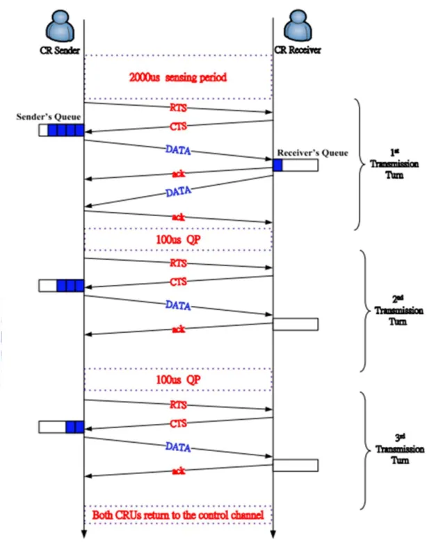
If a CR pair successfully finds an idle data channel after channel sensing, CR sender sends a RTS frame to CR receiver instantly and waits for CR receiver’s reply. Once the CR sender receives the reply successfully, CR sender starts to transmit the data frames one at a time. After receiving the ACK reply from CR receiver, CR sender sends the broadcast RTI frame to one-hop neighboring PUs and wait for SIFSCR time so that PUs has the opportunity
to claim the channel. We called this time interval as Quiet Period (QP). If CR sender receives a RTS from PU, the CR pair then vacates the data channel and hop back to control channel. If no RTS is received, CR sender can transmit another data frame to CR receiver after QP. If no PU claims the data channel after each RTI sent by CR sender, CR sender can transmit upto TXOPCR frames. The RTI control message will inform that if there is more date frame to CR
receiver after RTI and QP. After that, the CR pair need to hop back to control channel even there are more data frames in the queue. If there are still queued frames to send, the CR pair must run the procedure of BNP and fast channel sensing again. We defined the process (a CRU pair start BNP until they hop back to control channel) above as “CR Transmission
Round” in the following of this paper.
Proactive channel vacating:
There are two kind of situations mention above for a CRU pair to vacate the data channel.
The CRU pair already transmitted TXOPCR frames on data channel.
When CRU pair noted there is PU wants to claim the data channel.
For the first situation, the CRU pair stop transmitting/receiving data frames and need to hop back to control channel. The design of proactive channel vacating is focus on the second situation. The authors provide an interruption mechanism and elaborate it by three cases as follow.
17
and QP), a CR sender sends a RTI frame and then waits for SIFSCR long. During this period,
the CRU may hear a RTS from a PU who want to claim the channel. Due to the characteristic of wireless network, there are three cases while a PU sends out a RTS:
Only CR sender overhears the RTS: the CR sender then stops transmitting data and hops back to the control channel. In the meantime, the CR receiver does not receive further data frames, and thus is aware that the CR sender must be interrupted by a potential primary sender. The CR receiver hops back to the control channel, too. If the CR sender still has data for the CR receiver, it generates a new initial data channel ID and increment-per-hop, and sends communication invitation on the control channel.
Only CR receiver overhears the RTS: at this time, the CR receiver is aware of the presence of a primary sender. The CR receiver hops back to the control channel. Though the CR sender keeps sending data frames, it does not receive any ACKs from the CR receiver. Therefore, the CR sender vacates the occupied data channel and hops back to the control channel, too.
Both CR sender and CR receiver overhear: both CR sender and CR receiver noted the presence of PU, and hop back to control channel.
With the design of proactive channel vacating mechanism, the CRUs can reduce the interference to PUs. After all, not interference PUs is one of the main sprit of cognitive radio.
18
The drawback of Ori-MAC CR protocol
There are two drawbacks in the Ori-MAC CR protocol: (1) the inefficient channel access and (2) hidden terminal problem.
The channel hopping sequence of Ori-MAC is decided randomly that barely consider the actual channel status. The CRUs may switch to a data channel which is always occupied by PUs again and again. For example, if there is one data channel being always idle when other channels are occupied by PUs all the time. The Ori-MAC protocol needs to switch N-1 time to find the only available channel in the worst case. Each attempt to access an occupied channel wastes 2ms sensing time, that strongly decreases the efficiency of the protocol. Thus, Ori-MAC protocol is not efficient in finding an available channel under some situation.
Ori-MAC also omitted the hidden terminal problem which commonly exists in wireless network. Figure 3.2 illustrates the situation that hidden terminal problem might accrue. In this situation, CR sender sends the broadcast RTI and waits for SIFSCR after transmit the first data
frames successfully. At this moment, PU sender start to claim the channel by sending the RTS which CR sender cannot hear. After waiting SIFSCR time, CR sender still considers the
channel is idle and starts to transmit the data frame. This will cause that following frame Figure 3.1 Illustration of Uni-MAC protocol with TXOPCR value is 2
19
transmitted by CR sender to collide with those transmitted by PU sender at the position of CR Receiver. The network flow goodput is greatly affected and the efficiency of Ori-MAC will greatly decrease when hidden terminal existed.
The two drawbacks were improved by the work of Shue-Yuan Wang et al., who proposed a enhanced CR MAC protocol introduced in the following section.
3.2. Related work II: Enhanced MAC Protocol for Cognitive
Radios over IEEE 802.11 Networks (Uni-MAC)
To solve the problems we mentioned in the previous section, Shue-Yuan Wang et al. [2] proposed two improvements to [1]’s Uni-MAC: Smart Channel Selection Scheme (SCSS) and
enhanced data transmission and channel evacuation process. The detail of the two
improvements is stated as follow. Smart Channel Selection Scheme
Figure 3.2 Illustration of Hidden Terminal Problem
20
Shue-Yuan Wang et al. use SCSS to replace function (3-1) in [1] to generate the CRU’s hopping sequence. The SCSS can help CRUs to find the available channel in a better way. There are two phases in SCSS: channel estimation and fast channel sensing.
The channel estimation mechanism helps CRUs to choose the most possibly idle channel by using a 32-bit Availability Record (AR). Each CRU maintains a 32-bit AR for each data channel to record the historical channel availability result. CRU updates AR after each channel sensing opportunity such as fast channel sensing and QP. Before updating an AR, the CRU right-shift the value of the AR by one bit and record the most recently result at the most significant bit (MSB) of AR. The MSB of AR is set to 1 if the sensing result is idle, set to 0 if the sensing result is busy. The AR update process is shown in Figure 3.3.
The Uni-MAC considers the channel is IDLE if it satisfy the following rules:
Overhearing the ACK frame which means a data frame transmission is just finish. Not overhearing any MAC-layer frames which means the channel is unused. The Uni-MAC considers the channel is BUSY if it satisfies the following rules:
Figure 3.3Illustration of AR update procedure and Calculation of the Availability Index
21
Overhearing a RTS or CTS frame which means a PU or CRU is claiming the channel.
Overhearing a data frame which means the channel is using by a PU or CRU.
The new frame format of RTSCR and CTSCR of Uni-MAC is shown in Figure 3.4 and
Figure 3.5. The initial selected data channel ID and increment-per-hop in RTSCR of Ori-MAC
is replaced by “channel_bitmap” field and a new “channel_hop_order_field” is add into CTSCR frame. The definition of the two fields is elaborate as follow:
channel_bitmap: a 16-bit long field which carries a candidate channels list from CR sender to inform CR receiver.
channel_hop_order_field: a 32-bit long field which carry the channel hopping sequence from CR receiver replies to CR sender.
Figure 3.4Frame format of RTSCR in Uni-AMC
Figure 3.5 Frame format of CTSCR in Uni-AMC
22
The candidate channels list is decided by an Availability Index (AI) for each data channel. AI is calculated according to AR, using the following equation:
AI = ∑ 𝑏(𝑖) ∗ 𝑝𝑜𝑠(𝑖)
31
𝑖=0 (3-2)
which i is the index of AR’s bit. The index of MSB is 31and the index of LSB (least significant bit) is 0. The index of other bits is shown in Figure 3.3. b(i) is the value of ith bit and pos(i) is equal to the index value of the bit. There are two AI calculation examples in Figure 3.3 . The bigger AI value means the channel is not often used lately and a better selection for CRU to transmit data.
In Uni-MAC, when a CR sender has data to send, it also performs the fast channel
sensing process. CRU selects the candidate channels according to AI and fills in the candidate
list into “channel_bitmap” field of RTSCR. CR sender then sends out the RTSCR frame to CR
receiver. After receiving the RTSCR, if CR receiver is available to receive data, it will do the
fast channel sensing and reply the channel hopping sequence by “channel_hop_order_field”
in CTSCR. In the fast channel sensing process, the CR receiver switches itself to each selected
data channel, and sense the availability status on that data channel for 100 microseconds. After sensing all selected data channels, it first updates its own AI values for the selected data channels and then determines the best order of channel hopping sequence among the selected data channels.
After RTSCR/CTSCR handshake, the CR pair will hop into the data channel according the
channel hopping sequence decided by AI and fast channel sensing that improve the efficiency by the simulation result of [2].
Enhanced data transmission and channel evacuation process:
The reason of hidden terminal problem of Ori-MAC is because it only performs the RTS/CTS handshake procedure before the first data transmission round. However, the CR
23
sender can transmit up to TXOPCR data frame after RTS/CTS handshake. During the rest of
the CR transmission round, CR pair waits SIFSCR time for QP between two data transmission
round, that providing opportunity for PU to claim the channel. At the QP, if a PU, which is hidden from CR sender, sends a RTS to claim the data channel, the RTS will not be overheard by the CR sender. After QP, CR sender still considers the channel is unused and sends out the data frame to CR receiver. As a result, a data frame collision happen between the CR sender’s data frame and the data frame from PU at CR receiver.
To solve this problem, Uni-MAC performs RTS/CTS handshake procedure before any data transmission round. After QP, CR sender sends a RTS before data transmission. CR receiver will not reply to CR sender’s RTS if it receives a PU (hidden from CR sender) sender’s RTS. Without the reply from CR receiver, CR sender will learn the existence of PUs and hop back to control channel. This enhancement can easily solve the hidden terminal problem. Although the additional RTS/CTS handshake may increases the transmission overhead, it effectively prevents the interference between CRUs and PUs thus significantly increasing the goodput of the network when HTs are present. The enhancement of the Ori- MAC protocol is illustrated in Figure 3.6.
24
The problem of Uni-MAC CR protocol
The two improvements of Uni-MAC do increase the throughput and efficiency of Ori-MAC. However, the simulation result in [2] shows that, compare to UDP flow’s throughput the result of TCP flow’s throughput is not good enough. The reason of the low efficiency of TCP flow and the solution is proposed by Lee-Chin Lau et al. in [3] which will introduce in next section.
3.3. Related work III: Bi-directional Cognitive Radio MAC
Protocol for Supporting TCP Flows (Bi-MAC)
Lee-Chin Lau et al. identified that the major cause of the TCP performance degradation of Uni-MAC protocol that is due to the mechanism of TCP congestion control. This mechanism is employed such that a TCP sender would adjust its packet transmission rate
25
based on the received TCP ACK. The authors propose a Bi-directional Cognitive Radio MAC Protocol (Bi-MAC) which is an extension of the CR MAC protocol proposed by [2]. The point of Bi-MAC is that it can smartly supports either uni-directionally or bi-directionally bandwidth reservation. The enhancements give the better supports of both TCP and two way UDP flows.
We will address the reason of how TCP congestion control influences TCP flow of Uni-MAC protocol in detail and how does Bi-MAC solve this problem in following.
The degradation of TCP throughput of Uni-MAC
Consider a CR network without any PUs and only one CRU pair is transmitting a TCP flow. Let CRUA be TCP sender that transmits the TCP packets continuously. Let CRUB be the
TCP receiver which replies TCP ACKs while receiving TCP packets from CRUA. The
TXOPCR in this case is set to 2.
For the sake of simplicity, we ignore the TCP three way handshake procedures at the beginning of TCP connection between the CR pair. When CRUA start to transmit the TCP
packets, it starts the BNP and sends a RTSCR with the selected channel list to CRUB. After
receiving RTSCR, CRUB performs a 500 us fast channel sensing (100 us pre data channel),
updates AR and replies the selected channel order to CRUA. Then, CRU pair hops to first
selected data channel and start channel sensing for 2 ms. After that, CRUA can transmit two
frames with a 100 us QP after receives the replied 802.11 ACK from CRUB. After receiving
the first TCP packet from CRUA, CRUB starts to generate the TCP ACK. However, with the
design of Uni-MAC protocol, CRUB cannot reply the TCP ACK to CRUA at the first moment.
In order to reply TCP ACK to CRUA, CRUB has to wait for the current CR transmission round
finish and start over from the BNP again. After the BNP, the CRU pair should find an available data channel before CRUB can reply TCP ACK to CRUA. Finally, CRUB can
26
Figure 3.7 illustrates the situation mention above. One can see there are two drawbacks for TCP flow due to the one-way design of Uni-MAC.
First, CRUB cannot reply TCP ACK immediately after it receives a TCP packet. CRUB
has to wait until CRUA’s CR transmission round finishes and contains with other CRU for the
BNP in control channel. In control channel, CRUs use IEEE 802.11 DCF [7] to access the channel. If there are many other CRUs attempt to start BNP, the CRUB has to contain with
them and may not get the opportunity to send the RTSCR right after the CRUA’s CR
transmission round finishes. After BNP, the CRU pair still needs to find an available data channel through fast channel sensing. Although Uni-MAC implements the SCSS which increase the probability for CRU pair to find the available data channel at the first try; it still has a chance to fail and need a second or even a third try. The process mentioned above
decided the round-trip time (RTT) of the TCP flow. In the best case (see Figure 3.7), with
27
no contention and failure during the BNP and SCSS, the RTT time is the summation of data transmission time, QP time, time of BNP and channel sensing time. However, in a bad case (see Figure 3.8), the SCSS may not success at the first try and will costs additional BNP time or channel sensing time. This highly increases the RTT of the TCP flow of CR sender and decrease the performance.
Second, if the receiver’s TCP ACKs arrive at the sender with the same spacing, then the sender can send new data packets at the same rate to avoid overrunning the bottleneck link. It is said that such ACK policy makes the protocol self-clocking because the sender can dynamically adapts its transmission speed to both the speed of the network and the speed of the peer sending TCP ACKs. Since a TCP’s self-clocking depends on the arrival of TCP ACKs at the same spacing with which the receiver generated them, if these TCP ACKs spend any time sitting in queues during their transit through the network, their spacing may be altered. When ACKs arrive closer together than they were sent, the sender might be misled into sending more data than the network can accept, which could led to congestion and loss of
28
eficiency. This is called the ack-compression effect. It has been proven both statistically and experimentally that the ack-compression effect could result in unfairness and reduced overall throughput compared to what could be expected without this effect.
Proposed Bi-MAC protocol in [3]
To solve the problem, the authors propose a design which supports both bi-direction traffic and uni-direction traffic. A 2-bit field is added into RTSCR and CTSCR control frame1.
The extension filed name as Reservation Type (RT), which indicates the bandwidth reservation type for CRU pair in a transmission run. In Bi-MAC, before a CRU transmitting RTSCR or CTSCR, a CRU always checks the head of transmitting queue (HOQ) and set RT in
following rules:
CR sender set RT of RTSCR to 00 if CR sender identifies HOQ is an UDP packet.
This indicates CR sender is issuing a uni-direction UDP flow.
CR sender set RT of RTSCR to 01 if CR sender identifies HOQ is a TCP packet. This
indicates CR sender is issuing a bi-direction TCP flow.
CR receiver set RT of CTSCR to 10 if CR receiver identifies HOQ is not empty. This
indicates CR receiver requesting a bi-direction flow.
CR receiver copies the RT value from received RTSCR to the RT of CTSCR if CR
receiver identifies HOQ is empty. Because the queue of CRU’s is empty, it follows the RT demanded reservation type by CR sender.
In summary, the bandwidth reservation of a CR transmission round is decided by the RT value of CTSCR: 00 means uni-direction bandwidth reservation is demanded by CRU pair and
bi-direction bandwidth reservation is demanded by CRU pair for other value.
1 In [3] and [4], the authors change RTS
CR and CTSCR to REQCR and GRANTCR. We change it back to RTSCR and
29
After BNP and channel sensing, the transaction interval (TI) to be filled in a RTS control packet is decided by the bandwidth reservation type. The authors only consider a simple network case with either a TCP flow or bi-directional UDP flows with uniform packet size between a CRU pair. With one-way bandwidth reservation, the TI is determined simply based on the packet length of the HOQ at the CR sender.
For a two-way bandwidth reservation, however, the TI is determined according to the value of RT of CTSCR. If the value of RT of CTSCR is filled with 01, a TCP flow is anticipated.
Therefore, the TI will be set to a duration which is adequate for transmitting a TCP data frame, a TCP ACK and two 802.11 ACK packets. Alternatively, if the RT of CTSCR is filled with a
value of 10, two UDP flows of opposite directions are anticipated. In this case, the TI will be set to a duration which is adequate for transmitting two UDP packets of equal size and two 802.11 ACK packets.
With the design of two-way bandwidth reservation, the CR receiver can reply ACK right after the CR sender transmits the data frame. This can make RTT of TCP flow to a smaller value. In Figure 3.9, we illustrate the RTT of a TCP flow of both Uni-MAC and Bi-MAC. One can see the big improvement for reducing the RTT with the proposed two-way bandwidth reservation of BI-MAC. The simulation results in [3] also prove that the proposed Bi-MAC protocol can dramatically improve both the TCP and UDP throughput of CRUs without sacrificing the performance of PUs.
30
3.4. Related work IV: An IEEE 802.11 cognitive radio MAC
protocol with dynamic bandwidth allocation capabilities.
In former section, Lee-Chin Lau et al. propose a bi-directional CR MAC protocol which solves the TCP low efficiency problem of Uni-MAC protocol. However, the design of Bi-MAC protocol is inadequate in supporting traffic demands in more complicated network cases. To solve the problem, the authors propose an Advance-Bi-direction CR MAC protocol (ABi-MAC) with Dynamic Bandwidth Allocation (DBA) algorithm to supports asymmetric two-way traffic flows. Furthermore, the proposed Smart Transaction Interval Setting (STIS)
Figure 3.9 Illustration of Packets Exchanges on Data Channel of a) Uni-MAC and b) Bi-MAC, when TXOPCR is 2
31
guarantees the Quality of Service of PUs. In this section, we first address the problems of Bi-MAC and then introduce the solution of ABi-MAC.
The definition of TXOPCR in Uni-MAC and Bi-MAC.
In Uni-MAC and Bi-MAC, TXOPCR is adopted as a fixed network parameter. In
Uni-MAC, the TXOPCR is the number of maximum data frames that could be transmit by CR
sender after CRU pair in a CR transmission round. In Bi-MAC, if two-way bandwidth reservation is adopted, TXOPCR is the number of maximum data frames that could be transmit
by both CR sender and CR receiver. One should note that, during the CR transmission round when two-way bandwidth reservation is applied, each of the CR pair can send a data frame that costs two TXOPCR in a data transmission round. Otherwise, the meaning of TXOPCR is
the same as Uni-MAC.
A small value of TXOPCR, i.e. one, should be used when the data channels is usually in a
busy state. However, if data channel is usually in an idle state, a huge overhead is caused by the time of BNP and SCSS after each data transmission run. In general, a large value of TXOPCR, i.e. four, is suitable for all network condition. If the data channel is usually idle,
CRUs can stay a longer time on data channel for possible data transmission. On the other hand, when data channels are busy, the CRU still guarantee the QoS of PUs’ data transmission. Due to the channel vacating mechanism, the CRU will vacate the data channel and hop back to control channel when a PU tries to claim the channel at QP. However, for a large value of TXOPCR, i.e. four, will cause the unavoidable overhead when bi-directional bandwidth
reservation is considered. The problem is address as following.
The unavoidable overhead of large TXOPCR with bi-directional bandwidth reservation of
32
The fixed value of TXOPCR causes the bandwidth waste while a CRU pair is transmitting
asymmetric two-way traffic flows. Figure 3.10 illustrates the overhead while CRU is using Bi-MAC with bi-directional bandwidth reservation when TXOPCR equal to 3. One can see
that CR receiver’s queue is empty after the first data transmission turn. In this case, the TXOPCR is set to three and there is no PUs try to claim the channel during QP. In the second
data transmission round, CR sender transmits the data frame and not receiving the data frame from CR receiver. Though, the CRU pair enter QP after the timer of the bandwidth reservation expires. Again, the situation remains the same in the third data transmission turn. The CRU pair still waste their time until the timer expire after CR sender transmits the data frame. As a result, the time spent waiting for the timer to expire is an unavoidable overhead of Bi-MAC while TXOPCR is fixed. The worst case is that the queue of CR sender also becomes empty
before the TXOPCR transmission turn finish. In this situation, the CRU pair occupy the
channel and do nothing until the timer expire. Such undesirable phenomena not only increase the overhead, but could also influence the PUs performance. The reason of the influence to PUs is due to the fixed TI setting which is explained as follow:
The problem of fixed TI setting with two-way bandwidth reservation of Bi-MAC.
Bi-MAC is designed to support one TCP flow between CRU pair or two way UDP flow with uniform same size between CRU pair. The TI setting of RTS control frame with two-way bandwidth reservation is determined on the RT value of CTSCR, as elaborated in section 3.3.
However, the design does not satisfy the situation of two-way asymmetry UDP traffic over a CRU pair.
33
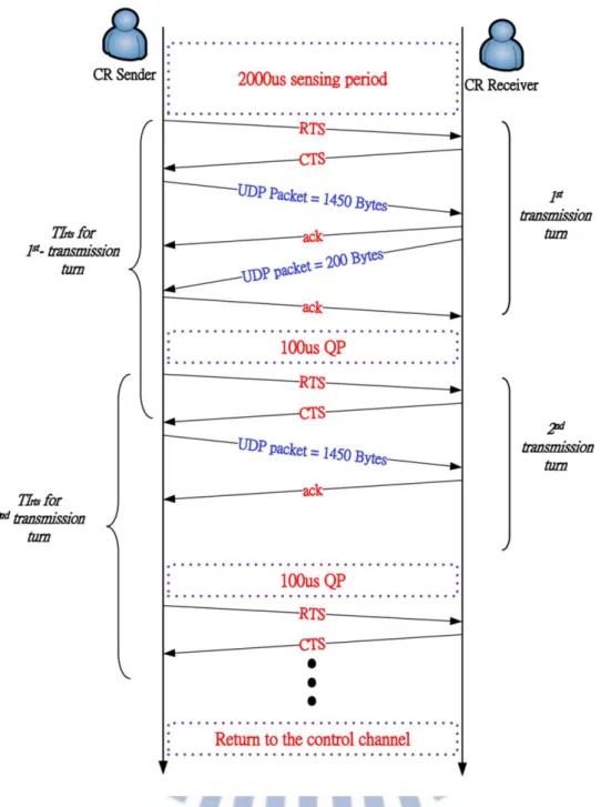
Figure 3.11 illustrates the negative impact to PUs QoS which is caused by the fixed TI setting in Bi-MAC when two-way bandwidth reservation is considered. In this case, the size
Figure 3.10 Illustration of Message Exchanges on Data Channel of Bi-MAC with Bi-directional Bandwidth Reservation when TXOPCR = 3
34
of data frames in CR sender’s queue is 1,450 bytes. On the other hand, the there is only one 200 bytes long data frame in CR receiver’s queue. The transmission run perform two-way bandwidth reservation due to the non-emptiness of CR receiver’s HOQ. With the design of Bi-MAC, TI is set to a duration which is long enough for transmitting two 1,450 bytes long data frames and two 802.11 ACK frames.
One can see in Figure 3.11, the first TI set to the RTS is longer than the actual transmission time of the first data transmission round due to the small packet of CR receiver. This inappropriate design strongly breaks the opportunity of PUs to claim the channel. The CRU pair entered the QP right after the ACK reply to CR receiver is transmitted. However, due to the RTS transmitted at the beginning of data transmission round, all neighboring PUs will set their Network Allocation Vector (NAV) according to TI of RTS. The NAV is an indicator for a station on how long it must defer from accessing the medium. In this case, the neighboring PUs receives the RTS will defer until the bandwidth reservation time of CRUs is finished. As a result, the CRU pair enter QP in the reserved time which PUs cannot send a RTS to claim the channel due to NAV. After QP, CRU starts the second data transmission round and transmits RTS again. The neighboring PUs overhear the RTS and set their NAV according to TI again. At this moment, one can see the reserved time of CRU pair of first transmission run is not finish yet due to the small size frame of CR receiver. The reserved time of CRU pair of second transmission round overlaps with the first one that gives no free time for PUs to claim the channel in between the first data transmission round and second transmission round. The same case happens when the CR receiver is running out of frames in its queue, as shown in the CR receiver’s second transmission round in the figure. In this case, both the CRUs enter the QP after the timers expire but the PUs are still deferring from accessing the medium due to the NAV.
35
The CRU pair elaborated above do enter the QP after every transmission round. However, the result is it does not protect the PUs’ right to claim the channel at all. In other word, the QP is totally a waste of time. Furthermore, the CRU pair occupy the data channel until the end of
Figure 3.11 Illustration of inappropriate TI setting of Bi-MAC with Bi-directional Bandwidth Reservation
36
the TXOPCRth data transmission round. This does not satisfy the spirit of cognitive radio: the
CRU should not interferes the right of primary users.
The design of Advance-Bi-direction CR MAC protocol (ABi-MAC)
To solve the above two problems, the authors of [4] propose ABi-MAC with two phases as follow:
Dynamic Bandwidth Allocation (DBA)
The main purpose of DBA is to determine the available transmitting frame number for both CR sender/receiver right after the BNP. Thus, the CRU pair can use the channel in a more efficient way to transmit the data frames on data channel. Through this purpose, the authors defined several new variations of TXOP:
MAX_PACKET: a pre-defined parameter. The maximum number of frames that CRU pair can transmit on the data channel. We use TXOPCR instate in this paper
BDs: the bandwidth demand of CR sender. It is a 5-bit field at the end of RTSCR
control frame. Representing the bandwidth demand from 0~31 data frames.
BDr: the bandwidth demand of CR receiver. It is a 5-bit field at the end of CTSCR
control frame. Representing the bandwidth demand from 0~31 data frames
Both BDs and BDr are decided dynamically through the BNP. In ABi-MAC, BDs and BDr
is carried in the RTSCR and CTSCR control packet separately. The Reservation Type (RT) in
37
The DBA of ABi-MAC operates in the following way. Firstly, assume that a CR sender maintains a separate queue for every CR receiver. Before sending an RTSCR, the CR sender
gets the number of data frames to be transmitted to a specified CR receiver by retrieving the current size of the corresponding queue. This information is treated as the value of BDs in the
RTSCR and shall be set using the following equation:
(3-3)
where Qs denotes the current queue size of the CR sender (for the specified CR receiver) and
M denotes the pre-defined and fixed network parameter TXOPCR. Upon receiving the RTSCR,
the CR receiver checks the corresponding queue that contains packets to be sent to the CR sender and then decides the value of BDr using Eq. (3-4). At the same time, the CR receiver
also records the value of BDs as the number of packets to be received from the sender (NPRs)
using Eq. (3-5). After that, it replies a CTSCR to the CR sender.
(3-4) Figure 3.12 Frame Format of the control packet RTSCR of ABi-MAC
38
where Qr denotes the size of the queue containing packets to be sent to the CR sender and A
denotes M/2.
(3-5) Finally, the CR sender reads the value of BDr in CTSCR and records the number of packets
to be received from the receiver (NPRr) using Eq. (3-6). It then finalizes its value of BDs using
the Eq. (3-7) where BDSF denotes the finalized value of BDs at the end of the BNP.
(3-6)
(3-7)
Using the proposed DBA, the ABi-MAC can offer very high flexibility in allocating bandwidth to the CRU pair regardless of their traffic condition. Through maintaining the BDs,
BDr, NPRs and NPRr, ABi-MAC can support (1) a uni-directional traffic flow from the CR
sender to the CR receiver, (2) a bi-directional traffic flow where both the CRU sender and the CR receiver have the same number of packets to send in their queues, and (3) a bi-directional traffic flow where the CRU sender and the CR receiver have unequal numbers of packets to send in their queues. In case (3), the CRU pair will swap their sender/receiver identities on the data channel when the CR sender has transmitted all packets in its queue but the CR receiver still has packets to send in its queue. At this moment, the bi-directional traffic flow temporarily degenerates to a uni-directional traffic flow.
Smart Transaction Interval Setting (STIS)
In phase two of the ABi-MAC, we proposed STIS such that the TI to be carried in the control packets can provide the neighboring PUs with the correct timing information when bi-directional bandwidth reservation is needed. In a typical 802.11 network, a two-way handshake of RTS/CTS is adopted for bandwidth reservation. In the process of handshaking,
39
the TI is carried in the RTS packet to indicate how long a sender wants to hold the medium. In return, the receiver replies with a CTS packet echoing the expected duration of transmission. Through the exchange of RTS and CTS control packets, all the nodes within the hearing distance of either the sender or receiver or both will set their Network Allocation Vector (NAV) according to the TI in the overheard packets.
In the presence of bi-directional traffic flow, we further proposed a conditional transmission of RTSe by the CR sender after receiving a CTS. As a result, the CR sender can
effectively update all of its neighboring PUs with its latest TI whenever bi-directional bandwidth reservation is required. The format of RTS e in ABi-MAC is identical to that of the RTS packet. In the STIS, the TI of a CTS packet is set according to the following equation:
(3-8) (3-9) where Dcts , Drtse , Ddata , and Dack refers to the transmission time of a CTS, RTSe , data, and
ACK packet, respectively. Upon receiving a CTS packet, if a bi-directional bandwidth reservation is anticipated, the CR sender immediately transmits an RTSe control packet with
the TIrtse calculated based on Eq. (3-9).
In summary, the proposed ABi-MAC can reserve bandwidth dynamically to further utilize the spectrum holes of the authorized bandwidth. In addition, the ABi-MAC can support asymmetric two-way traffic flows with variable packet sizes. Simulation results show that our proposed ABi-MAC can significantly enhance the aggregate throughputs of CRUs in a CRN and dramatically improve the spectrum efficiency without degrading the performance of PUs.
40
Chapter 4 Motivation
The related work in chapter 3 all focus on the same target: a CR MAC protocol over IEEE 802.11 network. Those works do make a significant contribution for CRN. However, the verification or simulation in [1], [2], [3], and [4] seems unable to satisfy the real world situation with the fast growing technology. In those works, they use IEEE 802.11b stations to be PUs that is barely used in these days. And the data rate applied in the verification and simulation for both PUs and CRUs is 2 Mbps that is also an unusual choice in real world. The new versions IEEE 802.11a/g/n are now widely used in the real world and the supported data rate of IEEE 802.11a/g is up to 54 Mbps. The IEEE 802.11n even supports a 150 Mbps high data rate with only one single antenna [8]. We think those work should be examined and verified under the conditions of using higher data rate and using a more advance version of IEEE 802.11 stations to be PUs.
Furthermore, we consider an improvement to enhance the efficiency of CR-MAC protocol through frame aggregation mechanism which is proposed in IEEE 802.11n [8]. Since, physical level data rate improvements do not increase user level throughput beyond a point because of 802.11 protocol overheads, like the contention process, inter frame spacing, physical level headers (Preamble + PLCP)and acknowledgment frames. The same problems should happen in CR MAC protocol and could be more serious due to other protection concern for PUs like channel sensing and QP overhead. The frame aggregation mechanism is proved that it does improve the efficiency of IEEE 802.11 (since IEEE 802.11n is widely used in the real world). We can expect that frame aggregation mechanism could also enhance the
41
efficiency of CR MAC protocol. However, the CR MAC protocol has to consider the protection of PUs additionally. In the following chapter, we will implement the frame aggregation mechanism on both Uni-MAC and ABi-MAC to increase the available throughput and analysis the effect from the enhancement to PUs.

![Figure 2.1 Normalized overhead under different data rate and payload in [5] Y. Xiao,](https://thumb-ap.123doks.com/thumbv2/9libinfo/8243876.171439/17.892.139.791.326.923/figure-normalized-overhead-different-data-rate-payload-xiao.webp)
![Figure 2.2 The Maximum Throughput and the Throughput Upper Limit for IEEE 802.11a in [5] Y](https://thumb-ap.123doks.com/thumbv2/9libinfo/8243876.171439/18.892.135.791.122.900/figure-maximum-throughput-throughput-upper-limit-ieee-y.webp)