雙向環形光網路中
具最大使用效率及最少停留點的機制
研究生 : 林正昕 指導教授 : 張仲儒教授
國立交通大學電信工程學系碩士班
中文摘要
近幾年來,由於分波多工(WDM)技術的出現,在廣區域網路(WAN)中能獲得的傳 輸頻寬也大量的增加(如: 2.5, 10, 40Gps)。隨著時間經過,光纖網路的發展不但有了 很大的進步,而且訊務的流量也大幅激增。一個訊務可能被分配使用一整條波長的頻寬 去傳輸,然而,相對一個波長的頻寬,一個訊務的流量然是相當的小。為了有效的利用 資源,利用訊務彙集的技術,把許多需求頻寬小的訊務彙集到頻寬大的波長上是很重要 的研究議題。 在本篇論文中,我們討論了多重傳播動態訊務路徑選擇及彙集的問題,我們的目標 是要讓波長頻寬的使用效率達到最高且同時降低連線呼叫的拒絕率,我們把這個問題公 式化成整數線性規劃(ILP)。為了解決這個問題,我們提出了具最大利用效率及最少停留 點(MUMO)的機制。在 MUMO 的機制中有兩個主要的步驟 :決定多重傳播訊務的最少 停留點路徑以及讓使用度最大的多重傳播訊務彙集。從模擬結果我們可以知道不論在何 種環境,MUMO 機制的表現都比其他機制的表現好很多,我們也驗證了 MUMO 機制能 很有效的安排多重傳播訊務,因此MUMO 機制是一個具可行性且十分吸引人的方法。A Maximum Utilization and Minimum Hops Scheme
for Bidirectional Optical Ring Networks
Student: Zheng-Xin Lin Advisor: Dr. Chung-Ju Chang
Department of Communication Engineering
National Chiao Tung University
Abstract
In recent years, the emergency of wavelength division multiplexer (WDM) has led to a
tremendous increase in the available transmission capacity (e.g. 2.5, 10 and 40Gbps) for wide area networks (WAN). The progress of optical network evolves with time; meanwhile, the carried traffic streams surge. The required bandwidth of the traffic stream is usually much smaller than the capacity of a wavelength. Thus, many lower-speed traffic streams should be multiplexed onto a high-speed wavelength channel by traffic-grooming techniques
In the thesis, a traffic routing and grooming problem, which the traffic is dynamic, multicast and nonuniform in bi-directional optical ring networks, is studied. We propose a maximum utilization and minimum hops (MUMO) scheme with an objective to reduce the new call blocking probability and to maximize the utilization of used wavelength.
There are two main operations in the MUMO scheme: multicast traffic routing with minimum hops and multicast traffic grooming with maximum utilization. The main purpose of the operations is to achieve better system utilization without changing the lightpath topology. From the simulation results, the performance of the MUMO scheme is much better than the performance of the other conventional schemes no matter in which environment. Consequently, we can conclude that the MUMO scheme is a feasible and attractive scheme for optical bi-directional ring network.
誌謝
兩年的碩士生活不知不覺中就結束了,心中感覺十分複雜,兩年的碩士生活中充滿 著許多不同的回憶,在過程當中獲得了許多,從一開始的全然無知,到今天可以完成這 一本碩士論文,能夠完成這篇論文,要感謝許許多多的人,首先必須感謝張仲儒教授對 我的指導及教誨,引導我論文正確的研究方向,除此之外還教導我做人處世的道理,再 來要感謝立峰學長在忙碌之中還是不厭其煩的替我解答,接著感謝芳慶學長再工研院來 回奔波每次都給予我精準又扼要的建議,另外要感謝詠翰、志明、文祥、耀興學長在我 面對困難的時候,大方的慷慨解囊,然後要感謝琴雅、煖玉、家源、俊帆,再我還是一 年級的時候帶我快速的融入701 這個大家庭,度過豐富的碩一生活。謝謝帶給我很多歡 樂還有打氣的學弟妹,巧瑩、維謙、邱胤、英奇、浩翔、宗利、尚樺,當然還很感謝在 這兩年中陪我一起成長,一起修課,一起打鬧的建安、建興、佳泓、佳璇、世宏,我們 一路互相扶持,一起討論問題,一起打球,一起煩惱,一起創造許多難以忘懷的回憶。 最後我要感謝我的父母及親人對我的照顧以及支持,讓我沒有後顧之憂,盡情的追 逐我的夢想,你們的支持給我很大的鼓勵,當然也感謝從大學以來一直支持關心我的女 友,岱琪。我願將這篇碩士論文獻給所有幫過我,愛護我的人,一起分享這份喜悅。Contents
中文摘要
... i
Abstract ... ii
Contents... iv
List of Figures ... v
List of Tables ... vi
Chapter 1 Introduction ... 1
Chapter 2 System Model... 6
2.1 Network Architecture... 6
2.2 Node Function and Operations ... 7
2.3 Source Model... 10
2.4 Notation and Definition... 11
Chapter 3 Problem Statement ... 14
Chapter 4 Maximum Utilization and Minimum Hops Scheme ... 18
4.1. Multicast Traffic Routing With Minimum Hops ... 19
4.2 Multicast Traffic Grooming With Maximum Utilization... 24
Chapter 5 Simulation Result ... 31
Chapter 6 Conclusion... 46
List of Figures
Figure 2.1 Bi-directional metro-Access Rings...7
Figure 2.2 Node architecture...8
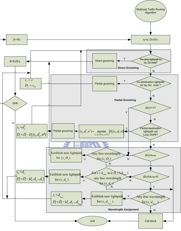
Figure 4.1 Flowchart of multicast routing algorithm...23
Figure 4.2 Flowchart of multicast traffic grooming algorithm...30
Figure 5.1 The blocking probability of versus traffic loads...33
Figure 5.2 The utilization of used wavelength versus traffic loads...33
Figure 5.3 The blocking probability versus multicast ratio...34
Figure 5.4 The utilization of used wavelength versus multicast ratio...35
Figure 5.5 The blocking probability versus number of max destinations...36
Figure 5.6 The utilization of used wavelength versus max number of destinations...37
Figure 5.7 The blocking probability with different mean service rate...39
Figure 5.8 The utilization of used wavelength with different mean service rate...39
Figure 5.9 The blocking probability in different number of network nodes...40
Figure 5.10 The utilization of used wavelength in different number of network nodes...41
Figure 5.11 The blocking probability with different probability of the type of new request...42
Figure 5.12 The utilization of used wavelength with different probability of the type of new request...42
Figure 5.13 The blocking probability with differentkmax...44
List of Tables
Table 2.1: Notation of parameter in mathematical formulation……….………..12 Table 2.2: Notation of the sets in mathematical formulation……….………..13 Table 2.3: Definition and Notation of the variable for mathematical formulation……….….….13
Chapter 1 Introduction
Chapter 1
Introduction
he wavelength-division multiplexer (WDM) has led to a tremendous increase in the available transmission capacity (e.g. 2.5, 10 and 40Gbps) for wide area networks (WAN). A traffic stream could be assigned to use one whole wavelength. However, the required bandwidth of the traffic stream is usually much smaller than the capacity of a wavelength, and the available wavelengths are limited. Thus, many lower-speed traffic streams should be multiplexed onto a high-speed wavelength channel by traffic grooming to efficiently utilize the network resources. The number of low-rate traffic requests multiplexed in a wavelength channel is called the grooming factor. For example, if the bandwidth of a wavelength channel is OC-48 (i.e.2.488Gbit/s) and the base bandwidth of a connection is OC-12 (i.e.0.622Gbit/s), then four connections can be groomed and supported by one OC-48 channel. In this case, the grooming factor is four. The problem of traffic grooming becomes increasingly important for emerging network technologies. An overview of the traffic grooming technique and survey of some typical works was reported in [1], [2].
T
In the design of traffic grooming, it can be classified into various categories, according to the network configuration, traffic and cost function. For the topology of networks, it can be categorized into ring or mesh. A ring network can also be a unidirectional ring or
bidirectional ring. For the traffic characteristics, according to the bandwidth request, it can be uniform or non-uniform. The bandwidth request of each user is the same, called uniform traffic; otherwise, the traffic is nonuniform. And, according to the system connection it also can be classified into dynamic traffic or static traffic. Static traffic means the traffic streams are set up all at once and fixed thereafter. Dynamic traffic means that traffic streams are set up and terminated at arbitrary time. For the objective cost function, traffic grooming may categorize into five types. The first one is the minimization of the number of Line Terminating Equipment (LTE). The second one is the reduction of the cost of actual electronic processing involved in Optical-Electric-Optical (O/E/O). The third one is to minimize the maximum number of lightpaths originating/terminating at a network node. The fourth one is the maximization of traffic throughput of the optical network. The last one is the minimization of blocking probability of new call request in dynamic traffic. Also, the traffic grooming can be classified into three categories: unicast (point-to-point), multicast (point-to-multipoint) and groupcast (multipoint-to-multipoint).
Many researches on traffic grooming in WDM networks have exclusively dealt with unicast traffic [3] - [8]. Static traffic was considered in the [3]-[6]. In [3] and [4], the authors considered uniform traffic in general topology network. The objective of the two papers is to minimize wavelength usage in the network. The authors formulated the problem into an integer linear program and proposed a simple approach to find a suboptimal solution. Non-uniform traffic in WDM ring was studied in [5] and [6]. In [5], the objective is to minimize total amount of electronic switching at all network nodes. The authors presented a new framework of bound which can be used to evaluate the performance heuristic. They gave both upper and lower bound which required less computation than the optimal solution.
In [6], both uni- and bi-direction ring were considered. The object of this paper was reducing both the number of wavelength and the number of LTE. Some lower bounds in
the number of wavelength and LTE required for a given traffic pattern were also derived. The heuristic proposed in this paper can be considered in two phases. The first one is the circle formulation. Each circle consists of multiple non-overlapping connections. After the circles were constructed, optimal or near-optimal algorithms were used to groom circles onto a wavelength.
In [7] and [8], dynamic non-uniform traffic was considered in ring. In [7], a special topology of interconnected ring was considered, and the GA approach was used to find a topology with minimum number of ADMs to support a set of traffic matrices. Unlike the dynamic problem in [7], a dynamic provisions and grooming problem was considered in [8]. This kind of dynamic problem is measured by arrival time and holding time. The objective was to minimize the blocking probability.
Multicast is a kind of group communication, which requires simultaneous transmission of messages from a source to a group of destinations. It is expected that a sizable portion of the traffic in future high performance networks will be multicast, for example, multi-party conferencing, video distribution, network news distribution, and web content distribution to proxies. However, most multicast service applications require only sub wavelength capacity (for example, HDTV needs only 20Mbps). It would be inefficient to assign a whole lightpath to each lower-rate multicast streams. So the problem of multicast traffic grooming over optical networks has received significant attention [2].
Some multicast problems have been investigated in [9] - [13].A mesh network and the dynamic multicast traffic grooming were considered in [9] - [11]. The objective cost function is to minimize the loss probability. In [9], two simple approaches were proposed to groom dynamic traffic. The first approach is the single-hop (SH) traffic grooming. A new call has the same source and destination(s) with a working lightpath (or light tree) and the lightpath has enough bandwidth to support the new call, then, the new call will be groomed with the lightpath. The second approach is the multi-hop (MH) traffic grooming.
In MH, a lightpath (or light-tree) that has the same destination(s) with enough bandwidth which called “to destinations light-tree” (TDLT) was searched. After such a lightpath is found, another lightpath between the source of the new call and the source of TDLT by SH approach was selected. Note that only grooming by the SH, the traffic can be transmitted all-optically before reaching the destination(s).
An approach called hybrid provisioning grooming scheme was proposed in [10]. This approach improves the MH by combining the provision and un-provisioned lightpath and light-tree to serve a new connection. In MH, when a lightpath cannot be found between the source of a new call and the source of TDLT, the new call will be blocked. In this approach, the source would know if there is a TDLT to its destination(s). If enough resource was found, a new lightpath would be set up. In [11], the authors proposed multicast tree decomposition to improve the approaches used in [10]. The authors first divided a new multicast tree into many subtrees with one or two destination. Then, they tried to find multicast trees that have the same destinations with those subtree from current tree and groom them.
A ring topology with multicast static traffic was investigated in [12] and [13]. In [12], the authors considered single-source multicast traffic and the object is to minimize the number of LTE. An approximate algorithm was proposed by transforming the grooming problem into a weighted set cover problem. A bi-directional ring and uniform traffic was considered in [13]. The objective of this paper is to minimize the number of LTE. The authors proposed two heuristic algorithms. One is to use the minimum spanning tree routing and transform each multicast session to a set of unicast, and then, it uses the approach proposed in [6] to construct circles and groom circles. The other is to do the routing and circles construction simultaneously. The latter is effective than the former.
Ring networks have been studied in many researches. Most of them focus on unicast and static. Few dynamic and non-uniform multicast traffic researches ware considered in
ring network. Therefore, we are motivated to study the traffic grooming problem in optical bidirectional ring network with dynamic non-uniform multicast traffic. We propose the node architecture which is equipped in ring network and have the ability of traffic grooming and light splitting. Their object is to reduce the new call blocking probability and maximize the utilization of used wavelength.
The integer linear problem for the traffic grooming problem is formulated in mathematical form. However, the optimal solution by the ILP is infeasible due to the computation complexity. We propose a suboptimal multicast traffic grooming scheme, called Maximum Utilization and Minimum Hops (MUMO) scheme. Two main operations in MUMO: traffic routing and traffic grooming. In traffic routing, we propose a scheme which chooses the route with minimum hops for bidirectional ring and we choose the route according to the remained capacity in each fiber. So the routing scheme can save more resource for future calls. In the traffic grooming, we utilize the features of ring network and multicast traffic to effectively grooming the new call. The multicast traffic grooming scheme increases the probability of finding lightpath to groom and increases the utilization. Because of the two operations, MUMO can achieve the better utilization without changing the lightpath topology and reduce the blocking probability.
Chapter 2 System Model
Chapter 2
System Model
n this section, the basic environment, includes the network architecture and the node architecture/function, is described. In addition, the operations of the network and the source model about traffic also described here.
I
2.1 Network Architecture
As shown in Fig. 2.1, the network topology considered is a WDM metro ring architecture, which consists of N nodes, labeled as 1, 2, …, N counterclockwise. Each node provides several passive optical networks (PONs) with tree topology to building users (BUs). There is a pair of fibers between node
i
and nodei
+1, 1≤i
≤N-1, and also between node N and node 1, one carrying traffic stream in counterclockwise direction and the other one carrying traffic stream in clockwise direction, in addition, each fiber contains W wavelengths,. The fiber link from nodei
to nodei
+1 is labeled asi
ccw and that fromnode
i
+1 to nodei
is labeled asi
cw. So the links of the network are labeled as 1ccw, 2 ccw, …, N ccw counterclockwise and 1cw,2cw, …, N cw clockwise. About the PON, we adopt one wavelength to carry traffic streams from the node to BUs and another wavelength to carry traffic streams from BUs to the node.
Figure 2.1 Bi-directional metro-Access Rings
2.2 Node Function and Operations
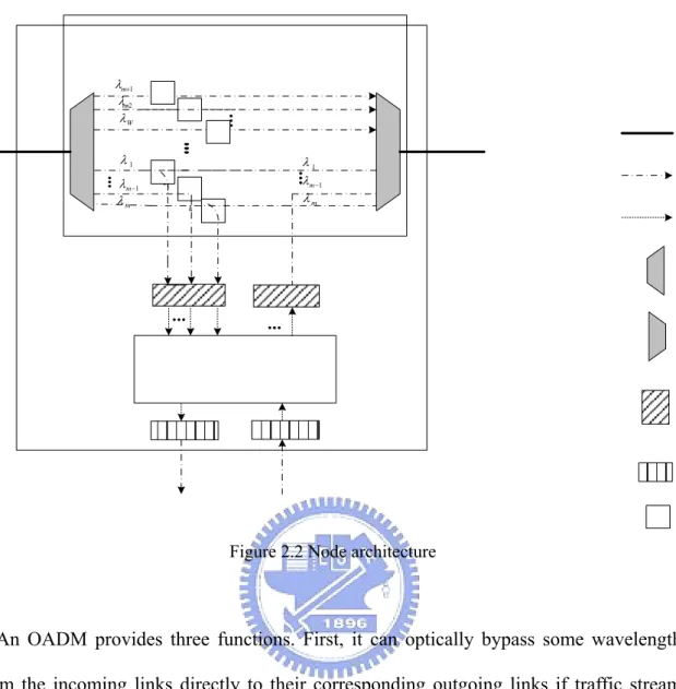
Each node in the metro access ring is equipped with an optical add-drop multiplexer (OADM), an optical line terminal (OLT), W tunable transmitter/receiver pairs, and a fixed transmitter/receiver pair, as shown in Fig. 2.2 A tunable transmitter (receiver) processes the capability of transmitting (receiving) any of W wavelengths, respectively. Conversely, a fixed transmitter and receiver process the capability of transmitting and receiving a fixed wavelength, respectively. The tunable and fixed transmitter executes electrical-to-optical conversion, while the receivers execute optical-to-electrical conversion. A multiplexer aggregates wavelengths into a single fiber, while a de-multiplexer dispatches wavelengths from the fiber. Additionally, the OADM chooses the wavelength whose traffic streams are required to be dropped out of the node. As Fig.2.2 shown, we can see that there are W wavelengths which are passed or dropped at this node.
1 λ 1 m λ − m λ 1 m λ+ 2 m λ+ W λ m λ 1 λ 1 m λ−
Figure 2.2 Node architecture
An OADM provides three functions. First, it can optically bypass some wavelengths from the incoming links directly to their corresponding outgoing links if traffic streams carried in these wavelengths are not necessary to be dropped at this node. Secondly, it can optically drop some wavelengths from the incoming links to the tunable receivers and then the tunable receivers convert the traffic streams carried by the wavelengths into electronic form. Thirdly, a splitter is imposed on an OADM, so it also has the capability of tapping a small amount of optical power from a wavelength to a tunable receiver and forwarding the rest to its corresponding out-going link. The small amount of optical power will be converted into electronic form and then the node can receive the traffic stream on the wavelength. The capability is termed as drop-and–continue (DaC) which can support multicast effectively. Finally, the OADM can also multiplex some wavelengths to the outgoing links.
An OLT perform five functions which are operated in electrical domain. First, it can groom multiple low-speed streams originating from BUs to a high-speed stream, and then transmit the high speed traffic stream to the tunable transmitter. Secondly, it can extract some low-speed streams out of a high-speed stream. Thirdly, it can make a copy of the traffic stream that is received from the tunable receiver. Fourthly, it has the capability of reconstructing and amplifying the electric traffic stream. Finally, it can transmit the low-speed traffic streams terminating at the node to the BUs by a fixed transmitter and also receive the traffic streams originating from the BUs by a fixed receiver.
When the wavelengths carrying traffic streams come across the node, the node will execute one of the following operational procedures which depend on the transmission conditions.
1. If the node is the final destination of the traffic streams, the OADM drops wavelengths to a tunable receiver. A final destination of a traffic stream means that the traffic stream would not need to forward to any node after this destination node. The tunable receiver would transform data streams from the optical into electrical domain and then send them to the OLT. The OLT would extract the traffic streams from the high-speed traffic streams and send them to the fixed receiver. This process is called “drop-only”.
2. If the node is a destination (but not a final destination) of the traffic streams and the optical power of the wavelength is enough, the splitter in the OADM may tap a small amount of optical power from a wavelength channel for using by the local node while forwarding the remained part on that wavelength channel to the output. This process is called “drop-and-continue”.
3. If the node is a destination (but not a final destination) of the traffic streams and the optical power of the wavelength is not enough, OADM would drop the wavelength to a tunable receiver. The tunable receiver would transform data
streams from the optical into electrical domain and then send them to the OLT. The OLT would extract the traffic streams and then amplify and reconstruct the electric traffic signal. After regeneration, total traffic stream is duplicated; one is sent to the fixed transmitter and the other one is converted to optical domain and forwarded to the output.
4. If the node is not a destination of the traffic stream, the OADM optically pass the traffic stream through the node. This process is called “continue-only”.
5. If the traffic streams from the BUs would want to go to the other nodes, they are sent to the OLT and the OLT would groom all the traffic streams and send them to the tunable transmitter.
In addition, it is assumed that each node has the information of total traffic streams in each wavelength, and every element in each node is coordinated by out-of band control signals. According to the information, the procedure of traffic grooming can be executed by the OLT at each node.
2.3 Source Model
In this paper, the traffic model which we consider is a dynamic and non-uniform multicast traffic; that is, the number of connections in the ring changes with time and the bandwidth requests from various users may be different. We assume the capacity of a wavelength is OC-48. The bandwidth request of a new call is OC-R, where R is one of the following numbers: 1, 3, 12 and 16. The probability of the type of a new call is assumed to be p , wherer r=1, 2, 3, 4, and 4 1 1 r r p = =
∑
. In addition, we assume that each of the N nodes was given equal probability to be the source node for the new call and we assume that the probability of multicast traffic is p . The size n of a multicast destination set D was mof the destination set n was determined, the nodes in the destination set were then chosen such that every subset of n of the N nodes was equally probability to be the destination set. This is done by the following processes. The first node is chosen from the N-1 nodes with equal probability. Then, second node is also chosen from the remaining N-2 nodes with equal probability. This process would be continued until all the n nodes in the destination set were chosen. The arrival process of the new call requests is assumed to be a Poisson process with mean arrival rate λ (calls/sec). A new traffic stream of type r is with probability p , and its service time is exponential distribution with mean service time r 1/μm (sec). As a result of our traffic model, the traffic streams will arrival one by one and the arrival time of the next new call is not known in advance.
Note that we will assume that the source of a request has the capability of transmitting multiple duplicate traffic streams in clockwise and counterclockwise directions with different wavelengths. So the source of a multicast call can transmit both clockwise and counterclockwise to its destinations simultaneously and the source of a unicast call can choose one of the two directions to transmit according to its routing.
2.4 Notation and Definition
In this section, we will give some notations and definitions in the network that we will use. A fiber link is a physical link between two adjacent nodes. In the network, there are two fibers between any two adjacent nodes; one for each direction. A lightpath is an optical channel, where traffic is switched optical at intermediate nodes. A lightpath may consist of multiple fiber links and would occupy the same wavelength on all fiber links through which it passes. Note that when the traffic stream on a wavelength passes a node with the procedure “drop-and-continue”, it is still on the same lightpath since the traffic stream still bypasses the node optically with only tapping some power of the light.
Moreover, we assume the wavelength must be dropped and then convert the traffic to electric domain after processing “drop-and-continue” kmax-1 times. It means that there are
at most kmax destinations on a lightpath. We make this assumption because the power of
light must be considered. When the traffic stream passes a node with “drop-and-continue”, the power of light will decrease to half of origin. In order to be practical, we make this assumption in the system mode. We also assume that multiple lightpaths with the same originating node and terminating node are allowed. A connection request includes multiple lightpaths from the source to the destinations of a multicast call.
Table 2.1, 2.2 and 2.3 represent the notations and the definitions we used. Note that the following tables only show the notations for counterclockwise direction. The notations for clockwise are represented by replacing ccw with cw on the subscript of that for counterclockwise (i.e. lccw and lcw). For simplicity, we only show the notations for
counterclockwise in the following table.
Notation Definition
N The number of nodes in the network
W The number of wavelength per fiber. We assume all the fibers in the network
have the same number of wavelength.
C The capacity of each wavelength.
(i, j, w) ccw A lightpath which traverse from node i to node j on wavelength w in
counterclockwise direction without optical-electric conversion. i, j V ,
and 1 .
∈
i≠ j ≤ ≤w W
(s, D) A multicast (unicast) call with source s and destination set D= {d1, d2, …, dn}
where d1, d2…dn are the n destination nodes of the multicast call (in
counterclockwise order). The multicast (unicast) call may traverse through a single or multiple lightpaths. s∉D
The required transmission capacity OC-R of a call. R R∈{1, 3, 12, 16}.
R
Maximum number of destinations on a lightpath (the destinations do not include the originating node of the lightpath)
max
k
Table 2.1: Notation of parameter in mathematical formulation
Notation Definition
L(i, j) ccw A set that consists of all the lightpaths that originate at node i and terminate
at node j in counterclockwise direction. L(i, j)={ (i, j, w)1 w W≤ ≤ }
Fccw A set tat consists of all fiber link in counterclockwise
Lightpath set consists of successively non-overlapping lightpaths which form a complete path from node s to node . Each lightpath in the set can’t use the same fiber link.
i
d ( , )i ccw
C s d
( , )s D
R The routing complete path for (s,D) R( , )s d ∈ Ω( , )sD where Ω( , )s D is the
set contains all kind of spanning tree for (s,D).
Table 2.2: Notation of the sets in mathematical formulation
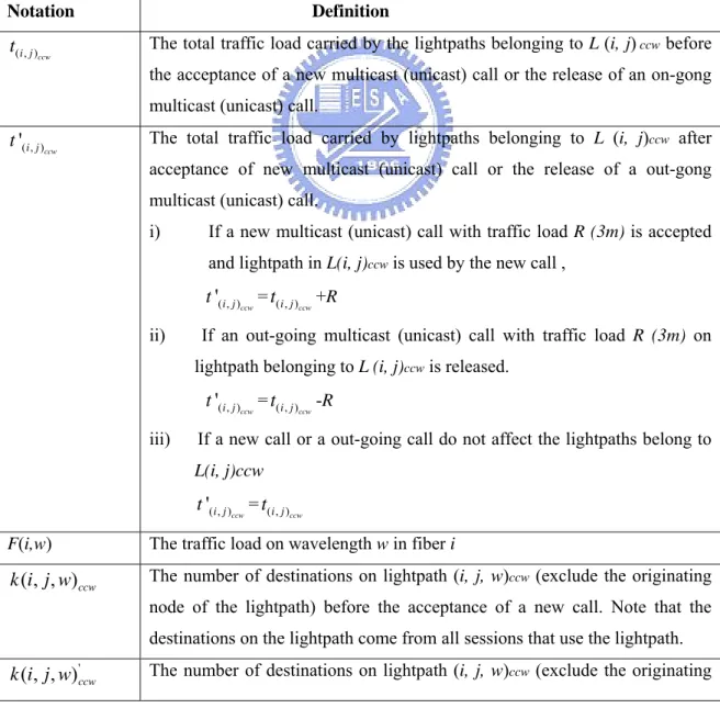
Notation Definition
The total traffic load carried by the lightpaths belonging to L (i, j) ccw before
the acceptance of a new multicast (unicast) call or the release of an on-gong multicast (unicast) call.
( , )i jccw t
The total traffic load carried by lightpaths belonging to L (i, j)ccw after
acceptance of new multicast (unicast) call or the release of a out-gong multicast (unicast) call.
( , )
'
ccw
i j t
i) If a new multicast (unicast) call with traffic load R (3m) is accepted and lightpath in L(i, j)ccw is used by the new call ,
'( , ) = +R
ccw
i j
t t( , )i jccw
ii) If an out-going multicast (unicast) call with traffic load R (3m) on lightpath belonging to L (i, j)ccw is released.
'( , ) = -R
ccw
i j
t t( , )i jccw
iii) If a new call or a out-going call do not affect the lightpaths belong to
L(i, j)ccw '( , ) = ccw i j t ( , ) ccw i j t
F(i,w) The traffic load on wavelength w in fiber i
The number of destinations on lightpath (i, j, w)ccw (exclude the originating
node of the lightpath) before the acceptance of a new call. Note that the destinations on the lightpath come from all sessions that use the lightpath.
( , , )ccw
k i j w
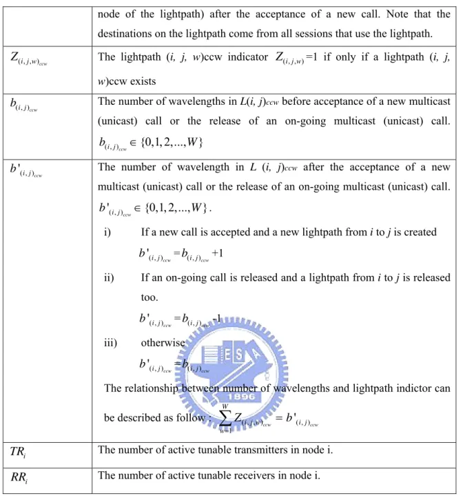
'
( , , )ccw
node of the lightpath) after the acceptance of a new call. Note that the destinations on the lightpath come from all sessions that use the lightpath.
( , , )i j wccw
Z The lightpath (i, j, w)ccw indicator =1 if only if a lightpath (i, j,
w)ccw exists
( , , )i j w
Z
The number of wavelengths in L(i, j)ccw before acceptance of a new multicast
(unicast) call or the release of an on-going multicast (unicast) call.
( , )i jccw {0,1, 2,..., } b ∈ W
( , )i jccw b
The number of wavelength in L (i, j)ccw after the acceptance of a new
multicast (unicast) call or the release of an on-going multicast (unicast) call. . ( , ) ' {0,1, 2,..., } ccw i j b ∈ W ( , ) ' ccw i j b
i) If a new call is accepted and a new lightpath from i to j is created '( , ) = +1 ccw i j b ( , ) ccw i j b
ii) If an on-going call is released and a lightpath from i to j is released too. '( , ) = -1 ccw i j b b( , )i jccw iii) otherwise '( , ) = ccw i j b b( , )i jccw
The relationship between number of wavelengths and lightpath indictor can be described as follow : ( , , ) 1 ccw W i j w w Z = =
∑
b'( , )i jccwThe number of active tunable transmitters in node i.
i
TR
The number of active tunable receivers in node i.
i
RR
Table 2.3: Definition and Notation of the variable for mathematical formulation
Chapter 3 Problem Statement
Chapter 3
Problem Statement
n this section we will state the dynamic multicast traffic grooming problem we want to solve. In fact, the dynamic multicast traffic grooming problem contains two main parts: traffic routing and traffic grooming. The traffic routing is to decide the route used to transmit a multicast (unicast) call from source to its all destination(s). The traffic grooming is to decide how to arrange the multicast (unicast) call into the network according to the route. We propose a grooming scheme can maximize utilization and a routing scheme can minimize used resource to solve the problem. Since the route of a new call can be decided by the routing scheme, the dynamic grooming problem can be represented in mathematical form according to the route we choose. The problem of dynamic multicast traffic grooming can be formulated as an integer linear programming (ILP) problem, where the design goal is to maximize the wavelength utilization in the network. It is expressed as
I
Maximize ( , ) ( , ) , 1 ( , ) ( , ) , 1 ' ' ' ' ccw cw ccw cw N i j i j i j i j N i j i j i j i j t t C b b = ≠ = ≠ ⎛ + ⎞ ⎜ ⎟ ⎜ ⎟ ⎜ ⎜ × ⎟ ⎜ ⎟ ⎝ ⎠∑
∑
( ) ( + ⎟ ) , (3.1)z Traffic constraint: ( , ) ( , ) ' ' ccw ccw i j i j t ≤b ×C,∀L i j( , )ccw, (3.2) '( , ) '( , ) , cw cw i j i j t ≤b ×C ∀L i j( , )cw, .(3.3) z Lightpath constraint: ( , ) ( , ) ( ) ' ccw ccw ccw i j L i j B l b W ∈ ≤
∑
,∀lccw, .(3.4) ( , ) ( , ) ( ) ' cw cw cw i j L i j B l b W ∈ ≤∑
,∀ , (3.5) lcwz Wavelength assignment constraint: ( , , ) , , ( , ) ( ) 1 ccw ccw ccw i j w L i j B l Z ∈ ≤
∑
∀lccw w, .(3.6) ( , , ) , , , .(3.7) ( , ) ( ) 1 cw cw cw i j w L i j B l Z ∈ ≤∑
∀lcw w z Transceiver constraints: '( , )i jcw i, , (3.8) j b ≤TR∑
∀ ∈j N ≤∑
∀ ∈i N ≤∑
j N ≤∑
i N ( , ) ' cw i j j i b RR , , .(3.9) ( , ) ' ccw i j i j b TR ,∀ ∈ , .(3.10) ( , ) ' ccw i j j i b RR ,∀ ∈ , (3.11) z Light power constraint:k i j w( , , ) 'ccw ≤kmax,∀i j w, , , .(3.12) max ( , , ) 'cw k i j w ≤k ,∀i j w, , , (3.13) z Routing constraint: C s d( , )i ccw∪C s d( , i+1)cw=R( , )s D ,d di, i+1∈{d d0, 1,...,dn}, (3.14)
the maximum capacity. The lightpath constraint indicates that the bound imposed by the total number of wavelengths. The wavelength assignment constraint expresses that a wavelength in the same fiber link can only be assigned to a lightpath. The transceiver constraint shows that the number of lightpath from node i to node j in one direction must be less than or equal to the number of transmitters and receivers. The light power constraint indicates a lightpath at most passes kmax− splitters. The routing constraint 1 expresses the traffic stream must be groomed according to the route. The lightpaths used by a multicast call forms complete lightpaths in counterclockwise and clockwise. The complete path in counterclockwise is used to transmit traffic from source to {d1,d2,…,di}
and the complete path in clockwise is used to transmit traffic from source to {di+1,di+2,…,dn}. di is decided by the route of the multicast call. The two complete
lightpaths form the routing complete path of the multicast call.
The ILP problem for the dynamic unicast traffic grooming is NP-complete [14]. Unicast is a special case of multicast when a multicast call has only one destination. So the ILP problem for the dynamic multicast traffic grooming is also NP-complete. Solving the ILP problem directly is not practical when the network size is large because of the complex computation. If the traffic mode is static, the computation time may be negligible. However, considering dynamic traffic model, computational complexity is important. So we propose a suboptimal scheme to solve the problem in the next chapter.
Chapter 4
Maximum Utilization and
Minimum Hops Scheme
Chapter 4 Maximum Utilization and Minimum Hops Scheme
he dynamic traffic-grooming problem can be seen as a static one from the snapshot view. When a new call arrived or a current call left, it could be considered as giving a new traffic matrix. However, the complex computation is needed to find the optimal solution for the new traffic matrix and many current calls are necessary to be rearranged. The optimal solution is impractical for dynamic model due to the long computation time. So a simple algorithm must be proposed to achieve the suboptimal solution. Some heuristic algorithms in the papers [10] and [11], which focused on the multicast dynamic traffic, have been proposed. However, these algorithms that proposed for mesh network are not suitable for the ring network and they don’t consider the problem of routing. We propose a new heuristic scheme, called Maximum Utilization and Minimum Hops (MUMO) scheme, to decide the route with minimum hops and maximize the utilization efficiency of wavelengths. The MUMO can reduce the number of blocked connections. The “MUMO” is divided into two main parts to solve the routing and grooming problems: (a) multicast traffic routing with minimum hops (b) multicast traffic grooming with maximum utilization. The two parts are described in the following.
4.1. Multicast Traffic Routing With Minimum Hops
We give a brief overview about the routing of multicast call in ring networks and propose an adaptive routing scheme. In order to explain the routing of multicast call, we first give a simple example. Considering a bi-directional ring of 10 nodes (labeled as 1, 2,…,10 counterclockwise)and a multicast call with source 1 and destination set {4, 7}. The route of the new call may be one of the following 3 possible routes.
1. The traffic is transmitted from 1 to {4, 7} by counterclockwise fiber links 2. The traffic is transmitted from 1 to {4, 7} by clockwise fiber links
3. The traffic is transmitted from 1 to 4 by counterclockwise fiber links and from 1 to 7 by clockwise fiber links.
Each route that is listed above can be represented by the absence of an arc between any two nodes in the set {1, 4, 7}. The first route can be represented by the absence of the arc between 7 and 1. Similarly, the second route can be represented by the absence of the arc between 1 and 4. The absence of the arc between 4 and 7 represents the 3rd route.
In general case, we consider a new call with source s and destination set D={d1,d2,…,dn}
(in counterclockwise order) arrivals a ring. The ring would be divided into { }s ∪D =n+1 arcs by the source and the destinations. Let d0=s and Arc(s,D)={ , ,…, } be
the set which contains all arcs between any two adjacent nodes in {d0,d1,d2,…,dn}. The
possible route can be obtained by omitting one of the arc in Arc(s,D), the number of routing approaches =n+1. If the arc
q 0 1 d d d dq1 2 d dqn 0 q 1 i i
d d+ is absent, the traffic from source s to {d1,d2,…,di} will use the fiber links in counterclockwise and from source s to
{di+1,di+2,…,dn} will use the fiber links in clockwise. In the n+1 kind of routes, there is a
special route called “Minimum Spanning Tree” (MST) of which the total length is the least. The MST route can be obtained by omitting the arc with maximum length in Arc(s,D). The arc with maximum length means that the arc with maximum number of
fiber links.
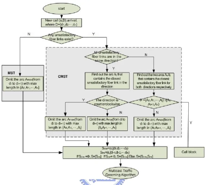
Since we have known that each kind of route can be represented by the absence of an arc in Arc(s,D), here, we propose an multicast routing scheme to choose which arc to be absent. In this scheme, we assume that the source node has the information of remained capacity on each wavelength of all fiber links. So we can know which fiber link in the network can’t satisfy the bandwidth request. A fiber link that can’t satisfy the bandwidth request means the remained capacity on each wavelength of the link is less than the bandwidth request. We call these fiber links “unsatisfactory fiber link” and the set consists of all unsatisfactory fiber links is denoted by Fu. Fig. 4.1 is the flowchart of multicast
routing scheme, the main idea of the scheme is to adaptively route a new call with least resources according to the link states. First, we would check if there is any unsatisfactory fiber link. If there were no unsatisfactory fiber links, we would omit the arc with maximum length. It means we use MST to be the route of the new call. We use MST due to that the least resources is used in MST. If there were unsatisfactory fiber links, we would check the direction of all unsatisfactory fiber links. After the direction has been checked, we used constraint minimum spanning tree (CMST) to route the new call. The CMST is the route in which the least resources are used under the constraint that there were unsatisfactory fiber links. We would find the arc with maximum length under the condition and omit the arc. If the omitted arc is qd di i+1 , the traffic from source s to {d1,
d2…,di} would use fiber links in counterclockwise and from source s to {di+1, di+2… dn}
will use fiber links in clockwise. Since the route contains two parts: one uses counterclockwise and another one uses clockwise. So we divide the new call into two sub-calls: counterclockwise sub-call, denoted by Sccw with source s and destination set {d1,
d2…,di}, clockwise sub-call, denoted by Scw with source s and destination set {di+1,
di+2… ,dn} according to the route. Note that if di =s or di+1 =s, the sub-call Sccw or Scw
sub-calls in S one by one. The multicast routing scheme can find the route for a new call and divide the new call into sub-calls to groom. Because we use least resources to route a multicast new call in the scheme, there would be more resource for future call and the blocking probability would also be reduced. The following are the steps of multicast traffic routing algorithm:
Algorithm Multicast Traffic Routing BEGIN
STEP 1: Set d0=s D={d1,d2,…,dn} Arc(s, D) = {A0, A1… An},,
Ai=d dqi ( 1)i+ ∀ =i 0,1,...,n - 1and An=d d ; qn 0
STEP 2: If ∀ ∈i Fcw∪Fccw ∃w st. F i w( , )≥R
Then applied MST:
Find the arc qd dl l+1 with maximum length in Arc(s, D); Let Sccw={ ,{ , ..., }}s d d1 2 dl Scw={ ,{s dl+1,dl+2..., }}dn ; S={Sccw,Scw};
Else, applied CMST: go to STEP 3 Endif;
STEP 3: If ∀ ∈i Fu in the same direction
Then Find the arc Aj contains the fiber link closest to source in the direction;
If∀ ∈ i Fu i∈Fcw then Find the arc d dql l+1 with maximum length in the set {Aj, Aj+1… An};
S={Sccw,Scw};
Else, Find the arc qd dl l+1 with maximum length in the set {A0, A1… Aj};
Let Sccw={ ,{ , ..., }}s d d1 2 dl Scw={ ,{s dl+1,dl+2..., }}dn ; S={Sccw,Scw};
Endif;
Else, go to STEP 4;
Endif;
STEP 4: Find the arc Ai and Aj contains the fiber link closest to source in both
directions respectively;
If {Ai, Ai+1…An} ∩{A0, A1…Aj}≠φ
Then Find the arc qd dl l+1 with maximum length in the set {Ai, Ai+1… Aj};
LetSccw={ ,{ , ..., }}s d d1 2 dl Scw={ ,{s dl+1,dl+2..., }}dn ; S={Sccw,Scw};
Else, block the new call;
Endif;
4.2 Multicast Traffic Grooming With Maximum Utilization
After using the adaptive routing scheme, we need to consider how to arrange the new call into the ring network. Instead of arranging the whole call at once, we divide the new call into to two sub-calls according to the route we have decided. As mentioned above, if an arc qd di i+1 is absent, the new call was divided into two sub-calls Scw and Sccw, wearrange the two sub-calls one by one. The sub-call can be arranged into network by two ways: grooming with current lightpaths and setting up new lightpaths. So the traffic-grooming problem can be divided into two subproblems: (a) grooming subproblem (b) wavelength assignment subproblem. The two subproblems are described as follow:
(a) Grooming subproblem
The utilization efficiency of used wavelengths increases as long as the traffic of sub-call can be groomed with the lightpaths. This subproblem is considered as how to groom the traffic into lightpath suitably according to the route of a sub-call. We propose a grooming scheme to find which lightpath is suitable. The sub-call is not groomed with random lightpath in the scheme. Instead, we find the lightpaths according to the relationship of the source and the destinations, and consider the lightpath has the maximum number of destinations, which are the same as the destination of the new call first. The grooming scheme also contains two parts: direct grooming and partial grooming. We will introduce the operation of grooming block in detail in next section. The grooming block is very important because it not only increases the utilization of wavelengths but also reduces the new call blocking rate.
(b) Wavelength assignment subproblem
This subproblem is how to assign a wavelength to create new lightpaths. In this
subproblem, we must assign wavelength under the constraint which any two lightpaths pass through the same fiber link are assigned different wavelengths. This subproblem is
considered if we can’t find suitable lightpaths to groom. We need to assign wavelength to setup new lightpaths. Although many wavelength-assignment approaches were proposed, all of they were found to perform similarly. Because of the result, we will choose the simple approach, first-fit, to solve the wavelength assignment subproblem. In first-fit, all wavelengths are numbered as 1, 2, 3…W. When we want to setup a new lightpath, we will search a available wavelength according to number. If there is a lower numbered available wavelength, it will be considered first.
We have described the two subproblems of traffic grooming. We start to expound our scheme in detail. As mentioned above, before we start to arrange the new call into the network, the new call would be divided two sub-calls: Sccw and Scw according to the route.
Let S1 denote the first element in S and D denote the destination set of Ss1 1. We would
arrange the two sub-calls in S in turn. So we would arrange sub-call S1 first.
Fig. 4.2 is the flowchart of traffic grooming algorithm. From the flowchart, we can see we try to arrange the sub-call with grooming first. Our grooming block contains two parts: direct grooming and partial grooming. We first try to find a direct lightpath to direct groom with the sub-call. A direct lightpath is a lightpath that has the same source and terminating node as the source and terminating node of the sub-call and the lightpath must have enough capacity to accept the bandwidth request. Note that the number of destinations of such lightpath after grooming with the sub-call must less or equal to kmax. If
we directly groomed successfully, the arrangement of the sub-call would end. And then we would start to arrange the next sub-call if there was still another sub-call.
If we could not find a direct lightpath to directly groom with the sub-call, we would start to find a lightpath to partially groom the sub-call. In partial grooming block, co-destination lightpaths and partial-destination lightpaths can be used to partially groom. We search a co-destination lightpath first. A co-destination lightpath is similar to direct
lightpath but is allowed to have different source as the source of the sub-call. If there is no co-destination lightpath, we search a partial-destination lightpath. A partial-destination lightpath has the same source as that of the sub-call and the terminating node of the lightpath is one destination of the sub-call. There may be several partial-destination lightpath. We would choose the one, which contains maximum number of destinations of the sub-call to partial groom. No matter we use co-destination lightpath or partial-destination lightpath, only partial of the sub-call is arranged into network. After partial grooming by a co-destination lightpath or partial-destination lightpath, the remained part of the sub-call forms a new sub-call. So we redo above action (direct grooming and partial grooming) until we can’t find any lightpath to groom or the whole sub-call has been groomed.
Apparently, it is easier for a unicast call than for a multicast call to find a lightpath to groom since it is easier to find a lightpath that has the same source and destination as the source and destination of a unicast call. So the new sub-call after partially grooming with co-destination lightpath is easier than the one after partially grooming with partial destination lightpath to find a lightpath to groom. This is the reason we search a co-destination lightpath first.
After the grooming block, the whole sub-call or partial sub-call may not be arranged into the ring by grooming. We need to setup new lightpaths for the whole sub-call or partial sub-call. As we has described in wavelength subproblem, we use first-fit to search free wavelength to setup a new lightpath. If we setup new lightpaths successfully, the arrangement of the sub-call ends. In such condition, the sub-call may be severed by provisioned lightpaths and new lightpaths. If we can’t find a free wavelength to setup new lightpath, the whole new call would be blocked.
Then, we give some notations we used in the algorithm. The source of the sub-call we want to arrange is denoted bys . The destination set of the sub-call is denoted bys D and s
the ith destination along the direction of the sub-call is denoted by
i
s
d . The source of a
co-destination lightpath is denoted byscd. L s Dp( ,s s) denotes the lightpath set that contains all possible partial-destination lightpath for ( ,s D . The destination set covered s s) by a partial –destination lightpath ( , , is denoted by
i s s s d w ) ( , , ) i p s s D s d w . Then when a new call (s, D) is routed successfully, we get the sub-call set S for (s, D). Then, the traffic -grooming algorithm starts with the following steps:
Algorithm Multicast Traffic Grooming BEGIN
STEP 1: Setss =s,
1
s s D =D ;
STEP 2: If any direct lightpath for (s ,s D ) exist s
Then Direct grooming with the direct lightpath; S=S-{S1};
S=S-{S1};
If S ≠φ
ThenS1=S2;
Go back to Step (1);
Else, the algorithm terminate; Endif
Endif;
STEP 3: If any co-destinations lightpath for (s ,s D ) exist s
Then Partial grooming with the co-destination lightpath;
s
Go back to Step (2); Endif;
STEP 4: If Ds ≠ 1
Then find all possible partial-destination lightpath and let L s Dp( ,s s) be the set contains all partial-destination lightpath
If L s Dp( ,s s)≠φ Then * * ( , , ) ( , ) ( , , ) arg max ( , , ) i i s si p s s s s p s d w L s D s d w D s d w ∈ = s s
Partial grooming with the partial-destination lightpath( , *, *);
i s s s d w * i s s s =d , ( , *, *) i s s p s s D =D −D s d w ; Go back to Step (2); Endif; Endif; STEP 5: If D >S kmax
Then if ( D modS kmax)≠0
Then for i=kmax to (D modS kmax)
If any wavelength which is not used froms tos dsi exist
Then Establish the new lightpath froms tos dsi ;
i s s s =d ; 1 2 { , .... } i s s s s s D =D − d d d ; Go back to Step (2); Endif;
Endfor;
Else if ( D modS kmax)= 0
Then if any wavelength which is not used froms tos exist
max
k
s
d
Then Establish the new lightpath froms tos
max k s d ; max k s s s =d ; ; 1 2 max { , .... } k s s s s s D =D − d d d Go back to Step (2); Endif; Endif;
Block the new call;
Endif;
STEP 6: If any wavelength which is not used from (s ,s D ) exist s
Then Establish the new lightpath for (s ,s D ); s S=S-{S1};
If S ≠φ
ThenS1=S2;
Go back to Step (1);
Else, the algorithm terminate; Endif;
Else, block the new call Endif;
S≠Φ
Direct grooming The direct lightpath for (ss, Ds) exist? Co-destination lightpath for (ss, Ds) exist ? Partial grooming Partial-destination lightpath set Lp(ss, Ds)≠Φ? ss=s, Ds=Ds1 |Ds|<=1? Partial grooming S=S-{S1}, Call block end Y N Y N N Y Y N Direct Grooming Partial Grooming Wavelength Assignment S1=S2
Multicast Traffic Routing Algorithm * * ( , , ) ( , ) ( , , ) argmax ( , , ) si p s s s i p s i s d w L s D s d w D s d w ∈ = s s cd s s D s = = * * ( , , *) i i s s s s p s s s d D D D s d w = = − |Ds|>kmax |Ds|%kmax=0 N N Y max ,
Any free wavelength for ( ) k s s s d max ,
Estiblish new lightpath for ( )
k
s s s d
,
Any free wavelength for (s Ds s)
,
Estiblish new lightpath for (s Ds s) max 1 2 max { , .... } k k s s s s s s s s d D D d d d = = − max max , For to (| | % ) any free wavelength for ( ) i s s s i k D k s d = ,
Estiblish new lightpath for ( ) i s s s d Y N Y Y N 1 2 { , .... } i i s s s s s s s s d D D d d d = = − N N
Chapter 5
Simulation Result
Chapter 5 Simulation Result
n this section, we show the performance of the MUMO scheme and the comparisons with other grooming schemes in the same configuration. We also reveal the performance of the MUMO scheme with respect to various parameters. In the network we simulated, there are two fibers between any two adjacent nodes and each fiber contains 20 wavelengths. The capacity of each wavelength is OC-48 (2.5G/s). The MUMO scheme was compared with other schemes in different cases. First, we compare the performance of the MUMO and other schemes as the traffic load increases. Then, we also compare the performance as the ratio of multicast calls increases. Finally, we compare the performance as the maximum number of destinations of a multicast call increases. The simulation results of the comparisons in these cases are presented and discussed.
I
After discussing simulation results of the comparisons, we also reveal the performance evaluation of various network parameters. Four kinds of network parameters are used to compare the performance. We evaluate the performance with various mean service rateμm. The difference between different mean service rates will be presented and discussed. Then, we evaluate the performance with various number of network nodes N. We will discuss the effect of number of network nodes. We also evaluate the performance with various ratio of the probability among difference type of traffic. Finally, the performance with
different kmax is simulated.
Before illustrating the comparison among the MUMO and other conventional schemes, we give a brief introduction of the three schemes. The MUMO scheme is compared with the two schemes: Single-Hop (SH) and Hybrid Multi-Hop (HYMH). When a new call arrivals at the ring network, SH will decide the route by MST routing scheme. Then, the SH scheme checks if any existing lightpath with available bandwidth has the same source and destinations as the source and destinations of the new call. If such a lightpath is found, the new call will be groomed with the lightpath; else it tries to set up new lightpaths for the new call. If the scheme even cannot setup new lightpath, the new call will be blocked. The HYMH will also decide the route by MST, but in the scheme, a new call can be served by combination of multiple provisioned and un-provisioned lightpaths. The scheme searches for a lightpath that has the same destinations as the destinations of the new call. The lightpath is called “to destination lightpath" (TDLP) . If TDLP is found, the scheme will search the other lightpaths or set up new lightpaths from the source of new call to the source of TDLP. The lightpath is called “from-source lightpath” (FSLP). If TDLP is not found, the scheme will setup new lightpaths for the new call.
Two performance measurements for MUMO, SH and HYMH are revealed. The first is about the new call blocking rate of the three schemes. The second is about the utilization efficiency of the used wavelength of the three schemes. According to these issues, there are two kinds of graphs in the simulation.
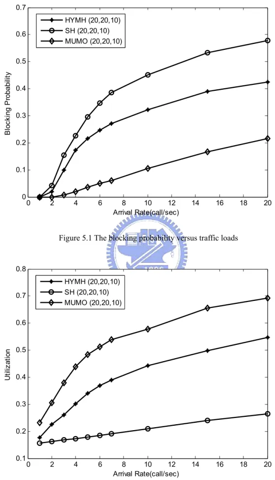
In the following figures from Fig. 5.1 to Fig. 5.6, the network parameters: W=20, N=20, C=48, kmax=10, μm=0.05, R= {1, 3, 12, 16}, ( ,p p1 2,p3,p4)= (0.25, 0.25, 0.25, 0.25) is
considered. As for the multicast ratio, the arrival rate and the max number of destination of a multicast call, we will give these parameters for each different figure. Fig. 5.1 and Fig. 5.2 show the blocking probability and the utilization efficiency of the used wavelength
0 2 4 6 8 10 12 14 16 18 20 0 0.1 0.2 0.3 0.4 0.5 0.6 0.7 Arrival Rate(call/sec) B loc ki ng P ro ba bi lit y HYMH (20,20,10) SH (20,20,10) MUMO (20,20,10)
Figure 5.1 The blocking probability versus traffic loads
0 2 4 6 8 10 12 14 16 18 20 0.1 0.2 0.3 0.4 0.5 0.6 0.7 0.8 Arrival Rate(call/sec) U til iz at io n HYMH (20,20,10) SH (20,20,10) MUMO (20,20,10)
versus traffic load, respectively, where the ratio of multicast call is 0.5 and the max number of destination of a multicast call is 19. It can be seen that the blocking probability of the MUMO scheme is much less than that of the other two schemes and the utilization efficiency of the MUMO scheme is much higher that of the others. It is because the MUMO scheme can partially groom the multicast traffic. It is easier to find lightpaths to groom a multicast call by the help of partially grooming. In addition, the other two schemes must find a lightpath which has the same destinations as the destinations of the new call while the MUMO scheme does not need. Moreover, since the routing approach of MUMO can always find a route with minimum hops according to the link state, the MUMO scheme can avoid choose the route that cannot satisfy the new call request. The blocking probability can be reduced by the routing approach of the MUMO scheme. On the other hand, the routing scheme of the other two schemes cannot adaptively choose the route, and the blocking probability is then larger.
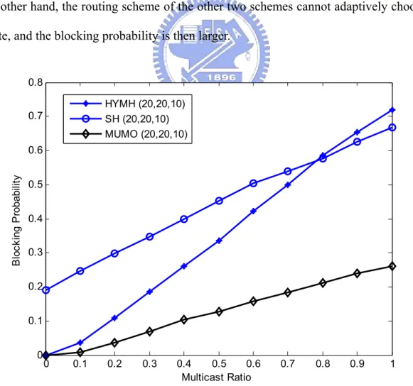
0 0.1 0.2 0.3 0.4 0.5 0.6 0.7 0.8 0.9 1 0 0.1 0.2 0.3 0.4 0.5 0.6 0.7 0.8 Multicast Ratio B loc ki ng P ro ba bi lit y HYMH (20,20,10) SH (20,20,10) MUMO (20,20,10)
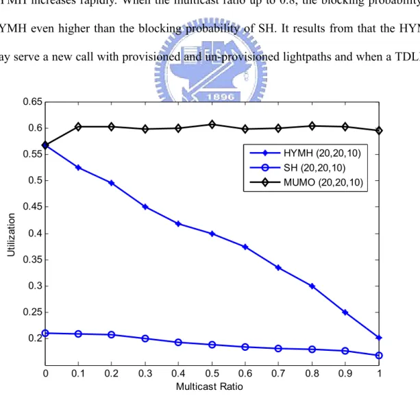
Fig. 5.3 and Fig. 5.4 show the blocking probability and utilization of used wavelength versus the ratio of multicast calls, respectively, where, The arrival rate is 10 (call/sec) and the max number of destinations of a multicast call is 19. From Fig. 5.3, it can be seen that the blocking probabilities increase as the multicast ratio increases, but that of the MUMO scheme increases much slower than that of the other two schemes. It is because that the SH and the HYMH cannot groom partially, they cannot deal with the multicast traffic efficiently. Beside, as mentioned above, the MUMO scheme only needs to find the lightpath that has the same terminating node; it helps a multicast call finding lightpaths to groom. From Fig. 5.3, it also can be found that the HYMH can have good performance when all traffics are unicast. As the multicast ratio increases, the blocking probability of HYMH increases rapidly. When the multicast ratio up to 0.8, the blocking probability of HYMH even higher than the blocking probability of SH. It results from that the HYMH may serve a new call with provisioned and un-provisioned lightpaths and when a TDLP is
0 0.1 0.2 0.3 0.4 0.5 0.6 0.7 0.8 0.9 1 0.2 0.25 0.3 0.35 0.4 0.45 0.5 0.55 0.6 0.65 Multicast Ratio U til iz at io n HYMH (20,20,10) SH (20,20,10) MUMO (20,20,10)
found, the HYMH scheme may setup a new lightpath from the source to the source of TDLP. There must be only one destination on the new lightpath. Since the HYMH scheme need to find a lightpath has the same destinations as the destinations of the new call, these lightpaths may be groomed hardly when the multicast ratio is high. These lightpaths will waste the capacity and even result in that a lightpath only used by a single call, and the blocking probability of the HYMH scheme is then greater than that of the SH scheme when multicast ratio is high. From Fig. 5.4, similar condition can be seen that the utilization of HYMH decreases rapidly and finally becomes similar to the utilization of SH. As for the MUMO scheme, it has good performance no matter in which multicast ratio.
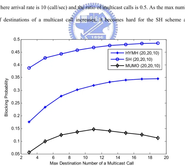
Fig. 5.5 and Fig. 5.6 reveal that the blocking probability and the utilization of used wavelength versus the maximum number of destination of a multicast call, respectively, where arrival rate is 10 (call/sec) and the ratio of multicast calls is 0.5. As the max number of destinations of a multicast call increases, it becomes hard for the SH scheme and
2 4 6 8 10 12 14 16 18 20 0.05 0.1 0.15 0.2 0.25 0.3 0.35 0.4 0.45 0.5
Max Destination Number of a Multicast Call
B loc ki ng P ro ba bi lit y HYMH (20,20,10) SH (20,20,10) MUMO (20,20,10)
HYMH scheme to find a lightpath that has the same destinations as the destinations of new call. Then, the blocking probabilities of the two schemes increase slowly. As for the MUMO scheme, from Fig.5.5, when the number of destinations is less than 11, the blocking probability of the MUMO scheme also increases. But after the number of destinations is larger than 11, the blocking probability of the MUMO scheme starts to decrease. It is because when the number of destinations large enough, the new call may be usually divided into two sub-calls; it helps the new call finding lightpaths to groom. Beside, when the number of destinations large enough, it is easier for the MUMO scheme to search a partial-destination lightpath. It is also the reason make the blocking probability of the MUMO scheme decreases as the max number of destination of a multicast call is large. The utilization of used wavelength is shown in Fig. 5.6. Since the blocking probability of the HYMH scheme increases as number of destination increases, the utilization of the HYMH scheme decreases. The utilization of MUMO increases as the.
2 4 6 8 10 12 14 16 18 20 0.2 0.25 0.3 0.35 0.4 0.45 0.5 0.55 0.6 0.65
Max Destination Number of a Multicast Call
U til iz at io n HYMH (20,20,10) SH (20,20,10) MUMO (20,20,10)
destination large enough since the blocking probability decreases. Beside, because of partially grooming, a new call may be served by multiple lightpaths. Thus, a new call may increase the utilization of multiple lightpaths. For the MUMO scheme, the utilization of large number of destinations is even higher than the utilization of small number of destinations.
After we discuss the performance comparisons of the three schemes in the fixed environment, the performance evaluations with various network parameters setting are then discussed and presented. In the following figures, most of the network parameters are the same as above except for the parameter which used to evaluate the difference of performance.
Fig. 5.7 and Fig. 5.8 show the blocking probability and the utilization of used wavelength with different mean service rate, respectively. Two mean service rate: 0.05 and 0.02 are simulated for the HYMH scheme and the MUMO schemes. It can be found that the blocking probability of low service rate is higher than high service rate. As the service rate is low, the bandwidth is occupied by a call for a long time. Then, the low service rate will result in that it is hard to arrange a new call into the network. Although MUMO always has better performance, the gap of blocking probability between the MUMO scheme and the HYMH scheme decreases as the service rate is low. It is because that the calls, which successfully arranged by the MUMO scheme, are much more than that of the HYMH scheme, the blocking probability of the MUMO scheme will increase more as the service rate is low. About the utilization, since low service rate has long service time, the utilization of used wavelength is higher. However, the gap between the two schemes also decrease as the service rate is low. It is because that the utilization of the MUMO scheme is almost saturated even the service rate is high, so the increased utilization is limited.
2 4 6 8 10 12 14 16 18 20 0 0.1 0.2 0.3 0.4 0.5 Arrival Rate(call/sec) B loc ki ng P ro ba bi lit y
MUMO, Mean Service Rate=0.05 MUMO, Mean Service Rate=0.02 HYMH, Mean Service Rate=0.05 HYMH, Mean Service Rate=0.02
Figure 5.7 The blocking probability with different mean service rate
2 4 6 8 10 12 14 16 18 20 0.1 0.2 0.3 0.4 0.5 0.6 0.7 0.8 0.9 Arrival Rate(call/sec) U til iz at io n
MUMO, Mean Service Rate=0.05 MUMO, Mean Service Rate=0.02 HYMH, Mean Service Rate=0.05 HYMH, Mean Service Rate=0.02