OPTIMAL SECURITY PATROLLING BY MULTIPLE VISION-BASED
AUTONOMOUS VEHICLES WITH OMNI-MONITORING
FROM THE CEILING*
Hsing-Chia Chen (陳倖嘉) and Wen-Hsiang Tsai (蔡文祥)
Institute of Multimedia Engineering, College of Computer Science
National Chiao Tung University, Hsinchu, Taiwan 300
Abstract-A multiple vision-based vehicle system for
security patrolling in an indoor environment is proposed. Multiple autonomous vehicles controllable by wireless communication and equipped with cameras, as well as top-view omni-cameras with fish-eye lenses fixed on the ceiling are used as a test bed. First, a method is proposed for collecting navigation environment information, including vehicle turning points and object monitoring points, so that the vehicles can navigate to visit monitored objects without collisions with walls. Next, a point correspondence technique integrated with an image interpolation method is proposed for camera calibration by which the top-view cameras can be utilized to learn the information that enables vehicles to perform the security monitoring task, to locate the vehicles, and to monitor vehicle activities in the navigation phase. An optimal randomized and load-balanced path planning method is proposed as well, which requires shorter time to accomplish object monitoring in one session and provides higher degrees of patrolling security. Good experimental results show feasibility of the proposed methods for the application of multiple-vehicle security patrolling.Keywords: vision-based autonomous vehicle, security
patrolling, optimal path planning, vehicle location, top-view cameras.
1. Introduction
Traditional security surveillance systems, mostly consisting of cameras, are passive in the sense that it’s the camera positions are fixed and the acquired images have fixed fields of views. By the ability of dynamic movement, a vision-based autonomous vehicle on the contrary is more appropriate for security patrolling in indoor environments. When a vehicle detects an abnormal state about a monitored object, it can send an alert message to the security center actively. In this paper, an optimal security patrolling system consisting of multiple vision-based autonomous vehicles with omni-monitoring from the ceiling is proposed.*
To decrease time taken to complete one session of patrolling all monitored objects, multiple vision-based autonomous vehicles are used. A good planning of patrolling paths for all vehicles is also necessary to yield
* This work was supported by the Ministry of Economic Affairs under
Project No. MOEA 96-EC-17-A-02-S1-032 in Technology Development Program for Academia.
better patrolling performances. For this purpose, the three critical principles of randomization, optimization, and
load balancing are considered in the proposed path
planning scheme. Random vehicle patrolling processes make thieves have no idea about when an object is not monitored by any vehicle. Optimal path planning and load balances among all vehicles aim to decrease the total patrolling time. Additionally, shortening the time interval between two patrollings over a monitored object area is also considered to increase the degree of security.
In order for a vehicle to carry out the patrolling task automatically, processes for learning path nodes, locating the vehicle position constantly, and performing the security monitoring task are also proposed. For vehicle calibration which is required in the learning process, many techniques [1-7] have been proposed. But most of them are based on the assumptions of having pure-colored backgrounds, using robust features, or navigating in ideal environments. Therefore, top-view omni-cameras with fish-eye lens are utilized in this study to widen the applicable environment, which is inspired by a technique by Lai and Tsai [8]. By the use of a technique of finding corresponding points in 2-D image and 3-D global spaces as well as an image interpolation method, the correct positions of interesting feature points can be obtained from the warped images captured by the top-view cameras. Besides, a faster point-correspondence technique is proposed to obtain corresponding points in image pairs that yield better calibration accuracy. The proposed techniques are described in the following sections.
2. Learning Strategies for Navigation by
Semi-automatic Driving
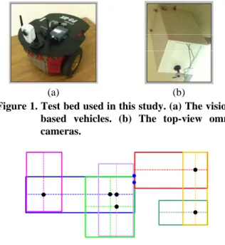
The vision-based vehicles and the top-view omni-cameras used as a test bed in this study are shown in Fig 1. A notebook PC is used to integrate the entire security patrolling system. Through wireless networks, the images captured by the cameras equipped on the vehicles or by those fixed on the ceiling can be analyzed by the PC for the vehicles to perform corresponding actions according to the commands produced by the PC. For the purpose of enabling the vehicles to accomplish the patrolling mission successfully, data having to be recorded are categorized into area-related, camera-related, and object-related ones.
Area-related data are about the environment where the
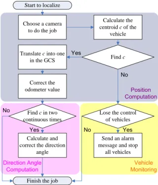
vehicles patrol. At first, the corner points of the walkable area are utilized to acquire all rectangular regions, and
then some turning points in the overlapping or adjacent regions are calculated. By the turning points, the vehicles can navigate between any two nodes without collisions with the walls. As an example, Fig. 2 shows seven rectangle regions composing an area and eight turning points represented by circular dots.
(a) (b)
Figure 1. Test bed used in this study. (a) The vision-based vehicles. (b) The top-view omni-cameras.
Figure 2. Rectangle regions and turning points in an area.
Figure 3. Finding all corresponding point pairs.
Figure 4. An example of learning a monitoring point.
Camera-related data are obtained from a camera
calibration process. For camera calibration, we record corresponding points in 2-D images of a calibration target (see Fig. 3) and the corresponding 3-D global space, and find the actual position in the global space by a bilinear interpolation method. Some advantages of the method over the traditional projection-based transformation [9] are its higher speed and better calibration accuracy, because multiplications and angle operations are reduced. The calibration target is taken to be the environment floor and the intersections of the tiles on the floor are taken as the reference points for point correspondence. To acquire more corresponding points faster, we calculate quadratic curves in the image of the floor, utilizing three points at least for each curve by minimum mean-square-error (MMSE) curve fitting, and then find the intersections of the curves as the desired reference points in the 2-D space. One reference point and it corresponding one in 3-D space is exactly one corresponding point pair. A result of finding all corresponding points from the image of one top-view omni-camera is shown in Fig. 3.
3. Vehicle Navigation and Object Monitoring
Vehicles are subject to accumulation of mechanic errors as shown in Fig. 5, in which the straight path from node O to node A is desired, but the vehicle will actually move through a curve from node O to node B. So, the position and the direction angle of each vehicle must be calibrated after moving a fixed distance. Utilizing the top-view cameras to analyze absolute vehicle positions from top-view images, the vehicle odometer can be corrected. To reduce noise influence and the calculation time of finding out the vehicle position, we only process a region in the image, whose center is the odometer value of the vehicle and whose width is a pre-selected value, as shown in Fig. 4. To calculate the centroid of the vehicle,
background subtraction, erosion, dilation, and region growing are used. This process of finding out the centroid
of the vehicle is illustrated in Fig. 6. Then, the absolute vehicle position is obtained by transforming this centroid into the global space. If the number of components is larger than one, it is necessary to find out the one which is more like a vehicle by the shape or the number of the pixels in the component. Furthermore, if no component is found according to the odometer value, the state is that there is one vehicle which is not under control, for which the system will send a message to the control center.
Object-related data are used to accomplish the
patrolling task by vehicles. Because the vehicles suffer from mechanic errors, the monitoring points where monitored objects are in the view of the vehicles are learned by vehicle localization using the top-view cameras, and then two correct positions are utilized to acquire a direction vector toward an object. An example of learning
a monitoring point is shown in Fig. 4. angle is θAbout the direction angle shown in Fig. 5, the correct 1. Because the distance between two continuous vehicle localizations is short, the curve path is close to a
straight line. We can correct the direction angle of the vehicle by θ2 obtained by two continuous correct positions. A flowchart of localizing and monitoring vehicles is shown in Fig. 7.
1
θ
2
θ
Figure 5. The vehicle suffers from mechanic errors.
Figure 6. Finding the actual position of a vehicle. (a) A binary image by background subtraction. (b) Erosion of (a). (c) Dilation of (b). (d) The connected component of (c) and the computed centroid (the white circle).
In the navigation phase, the vehicles navigate along assigned patrolling paths by orderly arriving at the learned nodes, including monitoring points and turning points. The idea of using such nodes as guidance points comes from a learning method proposed by Chen and Tsai [10]. By the current node and the goal node, we can obtain the direction vector and then the rotation angle θturn. Each vehicle turns to the angle θturn and moves forward. When a vehicle has moved a certain distance d, it is localized. Furthermore, if the vehicle arrives at a goal node which is a monitoring point, the direction angle of the vehicle must be adjusted as the one θMP obtained in the learning phase before performing the security monitoring task. A flowchart is shown in Fig. 8.
4. Planning of Optimal Randomized
Patrolling Paths for Vehicles
Path planning is an important topic for security patrolling by multiple vehicles. Many methods for this aim have been proposed in [11-13]. Besides, load balancing among all vehicles also need to be paid attention. Hert and
Richards [14] proposed a method of using a polygon partitioning algorithm to achieve this objective. In this study, we use multiple vision-based autonomous vehicles to perform security patrolling. By an optimal randomization technique proposed in this study, patrolling paths with the properties of randomization, optimization, and load balancing within all vehicles can be generated. The details are described in the following.
Start to localize Choose a camera to do the job Calculate the centroid c of the vehicle
Translate c into one
in the GCS Find c
Correct the odometer value
Lose the control of vehicles
Send an alarm message and stop
all vehicles
Finish the job Find c in two continuous times
Calculate and correct the direction
angle Yes Yes No Yes No No Direction Angle
Computation MonitoringVehicle
Position Computation
Figure 7. Flowchart of locating and monitoring vehicles.
Figure 8. Flowchart of guidance and object monitoring.
Let the total number of vehicles and monitoring points (MPs) be nv and nm, respectively. In the proposed method for generating random patrolling paths, we divide all MPs into nv groups randomly. Assume that the number of chosen MPs for the i-th vehicle is ni, so that the numbers
can be represented as (n1, n2, ..., nnv). Each ni must satisfy two conditions as listed in the following.
Condition 1: n1 + n2 + ...+ nnv = nm − nv, Condition 2: m v m v , i v v n n Tv n n n Tv n n ⎢ ⎥ ⎡ ⎤ ⎢ ⎥ ⎢ ⎥ ⎣ ⎦ ⎢ ⎥ − − ≤ ≤ − +
where Tv is an adjustable parameter and i = 1, 2, ..., nv. Because nv MPs are patrolled by nv vehicles at the end of the t-th session, there is no need to visit the nv MPs again in the (t+1)-th session. This is the reason why the value “nm - nv” is included in Condition 1. Additionally, the purpose of Condition 2 is to achieve load balancing among all vehicles. Because we set a threshold parameter T to restrict the differences of the patrolling distances, each ni dose not have to be equal to the mean m v
v n n n ⎡ − ⎤ ⎢ ⎥ ⎢ ⎥ or m v v n n n ⎢ − ⎢ ⎣ ⎦ ⎥
⎥. Therefore, we add the parameter Tv to obtain
an upper bound “ m v v n n n ⎡ − ⎢ ⎢ ⎥ ⎤
⎥ +Tv” and a lower bound
“ m v v n n n ⎥ − ⎥ ⎣ ⎦ 1 2 1 1 1 2 ... , ,... m v n m v m v v nv n n n n n n n n n n n n n C − C − − C − − − − − − ⎢
⎢
-
Tv” for all ni. The parameters Tv and T areadjustable. If they are smaller, the time taken to determine all patrolling paths is larger, but the loads of all vehicles will be more balanced. The state of choosing MPs for all vehicles can be represented as
( , ),
where the combination value is the number of picking
k MPs from n MPs randomly, defined as
n k C ! n n n C ≡⎛ ⎞≡ 1 2 1 1 1 2 1 2 ... ( , ,..., ) ( m v, m v ,..., m v nv ) nv nv n n n n n n n n n n n n n n n n C − C − − C − − − − − −
∑
!( - )! k k k n k ⎜ ⎟ ⎝ ⎠.
The total number of random patrolling paths so is
.
As long as one group of MPs is determined, we calculate next a path passing all of the MPs under the constraint that the distance of the path is the shortest. For the monitored objects to be patrolled uniformly, each MP is just passed one time. That is, the difference between the biggest and the smallest times of MPs passed at any moment is desired to be one or zero. In this sense, each
MP will be visited t times at the end of the t-th session of
security patrolling. And then the system will calculate new patrolling paths for the next session. Because it is desired to get the shortest distance path by which each assigned
MP is visited only once, the problem can be solved as a traveling salesman problem (TSP). Some methods for
solving the TSP can be found in [15-17]. To solve the problem as a TSP, the information of the distance between each pair of MPs is needed. In this study, the floor shape of a vehicle patrolling environment is assumed to be composed of rectangular regions. There may be two MPs
which do not belonging to the same region. If two MPs are in different regions, the vehicle might not be able to move along a straight path between them without hitting obstacles. To obtain the distance between every pair of
MPs, we must judge whether one pair of MPs belong to an
identical rectangular region. If yes, the distance of this pair is the straight distance between them; else, the straight path between them must be abandoned and a new path with multiple line segments should be planned using some turning points obtained in the learning phase. Because the between-MP distance is desired to be the shortest, it can be figured out that the distance may be computed by
Dijkstra’s algorithm [18].
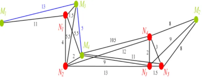
As an example, a patrolling environment is shown in Fig.9, in which M1 through M4 are monitoring points, and
N1 through N5 are turning points. Furthermore, each black edge connects two points which are in an identical rectangular region and each blue edge connects two monitoring points which are also in the same one. All distances between pairs of monitoring points and turning points passed by them are recorded in a table, as shown in Table 1.
Figure 9. A patrolling environment.
Then, we transform the graph in Fig.9 into another, as shown in Fig.10. With the complete undirected graph and all distances, we can find an optimal patrolling path. Because the vehicles do not return to the start position as assumed in this study, the path is exactly a Hamiltonian
path with the minimum distance. The result of Fig.10
starting at M1 is M1→M3→M4→M2
.
And then integrating the information of Table 1 into the path, we get the final result as M1→M3→M4→N4→M2. To achieve the optimal randomized patrolling paths for all vehicles, we set a threshold parameter T to restrict the differences of the patrolling distances for the property of load balancing among vehicles. If the condition is not satisfied, all monitoring points will be chosen and the patrolling paths will be calculated again.5. Experimental Results
We show some experimental results of the proposed security patrolling system by two ways. The first is the result of optimal randomized patrolling paths shown by a simulation using programs written in the Borland C++ builder. The other is the result of conducting the navigation in an actual environment.
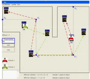
In the simulation, we create a patrolling environment whose floor shape is composed of four rectangular regions,
as shown in Fig. 11, in which Obj. 0 (M0) through Obj.6 (M6) are monitoring points. For example, the first vehicle starts its navigation at M4 and the second vehicle starts at
M1. Among all monitoring points, M0, M3, M4, and M6 are chosen by the first vehicle; M1, M2, and M5 are chosen by the second. The obtained optimal paths are
M4→M6→M3→M0 and M1→M2→M5, respectively. According to the record of turning points passed by between each pair of monitoring points, obtained in the learning phase, the actual paths are
M4→M6→N3→M3→N1→M0 and M1→M2→N2→N3→M5, respectively, as shown by red and green dotted lines in Fig. 11. Furthermore, the distances of the paths are 1633.22 and 1081.56. Because the difference of the distances is smaller than the threshold 800, set by the user, the two paths are accepted.
Table 1. Distances and passing turning points between every pair of monitoring points.
M1 M2 M3 M4 M1 37 13 16.5 M2 N1→N2→N3 (M1→M2) 25.5 18.5 M3 N4→N2 (M2→M3) 5 M4 N1 (M1→M4) N4 (M2→M4)
Figure 10. A complete undirected graph.
To show the advantage of the proposed system, we compare the times needed for different control factors, as shown in Table 2. If the property of randomization is an essential condition, the average time in one session taken by using one vehicle is nearly double of that taken by using two vehicles. This result tells us that a system with multiple vehicles is advantageous. Besides, if the number of vehicles is the same, an optimal patrolling path will take less time than a non-optimal path.
The real environment for this experiment is an open space area in our laboratory. We drive the vehicle to twenty random places and record the values of the actual positions and the odometer. The total moved distance is 4818.40 centimeters and the average error rate without calibration by the top-view cameras between the actual positions and the odometer values is 8.86%. However, the average error rates with calibration are only 3.86% and 2.51 % for two top-view cameras.
Furthermore, the task of security patrolling includes the work of capturing the pictures of some monitored
objects. By the top-view omni-cameras to locate the vehicles periodically in the patrolling session, the vehicles can accomplish the mission with the information of the positions and the orientations with respect to the objects, obtained in the learning phase. As an illustration, we show some results of images taken by the vehicles. Some monitored objects are seen in the center of the images taken in the learning phase, as shown in Fig. 12(a). The images, captured by the vehicles in the patrolling session, corresponding to the ones in Fig. 12(a) are shown in Fig. 12(b).
Figure 11. Path planning for two vehicles in a session.
Table 2. Distances and passing turning points between every pair of monitoring points.
Number of Vehicles Randomization Optimization Average Time (second / one session) Saved Time/ Original Time (%) 1 O O 39.4 - 1 O X 31.6 19.8 2 O O 19.7 50.0 2 O X 13.5 65.7
6. Conclusions
In this study, we utilize multiple vision-based autonomous vehicles to develop a security patrolling system in an environment whose floor shape is composed of rectangular regions. We have proposed several techniques and algorithms for the system, including an environment-information calculation method to obtain all rectangular regions, which form the floor shape of the patrolling environment, the turning points, and then all between-MP distances and paths; a point correspondence technique integrated with an image interpolation method for camera calibration; a faster point-correspondence technique for camera calibration; a vehicle-pose learning
method, by which the vehicles are taught where and in which direction to perform the security monitoring task; an optimal method for randomized and load-balanced path planning, in which each MP is just passed once such that monitored objects can be patrolled uniformly; a vehicle localization and monitoring method, utilizing the top-view omni-cameras. The experimental results revealed the feasibility of the proposed system. Future researches may be directed to path planni cated
nvironments.
ng in more compli e
Figure 12
) Images captured in the navigation phase.
References
e,” Pattern Recognition, vol.
nd
botics, pp. 57-62, Atlanta, Georgi
ion & Measurement Technology, Italy,
rs,” Pattern Recognition, vol.
eter and house corner location
al Processing,
and Image Processing,
d Image Processing, Kinmen, Taiwan,
ce Hall, Upper Saddle River,
d Image Processing, Taipei, Taiwan,
botics and Automation, vol. 12, no. 4,
Automation, vol. 14, no. 3, pp. 427-436,
,”
. 109-116, Springer-Verlag,
cessing
ms, Man, and Cybernetics, vol.
nd edition. MIT Press, Cambridge, MA, USA, 2001.
(a) (b)
. The security patrolling task. (a) Images captured in the learning phase. (b
[1] I. Fukui, “TV image processing to determine the position of a robot vehicl
14, pp. 101-109, 1981.
[2] M. Betke and L. Gurvits, “Mobile robot localization
using landmarks,” IEEE Trans. on Robotics a Ber
Automation, vol. 13, no 2, pp 251-263,Apr., 1997.
[3] M. J. Magee and J. K. Aggarwal, “Determining the position of a robot using a single calibration object,”
IEEE Conf. on Ro a, S
USA, May 1983.
[4] J. Huang, C. Zhao, Y. Ohtake, H. Li, and Q. Zhao, “Robot position identification using specially designed landmarks,” Proc. of 2006 IEEE Conf. on
Instrumentat
Apr., 2006.
[5] H. L. Chou and W. H. Tsai “A new approach to robot location by house corne
19, pp. 439-451, 1986.
[6] K. L. Chiang and W. H. Tsai, “Vision-based autonomous vehicle guidance in indoor environments
using odom information,”
Proc. of 2006 IEEE International Conf. on Intelligent Information Hiding & Multimedia Sign
pp. 415-418, USA, Dec. 18-20, 2006.
[7] K. C. Chen and W. H. Tsai, “A study on autonomous vehicle navigation by 2D object image matching and 3D computer vision analysis for indoor security patrolling applications,” Proc. of 2007 Conf. on
Computer Vision, Graphics
Miaoli, Taiwan, June, 2007.
[8] C. C. Lai and W. H. Tsai, “A study on automatic indoor navigation techniques for vision-based mini-vehicle with off-line environment learning capability,” Proc. of 2003 Conf. on Computer Vision,
Graphics an
June, 2003.
[9] D. A. Forsyth and J. Ponce, Computer Vision: A
Modern Approach, Prenti
New Jersey, USA, 2002.
[10] M. C. Chen and W. H. Tsai “Vision-based security patrolling in indoor environments using autonomous vehicles,” Proc. of 2005 Conf. on Computer Vision,
Graphics an
Aug., 2005.
[11] L. E. Kavraki,J. C. Latombe, P. vestka, and M. H. Overmars, “Probabilistic roadmaps for path planning in high-dimensional configuration spaces,” IEEE
Trans. on Ro
Aug., 1996.
[12] R. Kimmel, N. Kiryati, and A. M. Bruckstein, "Multivalued distance maps for motion planning on surfaces with moving obstacles," IEEE Trans. on
Robotics and
June, 1998.
[13] Y. Mezouar and F. Chaumette, “Path planning for robust image-based control,” IEEE Trans. on
Robotics and Automation, vol. 18, no. 4, Aug., 2002.
[14] S. Hert and B. Richards, “Multiple-Robot Motion Planning = Parallel Processing + Geometry
Springer-Verlag, pp. 195-215, London, UK, 2000.
[15] N. L. J. Ulder, E. H. L. Aarts, H. J. Bandelt, P. J. M. Van Laarhoven, and E. Pesch, “Genetic local search algorithms for the traveling salesman problem,” in
Parallel Problem Solving from Nature––Proc. of 1st Workshop, vol. 496, pp
lin, Germany, 1991.
[16] S. Tschoke,R. Lubling, and B .Monien, “Solving the Traveling Salesman Problem with a Distributed Branch-and-Bound Algorithm on a 1024 Processor Network,” Proc. of International Parallel Pro
ymposium, April 25-28, 1995, pp. 182-189.
[17] J. W. Pepper, B. L. Golden, and E. A. Wasil, “Solving the traveling salesman problem with annealing-based heuristics: A computational study,”
IEEE Trans. on Syste
32, no. 1, Jan., 2002.
[18] T. H. Cormen, C. E. Leiserson, R. L. Rivest, and C. Stein, Introduction to Algorithms, 2