An Enhanced Link Layer Retransmission Scheme for IEEE 802.11
7
0
0
全文
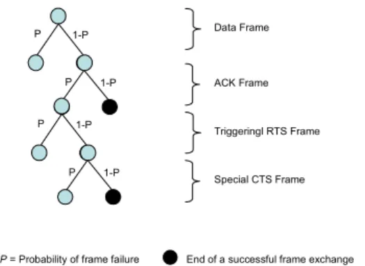
(2) (Fast Retransmit), or timeout occurs (Slow Start), the sender retransmits the corresponding TCP packet. On the other hand, retransmission in the link layer happens when the timer to receive an ACK expires. Compared with TCP retransmission, link layer retransmission adapts quickly to link characteristics due to shorter timeout periods. Moreover, since the length of a frame is much shorter than that of a TCP packet, retransmission in the link layer costs less than that in TCP. In the last five years many researchers have been focusing on improving TCP retransmissions to solve wireless TCP problems [6][7][9]. Balakrishnan (1995) proposed the snoop TCP scheme, a TCPaware link layer protocol using link layer retransmission from a base station [5]. Extensions of link layer retransmission are also used in research on QoS over wireless LANs [11]. Optimizing the retransmission scheme in the link layer achieves higher transmission efficiency than that in higher layers. However, no research has been done on link layer retransmission to improve the efficiency of the basic frame exchange protocol. In this paper we proposed an enhanced link layer retransmission scheme based on the 802.11 standard to make transmission more effective. III. DYNAMICALLY ADAPTIVE RETRANSMISSION. research proposes an enhanced scheme, called Dynamically Adaptive Retransmission (DAR) scheme, to avoid redundant retransmissions for high transmission efficiency. To illustrate the proposed scheme, a model based on the probability of frame losses is presented in Fig.1. Each node represents a transmission state and each directed edge represents a state transition. A value is assigned to show the probability of the transition on each edge. The initial state is at the top in Fig.1. If the directed edge goes southeast, it stands for a successful frame delivery. If the directed edge goes southwest, it indicates a frame delivery failure. The conventional two-way frame exchange protocol is studied as follows (Fig.1). We suppose that the probability of frame errors is a fixed value P, regardless of the frame type. Let F(e) be the probability of an event e. We have the following:. failure. success. P. Data Frame. 1-P. P. 1-P. ACK Frame. A. Background Knowledge The usage of the two-way and four-way frame exchange protocols are specifically defined in the IEEE 802.11 standard. A variable, called RTSThreshold as defined in the MIB (Message Information Base) of 802.11 standard, determines which type of frame exchange is used. When the frame size is less than the value of RTSThreshold, the two-way frame exchange will be utilized. Otherwise, the four-way frame exchange will take effect. ACK frame losses may occur in both the twoway and four-way frame exchanges, and yield redundant retransmission. That means the receiver may have received the data frame correctly, and the error may only have occurred in the reception of the ACK frame. To the sender of the frame exchange, this condition is indistinguishable from that in which an error occurs in the initial data frame. The sender may then simply retransmit the unacknowledged frame, which is redundant to the receiver. This. P = Probability of frame failure. End of a successful frame exchange. Fig.1 Scenarios of two-way frame exchange protocol.. The probability of a successful frame exchange in the 802.11 standard is represented as line 2 in Fig.2 where the X axis is probability of frame loss and the Y axis is the probability of a successful frame exchange. Line 1 in Fig.2 is an ideal target which means the probability of a successful frame exchange = 1 - (the probability of the frame loss). And our objective in proposing an enhanced scheme is to find a curve, represented as line 3 in Fig.2, which is closely approaching line 1 between the line 1 and line 2.. Fig.2 Probability of successful frame exchange..
(3) B. Dynamically Adaptive Retransmission (DAR) Scheme In order to avoid retransmission redundancy, the sender needs additional information to determine whether a retransmission is necessary. The two-way and four-way frame exchange protocols may be different in conveying the retransmission information because different frame types may be involved in the two protocols. Hence the DAR scheme consists of two parts of improvements and will be explained respectively in the following of this section. 1) Improved Two-Way Frame Exchange Protocol. The improved two-way frame exchange protocol for both the sender and the receiver are illustrated in Fig.3 and Fig.4.. As shown in Fig.4, the receiver will respond to the triggering data frame with a special ACK frame whose subtype is 0000 when the previous data has been successfully received. Otherwise a regular ACK frame will be sent back to the sender so that the sender is able to determine the previous data frame was lost and retransmission is necessary It is obvious that the triggering data frame and the special ACK frame with additional transmission information are helpful in determining whether a retransmission is necessary. Clearly the probability of a successful frame exchange improves as shown in Fig.5.. i=1;N=1 P. Send frame N Modified Parts. Receive ACK N ?. P. N = N +i i=1. Yes. P. No. Buffer frame N Set frame(N+i) subtype=1000 Send frame N+i No. Yes. 1-P. ACK Frame. 1-P. P. Triggering data Frame. 1-P. Special ACK Frame. i++. Receive ACK N+i ?. P = Probability of frame failure. Yes. N = N +i+1 i=1. Data Frame. 1-P. No. End of a successful frame exchange. Fig.5 Scenarios of the improved two-way frame exchange protocol.. Is frame N received? ACK N+i subtype==0000?. Fig.3 Improved two-way frame exchange protocol at the sender.. 2) Improved Four-Way Frame Exchange Protocol. In the two-way frame exchange protocol, as shown in Fig.3, after the sender sends a data frame, call it frame N, it buffers the frame in case it does not receive the corresponding ACK frame. The sender then sends the next data frame with subtype = 1000, called a triggering data frame, which triggers an inquiry from the sender to the receiver.. Different from the improved two-way frame exchange protocol, we use the existing RTS/CTS frame exchange to piggyback the transmission information to the sender in the improved four-way frame exchange protocol as shown in Fig.6 and Fig.7. N=1. Receive frame N= SN of the frame Frame N subtype == 1000?. Send frame N No Receive ACK N ?. Yes Was frame N-1 received?. Yes. N = N +1. No. No. Set RTS subtype=1000 Send RTS. Yes. Set ACK N subtype=0000. No. Yes. Send ACK N No. Fig.4 Improved two-way frame exchange protocol at the receiver.. Receive CTS ?. Is frame N received? Yes CTS subtype==0010?. Fig.6 Improved four-way frame exchange protocol at the sender..
(4) In the improved four-way frame exchange protocol, as shown in Fig.6, the frame exchange initiator sends a special RTS frame whose subtype is 0001, called a triggering RTS if it is unable to receive a positive ACK frame before the next transmission. Retransmission is not invoked immediately at this time. Receive frame N=SN of the frame. P. Data Frame. 1-P. P. P. ACK Frame. 1-P. 1-P. P. Triggeringl RTS Frame. 1-P. Special CTS Frame. No. RTS ?. P = Probability of frame failure. End of a successful frame exchange. Yes No. Subtype==0001?. 3) Frame Formats. Yes Frame N-1 received?. Fig.8 Scenarios of the improved four-way frame exchange protocol.. No. Yes. Set CTS subtype=0010 Send CTS Regular frame processing. Fig.7 Improved four-way frame exchange protocol at the receiver.. As shown in Fig.7, the sender knows that the previous data frame did not arrive at the receiver upon receipt of a regular CTS frame. Retransmission becomes necessary in this case. Otherwise, the sender just ignores the case of a lost ACK frame if it receives a special CTS frame whose subtype is 0010. If the last data frame is followed by an ACK loss, the sender will still initiate a triggering RTS inquiring whether the last data frame has been successfully delivered. In this RTS frame the duration field will be filled in accordance with the expected special CTS only. It can be seen that the sender does not need to buffer frames in this scheme because it will be capable of determining which frame to send before real transmission. Note that the 802.11 MAC layer semantics are not violated in this scheme because the frame exchange process is not intercepted and the frame exchange sequence remains the same, which means it is still atomic. Fig.8 show the scenarios of DAR.. Currently in the IEEE 802.11 standard [1], four frames (RTS, CTS, data and ACK) are used in a frame exchange process. Their formats are represented in Fig.9. The type and subtype values in the frame control field of a frame determine the type of the frame. In these fields there are some reserved values, not defined in the current standard. Four special frames required in support of DAR use the reserved values (shown as an example in Table 1) to convey additional information on the transmission status.. Fig.9 MAC frame format and control field. Table 1 New frame types and subtypes Frame. Type. Subtype. Data. 10. 1000. ACK. 01. 0000. RTS. 01. 0001. CTS. 01. 0010. 4) Benefits of DAR. It is worthy to note that the DAR scheme does not require new frame formats, but uses the reserved values of the subtype filed in the 802.11 standard. No extra cost on the bandwidth will be wasted because the DAR scheme does not utilize additional frames in.
(5) the frame exchange. Informative bits in the specially defined frames in the DAR scheme convey the transmission condition with which the transmission initiator can wisely determine whether to retransmit or not. Thus great benefits will be achieved when redundant retransmissions can be avoided.. When the bit error rate is relatively low, the differentiation ratio is high, which means many failure cases can be differentiated by the improved protocol as ACK loss cases without invoking retransmission. This gives a desirable result. 1 0.9. IV. THEORETICAL ANALYSIS. 0.8 0.7 Differentiation ratio. To demonstrate the benefits of DAR, Fig.10 shows the performance improvement (represented as the probability of successful frame exchange on the Y axis) with respect to bit error rate (represented as BER on the X axis).. 0.6 0.5 b 0.4 0.3 0.2 0.1. 0.84 0 0. Prob. of Successful Frame Exchange. 0.00001. 0.00002. 0.00003. 0.00004. 0.00005. BER. 802.11 2-way. Fig.11 Differentiation ratio in the improved two-way frame exchange protocol.. 0.83. V. EXPERIMENTS A. Experimental Methodologies. 0.82. 0.81 0.000009. 0.0000091. 0.0000092. 0.0000093. 0.0000094. 0.0000095. 9.6E-06. 9.7E-06. 9.8E-06. 9.9E-06. 1E-05. BER. Fig.10 Performance improvement in the DAR scheme.. Obviously the probability of successful frame exchange in the enhanced scheme is higher than that in the current IEEE 802.11 standard. Performance will be improved as a result. An important concept in the analysis is the differentiation ratio, defined to measure the performance of DAR. We define the differentiation ratio as the ratio of successfully delivered frames with lost ACKs that can be differentiated by the sender using the enhanced scheme over all failed frames detected by the conventional retransmission scheme. It is obvious that the differentiation ratio in the conventional 802.11 frame exchange protocol is always 0. An example of the differentiation ratio in the improved two-way frame exchange protocol is shown as fellows.. where p represents BER, and lend and lena represent the lengths of the data and ACK frames. Fig.11 shows the differentiation ratio in the improved twoway frame exchange protocol with respect to BER.. We developed a simulator in C to determine the performance and efficiency of the proposed DAR scheme. The MAC layer basically follows the IEEE 802.11 standard [1]. The DAR protocol is implemented as a set of modifications to the frame exchange protocol in the MAC layer. Our experimental testbed consists of two mobile hosts, which are interconnected using a shared-medium wireless LAN with a raw signaling bandwidth of 2 Mbps. This is because we attempt to ensure that losses are due only to wireless errors, not congestion. This also allows us to focus on the effectiveness of the mechanisms for handling such losses. The simple testbed topology represents typical scenarios for wireless links and mobile hosts, such as cellular wireless networks. In addition, our experiments focus on MAC frame exchange between the mobile hosts. In order to measure the performance of the protocols under controlled conditions, we generate errors on the lossy link using a uniformly distributed bit-error model. Each run in the experiment consists of a 10 MByte transfer from the sender to the receiver across the wireless link. We chose this rather long transfer size in order to limit the impact of transient behavior. During each run, we measure the goodput as normalized between 0 and 1. The other parameters in the simulation models, listed in the Table 2 and 3, are referenced from [13]..
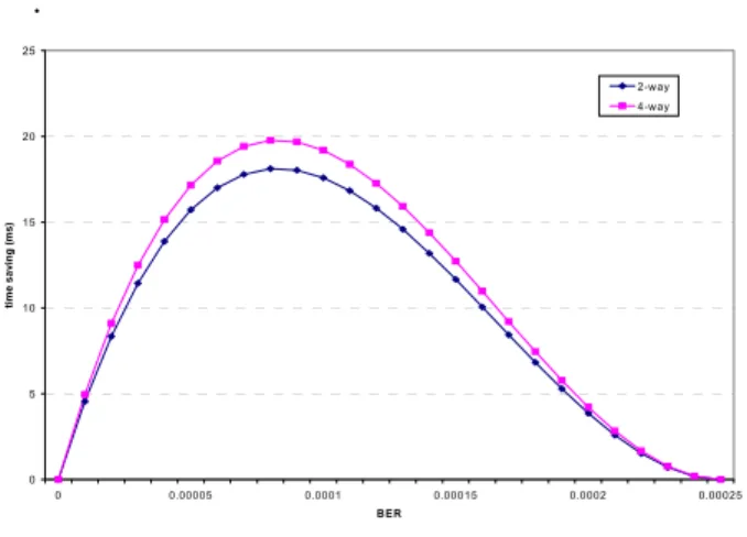
(6) . Table 2 Parameters in the experiments. 25 2-way 4-way. Transfer Time. Frame. Size (Byte). Data. 500 (4-way) 300 (2-way). 4292 2575. ACK. 14. 120. RTS. 20. 144. CTS. 14. 20. time saving (ms). ( µs ). 15. 10. 120. RTSThreshold. 400. 5. Table 3 Parameters in the experiments (cont'd). 0 0. 0.00005. 0.0001. 0.00015. 0.0002. 0.00025. BER. Duration. Interframe space. Fig.13 Time savings in the DAR scheme.. ( µs ). SIFS. VI. FURTHER DISCUSSION. 10. DIFS. 110. ACK timeout. 120. We use goodput to measure the performance of both DAR and the 802.11 standard. The concept of goodput of the link layer is taken from TCP and defined as the bandwidth delivered to the receiver through the link excluding duplicate frames. Thus, the goodput Gl of a link l during a time interval t corresponds to the number of bytes B of link l forwarded to the upper layer during the interval t [5]. B. Experiment Results Fig.12 shows the goodputs in 802.11 vs. the improved four-way frame exchange protocol with respect to BER. DAR achieves higher goodput than the 802.11 standard. To demonstrate the benefit of DAR scheme we calculated the time savings using the BER loss rate as shown in Fig.13. The improved four-way frame exchange protocol saves more time expenditures on RTS and CTS frames in addition to data frames. 1. 0.9. 0.54. 0.8. 0.52. 0.7. 802.11 0.5. DAR. Goodput. 0.6. 0.48 0.000024. 0.5. 0.4. 0.3. 0.2. 0.1. 0 0. 0.00001. 0.00002. 0.00003. 0.00004. 0.00005. BER. Fig.12 Goodput in the improved four-way vs. 802.11 with respect to BER.. As mentioned in section III., to recover from the frame loss, a data buffer is needed at the sender for the unacknowledged frame. It is obvious that more buffers may handle more complex cases such as consecutive ACK or CTS losses. However, it might be impractical to allocate a huge amount of buffer for each transmission due to limitations on memory resources. Moreover, the probability of the above event can be low. Experiments to explore the amount of buffer needed for each transmission therefore are necessary. Theoretically the number of buffers determines the number of consecutive response losses that can be handled, because the unacknowledged data frames can be buffered before the sender receives either affirmative or negative confirmation from the receiver. Fig.14 shows the probability of consecutive response losses in various BER situations. The X axis represents the number of consecutive response losses including ACK and CTS frame losses. The Y axis represents the probability of these occurrences. Three lines have been drawn based on three different bit error rates, 0.001, 0.01 and 0.1. It can be seen that the more consecutive lost responses considered, the lower the probability. The lower the bit error rate, the more quickly the possibility degrades. Considering practical situations where the BER is low, it is unnecessary to cope with more than two consecutively lost responses as proposed in our DAR scheme..
(7) 0.1 BER=0.001. 0.001. BER=0.01. 1E-05. BER=0.1. 1E-07. Prob. of Occurrences. 1E-09 1E-11 1E-13 1E-15 1E-17 1E-19 1E-21 1E-23 1E-25 1E-27 1E-29 1E-31 1. 2. 3. 4. 5. 6. 7. 8. 9. 10. Number of Consecutive Reponse Loss. Fig.14 Probability of consecutive response losses in various BERs.. VII. CONCLUSIONS The current IEEE 802.11 standard confuses the sender when a positive ACK is lost during its way back. The sender will take it as an unsuccessful delivery and simply retransmit the data frame. An enhanced DAR scheme is introduced in our paper, proposing a new feedback scheme, in which the CTS frames carry additional information concerning the previous data delivery without violating the 802.11 MAC layer semantics. Our method proves to be efficient in handling such error conditions as stated in the paper. Experiments and analysis show that the DAR scheme efficiently decreases redundant retransmission by clearly differentiating ACK frame losses. REFERENCES [1] "Wireless LAN Medium Access Control (MAC) and Physical Layer (PHY) Specifications," IEEE 802.11 standard, 1997. [2] B. O'Hara and A. Petrick, IEEE 802.11 handbook. A designer's companion, IEEE Press, 1999. [3] B. P. Crow, I. Widjaja, J. G. Kim, P. T. Sakai, "IEEE 802.11 wireless local area networks," IEEE Communication magazine, Sep 1997. [4] J. Weinmiller, H. Woesner, J. P. Ebert, A. Wolisz, "Analyzing the RTS/CTS mechanism in the DFWMAC media access protocol for wireless LANs," IFIP TC6, 1995. [5] H. Balakrishnan, S. Seshan, E. Amir, R. H. Katz, "Improving TCP/IP performance over lossy networks," Proc. of the first ACM International Conference on Mobile Computing and Networking, Nov 1995. [6] H. Balakrishnam, V. N. Padmanabhan, S. Seshan, R. H. Katz, "A comparison of mechanisms for improving TCP performance over lossy links," IEEE/ACM. Transactions on Networking, Dec 1997. [7] M. Mathis, J. Mahdavi, S. Floyd, A. Romanow, "TCP selective acknowledgement (SACK) options," RFC 2018, Oct 1996. [8] K. Fall and S. Floyd, "Simulation-based comparisons of Tahoe, Reno, and SACK TCP," Computer Communication Review, July 1996. [9] M. Mathis and J. Mahdavi, "Forward Acknowledgement: refining TCP congestion control," ACM SIGCOMM, 1996. [10] H. Balakrishnan and R. H. Katz, "Explicit loss notification and wireless web performance," Proc. of IEEE Global Telecommunications Conference (GLOBECOM), Mini Conference, Nov 1998. [11] C. F. Chiasserini and M. Meo, "Improving TCP over wireless through adaptive link layer setting", Proc. of IEEE Global Telecommunications Conference (GLOBECOM), 2001 [12] W. Ding and A. Jamalipour, "A new explicit loss notification with acknowledgment for wireless TCP," Proc. of 12th IEEE International Symposium on Personal, Indoor and Mobile Radio Communications , Sept. 2001. [13] S.-T. Sheu, T.-F. Sheu, C.-C. Wu, J.-Y. Luo, "Design and implementation of a reservation-based MAC protocol for voice/data over IEEE 802.11 ad-hoc wireless networks," Proc. of IEEE International Conference on Communications (ICC), 2001.
(8)
數據
相關文件
Courtesy: Ned Wright’s Cosmology Page Burles, Nolette & Turner, 1999?. Total Mass Density
Theorem 5.6.1 The qd-algorithm converges for irreducible, symmetric positive definite tridiagonal matrices.. It is necessary to show that q i are in
A socket is a file descriptor that lets an application read/write data from/to the network. Once configured the
This painting inspired me to explore personal styles for my self-portrait, or the characteristics that represent myself in my work, so that people will feel the work is unique and
* All rights reserved, Tei-Wei Kuo, National Taiwan University, 2005..
The remaining positions contain //the rest of the original array elements //the rest of the original array elements.
The PLCP Header is always transmitted at 1 Mbit/s and contains Logical information used by the PHY Layer to decode the frame. It
If sender receives 3 ACKs for the same data, it supposes that segment after ACKed data was lost:. fast retransmit: resend segment before timer
