Optically Injection Mode-Locked 1.3
µµµµ
m Semiconductor Optical
Amplifier Fiber Ring Laser by Using Gain-Switching Single-Mode
FPLD
Pai-Shen Hsueh
*, Shih-Kai Lee, and Gong-Ru Lin
1Institute of Electro-Optical Engineering, National Chiao Tung University
*
Graduate Institute of Opto-Electronic Technology, National Taipei University of Technology
ABSTRACT
We demonstrate a novel approach for generating a stable and low polarization-sensitive mode-locked fiber ring laser by using a low-cost Fabry-Perot laser diode (FPLD) as both the intracavity mode-locker and the band-pass filter. The FPLD pulses is seeded into a close-loop semiconductor optical amplifier (SOA) based fiber ring laser for harmonic
and rational harmonic mode-locking operation. The SOA biased at 65 mA and 18oC combines with an intracavity
optically feedback-injected 1.3 µm FPLD biased at 9.4 mA (below threshold current) and 23oC via some optical
couplers. Picosecond optical pulse with side-mode suppressing ratio of greater than 12 dB are obtained, the measured lindwidth at 3-dB and 10-dB decay are observed to maintain at about 0.04 nm and 0.14 nm, respectively. Narrow-linewidth operation of the SOAFL with optical pulsewidth of 42.1 ps and wavelength tuning range of about 10 nm at repetition rate of 13 GHz has been demonstrated. The optically injection mode-locking scheme also has shown to exhibit low supermode noise, higher average output power and good stability. The optical output power under
harmonic mode-locked scheme is about 297 µW. The fluctuation in output power, the SSB phase noise at 1 kHz offset
frequency, and the calculated rms timing jitter within the integral region from 0 Hz to 1 KHz are ̈́ 2.5 µW, -82.4
dBc/Hz, and 1.0 ps, respectively.
Keywords: Semiconductor optical amplifier, fiber ring laser, optically injection mode-locked, harmonically
mode-locked, single-mode FPLD, self-seeding
1. INTRODUCTION
Pulsed fiber optical sources with pulsewidth of some picoseconds and GHz repetition frequencies are of great interest in particular for the development of high speed optical communication systems. For experimental systems to be installed in the laboratory, the required sources are with wide tunability of wavelength, pulse width and repetition rate. By modelocking an Er-doped fiber ring laser, ultrashort optical pulses of 280 fs duration at repetition rate of 10 GHz has been generated. This requires harmonic mode-locking (up to several hundreds to thousands) at GHz pulse repetition rates due to the long cavity length. In addition, most of these devices are either not tunable or strictly tunable in wavelength and repetition rate. The sophisticated and extensive setup for aforementioned requirements is necessary. Mode-locked semiconductor amplifier based lasers are possible candidates for optical carriers in high-speed optical communication systems. It is known that harmonically mode-locking technology is one of the most intriguing methods for generating pulses with high repetition rate. At frequencies of several tens of gigahertz, the low cost of electronics signal sources make optical techniques attractive for generating high repetition-rate optical pulses. Different approaches include multiplying the repetition-rate of a lower frequency optical pulse-train [1-3] or high-order mode-locking of a fiber ring laser [4, 5]. However, most of wavelength tunable short pulse generation techniques have used active mode locking of an erbium doped fiber ring laser with lithium niobate modulator and wavelength tunable
Corresponding E-mail: [email protected]; Phone: 886 3 5712121 ext. 56376; Fax: 886 3 5716631; Address: Institute of
filter.
Recently, a semiconductor fiber ring laser using a semiconductor optical amplifier (SOA) has been attracted research interest due to its broad wavelength-tuning range, high stability, narrow linewidth, single-mode output capatibility, etc. [6-9] Various cavity configurations have recently been demonstrated to implement high-repetition-rate wavelength-tunable SOAFL. In particular, the generation of a tunable 40 GHz optical pulse-train from a fiber ring laser with a semiconductor optical amplifier has been developed by using 10 GHz electronics and optical repetition-rate multiplication. The wavelength of the 40 GHz pulse-train with pulsewidth of ~ 8 ps can be tuned by a tunable fiber Fabry-Perot (FFP) filter in the ring over a wavelength range of 20 nm [10]. Different approach has also been achieved by using a 5 GHz DFB laser as seeding optical source [11]. However, these schemes are more complicated and not cost-effective. In this letter, we demonstrate a simple technique for generating a narrow-linewidth 13 GHz pulse-train from a SOA-based fiber ring laser system using frequency-multiplied 1 GHz pulses, and we report a systematic study of the key parameters of this system. Unlike previous work, the single-mode SOAFL ring cavity operation with high repetition rate can be achieved without using any components such as optical circulator, fiber Bragg grating, DBR or DFB master laser diodes, and optical bandpass filter. The FPLD acts as both a intracavity mode-locker and a band-pass filter for generation a stable and low polarization-sensitive pulse-train. Such a laser scheme exhibits low supermode noise, stable average output power and fairly good stability.
2. EXPERIMENTAL SETUP
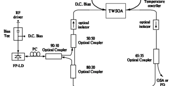
The experimental setup of the rational harmonic mode-locked SOAFL is shown in Fig 3, which consists of a
travelling-wave typed SOA, a 1.3-µm commercial fiber-pigtailed FPLD, an in-line polarization controller, and four
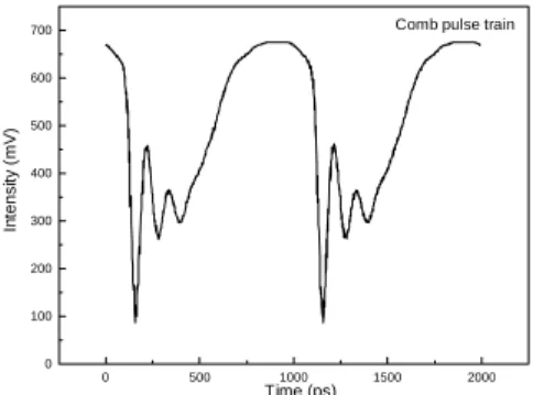
optical couplers with various power splitting ratios. The gain-switching system for FPLD is constructed by using a RF synthesizer (HP 8648A) in connection with a 24 dB power amplifier and a comb generator (HP 33004A) for 42 ps electrical pulse generation. In addition, a DC current source is employed to offset the driven level of FPLD via a Biased-Tee circuit. This helps generating optical pulses with full-width-at-half-maximum of ranging from 20 to 30 ps at different frequencies, as shown in Fig. 1. The gain-switched PFLD is employed as an optically injection comb generator with pulsewidth of 124.42 ps, which seeds into the SOAFL for pulsed gain modulation. The RF signal generated from a frequency synthesizer (HP8648A) at 1 GHz is used to activate an electrical pulse former (i.e. comb generator, HP 33005C). As can be seen from Fig. 2, the electrical pulsewidth is much wider than the generated gain-switched FPLD pulsewidth. In this case, the harmonic mode-locking at repetition frequency of 1 GHz or rational harmonic mode-locking with repetition rate up to 13 GHz can be easily observed from the EDFL synchronously pumped by the intracavity Feedback-injected FPLD.
0 500 1000 1500 2000 -1 0 1 2 3
4 Gain-switch pulse train
In te n s it y ( m V ) Time (ps)
Fig. 1 The sampled pulse shape of a gain-switched FPLD output. 0 500 1000 1500 2000 0 100 200 300 400 500 600
700 Comb pulse train
In tens it y ( m V ) Time (ps)
Fig. 2 The electrical pulse shape of the comb generator.
In experiment, the FPLD with mode spacing of 0.75 nm is biased at 9.4 mA (below the threshold current of Ith = 12
mA). The output of the FPLD is coupled through an in-line polarization controller(PC) into the close-loop SOAFL
ring cavity via a single mode fiber coupler with ratio of 90:10. The in-line PC is mandatory for fine adjusting the polarization state of the light feedback-seeding the FPLD, which has be carefully align to match the eigenstates of
FPLD and therefore guarantee the single-mode oscillation, optimize and suppress the intensity noise of both FPLD and SOAFL. The 90 % coupling ratio of the 90:10 coupler is connected to SOAFL with a 50:50 coupler and the other 10 % coupling ratio of the coupler feedback the SOAFL light into the FPLD light with a 80:20 coupler with 20 % coupling ratio. These optical couplers, in the main, couple the output of gain-switched FPLD into SOAFL and feedback part of the SOAFL output into the gain-switched FPLD. The output information is coupled from the SOAFL via another optical coupler, which coupled 65 % of the output power of the fiber ring. The chose of a 65 % output maintained a relatively low power circulating inside the fiber ring and increased the sensitivity of the SOA to the high repetition rate injected signal. An optical spectrum analyser with a 0.01 nm resolution (Advantest, Q8384) was used to view the spectral characteristics, and an optical power meter (ILX Lightwave, OMM-6810B) was used to measure the output power of the SOAFL when we tuned at different current and temperatures. The pulsewidth and pulse amplitude of
SOAFL are monitored by a high-speed photodetector (New Focus 1014, f3dB > 45 GHz) and a digital sampling
oscilloscope (HP 54750A, f3dB > 50 GHz). The SSB phase noises of the input GSLD and output injection SOAFL
were determined by using a 40GHz microwave spectrum analyzer (ROHDE & SCHWARZ FSEK 30) with resolution
bandwidth of 1 Hz. ˙˙˙˙ˣˣˣˣˀˀˀˀ˟˟˟˟˗˗˗˗ ˣˣˣˣ˖˖˖˖ ̂̂̂̂̃̃̃̃̇̇̇̇˼˼˼˼˶˶˶˶˴˴˴˴˿˿˿˿ ˼˼˼˼̆̆̆̆̂̂̂̂˿˿˿˿˴˴˴˴̇̇̇̇̂̂̂̂̅̅̅̅ ˉˉˉˉˈˈˈˈˍˍˍˍˆˆˆˆˈˈˈˈ ˢ ˢ ˢ ˢ̃̃̃̃̇̇̇̇˼˼˼˼˶˶˶˶˴˴˴˴˿˿˿˿ʳʳʳʳ˖˖˖˖̂̂̂̂̈̈̈̈̃̃̃̃˿˿˿˿˸˸˸˸̅̅̅̅ ˧ ˧˧ ˧˪˪˪˦˦˦˦ˢ˪ˢˢ˔ˢ˔˔˔ ̂̂̂̂̃̃̃̃̇̇̇̇˼˼˼˼˶˶˶˶˴˴˴˴˿˿˿˿ ˼˼˼˼̆̆̆̆̂̂̂̂˿˿˿˿˴˴˴˴̇̇̇̇̂̂̂̂̅̅̅̅ ˗ ˗ ˗ ˗ˁˁˁˁ˖˖˖˖ˁˁˁˁʳʳʳʳ˕˕˕˕˼˼˼˼˴˴˴˴̆̆̆̆ ˧˧˧˧˸˸˸˸̀̀̀̃̃̃̃˸˸˸˸̅̅̅̅˴˴˴˴̇̇̇̇̈̈̈̈̅̅̅̅˸˸˸˸˶˶˶˶̂̂̂̂́́́́̇̇̇̇̅̅̅̅˿˿˿˿˿˿˿˿˸˸˸˸̅̅̅̅̀ ˈˈˈˈ˃˃˃˃ˍˍˍˍˈˈˈˈ˃˃˃˃ ˢ ˢ ˢ ˢ̃̃̃̃̇̇̇̇˼˼˼˼˶˶˶˶˴˴˴˴˿˿˿˿ʳʳʳʳ˖˖˖˖̂̂̂̂̈̈̈̈̃̃̃̃˿˿˿˿˸˸˸˸̅̅̅̅ ˢ ˢˢ ˢ˦˦˦˦˔˔˔ʳʳʳʳ̂̂̂̂̅̅̅̅˔ ˣˣˣˣ˗˗˗˗ ˋˋˋˋ˃˃˃˃ˍˍˍˍ˅˅˅˅˃˃˃˃ ˢ ˢ ˢ ˢ̃̃̃̃̇̇̇̇˼˼˼˼˶˶˶˶˴˴˴˴˿˿˿˿ʳʳʳʳ˖˖˖˖̂̂̂̂̈̈̈̈̃̃̃̃˿˿˿˿˸˸˸˸̅̅̅̅ ˌˌˌˌ˃˃˃˃ˍˍˍˍ˄˄˄˄˃˃˃˃ ˢ ˢ ˢ ˢ̃̃̃̃̇̇̇̇˼˼˼˼˶˶˶˶˴˴˴˴˿˿˿˿ʳʳʳʳ˖˖˖˖̂̂̂̂̈̈̈̈̃̃̃̃˿˿˿˿˸˸˸˸̅̅̅̅ ˕ ˕˕ ˕˼˼˼˼˴˴˴˴̆̆̆̆ ˧ ˧˧ ˧˸˸˸˸˸˸˸˸ ˥ ˥ ˥ ˥˙˙˙˙ ˷˷˷˷̅̅̅̅˼˼˼˼̉̉̉̉˸˸˸˸̅̅̅̅ ˗ ˗˗ ˗ˁˁˁˁ˖˖˖ˁˁˁˁʳʳʳʳ˕˖˕˕˕˼˼˼˼˴˴˴˴̆̆̆̆
Fig. 3 The experimental setup for generating 13 GHz pulse-train
3. RESULTS AND DISCUSSION
At repetition frequency of gain-switched FPLD equivalent to fm≅ 1 GHz, the optical pulse-trains of the SOAFL
operated at from fundamental to 13th rational harmonic mode-locking conditions by use of the FPLD as both an
intracavity mode-locker and band-pass filter are shown in Fig. 4. The temporal traces of the mode-locked SOAFL in Fig. 4 illustrates the traces for different harmonic mode-locking orders with (a) n = 57 and p= 2; (b) n = 64 and p = 4; (c) n = 71 and p = 10; and (d) n = 70 and p =13. The highest rational harmonic mode-locking of the SOAFL at repetition rate of 13 GHz obtain such a synchronous pumping condition is shown in Fig. 4(d). The perfect mode-locked pulses can only be observed when the modulation frequency is exactly an integral multiple of the cavity longitudinal mode
spacing. The shortest and stable optical pulses can be obtained by careful tuning of the modulation frequency fm and
the polarization of the circulating light through the polarization controller. The pulsewidth of 42.1 ps of mode-locked SOAFL pulses trains at repetition rate of 13 GHz is measured by sampling oscilloscope. Under a higher gain condition of SOA, further improvement in the repetition rate can be expected by exciting higher order rational harmonic modes. Figure 5 shows the corresponding RF spectra of rational harmonic mode-locked pulses. The phenomenon of
rational harmonic mode locking is observed when the modulation frequency fm=(n+1/p)fc, where n and p are integers.
It was observed that the fundamental cavity frequency fc was 13.9 MHz and these traces corresponded to the harmonic
orders of n ranging from 57 to 71. A 13-GHz pulse train is observed when fm=(70+1/13)fc. Although there is some
signal at the modulation frequency fm, the peak component always appears at the frequency pfm, which is the repetition
rate of the pulses train due to rational harmonic mode locking [12]. The generation of optical pulses with higher repetition rate using the rational harmonic mode-locked technique may be possible.
The lasing modes of the proposed SOAFL source are controlled by both the gain profiles of SOA and FPLD in Fig. 6. Such a scheme successfully links the amplification characteristic of a SOA ring cavity, and the mode-selecting capability of the FPLD. To obtain stable pulses with high repetition rate at the worst gain modulation (or synchronous pumping) condition, a sinusoidal electrical signal with power of 0 dBm is employed to gain-switch the FPLD. In this case, single FPLD longitudinal mode operation is achieved, which leads to the generation of SOAFL pulses with
FWHM of 42.1 ps. A broad wavelength tuning range of up to 10 nm for the rational harmonic mode-locked SOAFL with repetition rate of 13 GHz has been obtained via the synchrouous pumping by gain-switched single-mode FPLD.
Harmonic and Rational Harmonic Mode Locked IDC.SOA= 65 mA TSOA = 18 oC I LD = 9.4 mA TLD = 23 oC In te n s it y ( 1 6 m V /d iv ) Offset = 4 m V Time (ns) 0.0 0.5 1.0 1.5 2.0
Fig. 4: Generation of pulse trains using rational harmonic
mode locking around fm ~ 1 GHz at different repetition rate.
In te ns it y (5 0 dB m/ di v ) R e f Lv l = -2 0 d B m Frequency from 0 Hz to 40 GHz
Fig. 5: RF spectra at different order rational harmonic mode
locking for fm ~ 1 GHz.
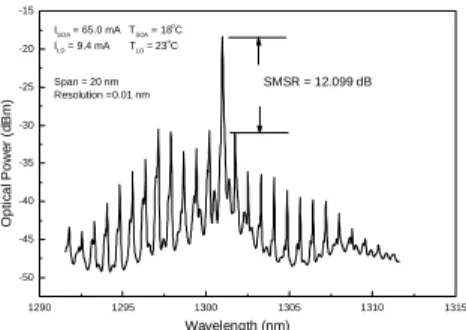
The best operating condition of the SOAFL is observed as the SOA biased at 65 mA and 18 к and the intracavity
optically feedback-injected 1.3 µm FPLD biased at 9.4 mA (below threshold current) and 23 к. Note that the
threshold current of the SOAFL at 18 к and FPLD at 23 к is about 40 mA and 12 mA, respectively. Side-mode
suppressing ratio of higher than 12 dB are obtained with measured linewidth at 3-dB and 10-dB decay of about0.04 nm
and 0.14 nm, respectively. 1290 1295 1300 1305 1310 1315 -50 -45 -40 -35 -30 -25 -20 -15 ISOA = 65.0 mA TSOA = 18 oC ILD = 9.4 mA TLD = 23 oC Span = 20 nm Resolution =0.01 nm SMSR = 12.099 dB O p ti c a l P o w e r (d B m ) Wavelength (nm)
Fig. 6: Mode-locked output pulse generation from SOA fiber ring laser with optical spectrum.
The variations of the peak power at different repetition rates are plotted in Fig. 7. The input pumping power is
about 2.5 µW and the fiber output power is about 297 µW with fundamental mode-locked. The fluctuation in output
power variance is within ̈́ 2.5 µW or 0.54 percent. The peak power of the SOAFL is found to increase as the rational
harmonic mode-locking order increases. However, both the polarization fluctuation in the long fiber cavity due to mechanical vibrations and the cavity length drift due to fluctuations in the temperature of the SOA or external environment can seriously degrade or interrupt the mode-locking process. In addition, the independent supermodes with their frequencies of equivalent to any integral multiples of the cavity fundamental frequency can simultaneously oscillate and compete with each other, which also lead to a strong fluctuation of the pulse amplitude. This is attributed as one of the principal noise sources in harmonic mode-locked fiber laser sources. Nonetheless, we also show in Fig. 8 that using a semiconductor optical amplifier in the cavity improves the stability of the fiber laser by suppressing the supermode noise. It is confirmed that the reduction of the supermodes in the RF spectrum by the SOAFL contributes to stable optical pulse generation in rational harmonic mode-locking conditions.
0 100 200 300 400 500 600 700 280 285 290 295 300 305 310 315 320 325 330 335 340 345 350 Repetition rate = 10 GHz ( fm = 984.20541 MHz ) Repetition rate = 13 GHz ( fm = 977.28607 MHz )
Fundamental Mode Locked ( fm = 797.74454 MHz ) ISOA = 65.0 mA TSOA = 18 o C ILD = 9.4 mA TLD = 23 o C Power Stability Pow e r ( µ W) Time (Sec)
Fig. 7 The peak powers of SOAFL at different repetition rates
Peak Power = -55.54 dBm Span = 100 MHz Center Frequency = 12.7047 GHz Po we r ( 5 d B m /d iv ) Frequency (Hz)
Fig. 8 The output power spectrum of SOAFL at repetition rate of 13 GHz.
The phase noise of the detected RF signal and timing jitter are two important parameters in evaluating the performance of this technique. Fig. 9 show a representative phase noise spectrum of the fundamental harmonic in the
periodic orbit for 1 Hz to 10 kHz offsets from the center frequency. The SSB phase noise at 1 kHz is about -82.39
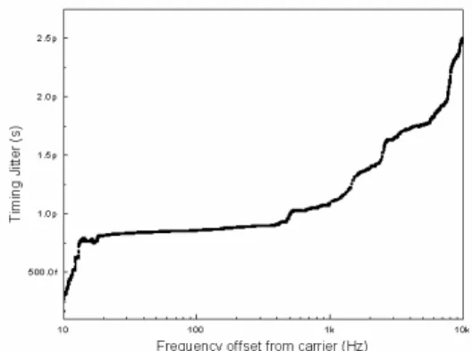
dBc/Hz. These results are consistent with the observed RF spectrum. Fig. 10 shows the measured phase noise of the detected 1 GHz signal and timing jitter of the generated optical pulse train as a function of frequency detuning, with an
injected optical power of 2.5 µW. The rms. Timing jitter σ(f) of the optical pulse can be calculated from the phase
noise-density spectrum of optical pulse, that can be described by
( )
{
[
(
( ) ( ))
(
)
]
}
12 2 10 / 10 / 0 1 / 10 10 2 2 1 1∫
− − = H L n f f f L f L df n f f π σ ,where n is the order of the harmonics being measure, f0 is the repetition rate of the optical pulse. The L1(f) and Ln(f)
are the noise power spectral density as a function of offset frequency measured at fundamental and nth harmonics,
respectively. The integral region from fL to fH is usually set as fL = 0 Hz and fH = 1 kHz. As show, in a frequency
range of 1 kHz, the rms timing jitter is calculated to be 1.0 ps in the integral region from 0 Hz to 1 kHz.
100 1k 10k -100 -90 -80 -70 -60 -50
-40 Fundamental Harmonic Mode-Locked
2 GHz 1 GHz P h as e N o is e (d B c /d iv ) Frequency (Hz)
ig. 9 The phase noise of the fundamental mode locked output ptical pulse train
Fig. 10 The timing jitter of the fundamental mode-locked output optical pulse train
4. CONCLUSION
In conclusion, we investigated in detail the characterization of rational harmonic mode-locked SOAFL induced by gain-witched FPLD injection. We have successfully demonstrated a new technique for generating a stable, low polarization-sensitive, low cost, mode-locked fiber ring laser by using a FPLD as both an intracavity mode-locker and band-pass filter. We also report a systematic study of the key parameters of this system. Side-mode suppressing
to maintain at about 0.04 nm and 0.14 nm, respectively. The input pump power is about 2.5 µW and the fiber output
power is about 297 µW with fundamental mode-locked. The value of the output power variance is ̈́ 2.5 µW which is
about 0.54 percent. The calculated timing jitters are about 1.0 ps and 2.5 ps within integral frequency ranges of 1 kHz and 10 kHz, respectively.
5. ACKNOWLEDGEMENTS
This work was supported in part by National Science Council (NSC) of the Republic of China under grants NSC89-2215-E-027-007 and NSC90-2215-E-027-008. The author would like to the thank Chung-Hwa Telecom Laboratories for loan of semiconductor optical amplifier and technical support.
6. REFERENCES
1. K. S. Abedin, N. Onodera, and M. Hyodo, “Repetition-rate multiplication in actively mode-locked fibre lasers by
higher-order FM mode locking using a high-finesse Fabry-Perot filter,” Appl. Phys. Lett. 10, pp. 1311-1313, 1998.
2. T. Papakyriakopoulos, K. Vlachos, A. Hatziefemidis, and H. Avramopoulos, “Optical clock repetition-rate
multiplier for high-speed digital optical logic circuits,” Opt. Lett. 11, pp. 717-719, 1999.
3. S. Arahira, S. Kutsuzawa, Y. Matsui, D. Kunimatsu, and Y. Ogawa, “Generation of synchronized subharmonic
synchronous mode-locked semiconductor laser diode using fiber dispersion,” IEEE Photon. Technol. Lett. 10, pp. 209-211, 1998.
4. C. Wu and N. K. Dutta, “High-repetition-rate optical pulse generation using a rational harmonic mode-locked fiber
laser,” IEEE J. Quantum Electron. 36, pp. 145-150, 2000.
5. K. S. Ahedin, N. Onodera, and M. Hyodo, “Generation of a 64GHz, 3.3ps transform-limited using a fibre laser
employing higher-order frequency-modulated mode locking,” Opt. Lett. 24, pp. 1564-1566, 1999.
6. D. H. Kim, S. H. Kim, Y. M. Jhon, S. Y. Ko, J. C. Jo, and S. S. Choi, “Relaxation-free harmonically mode-locked
semiconductor-fiber ring laser,” IEEE Photon. Technol. Lett. 11, pp. 521-523, 1999.
7. G. Lu, S. A. Boothroyd, and J. Chrostowski, “Tunable wavelength conversion in a semiconductor-fiber ring laser,”
IEEE Photon. Technol. Lett., 11, pp. 806-808, 1999
8. K. Vlachos, G. Theophilopoulos, A. Hat-zeifremidis, and H. Avamopoulos, Proc. of OFC2000, pp. 223-225, 2000
9. T. Papakyriakopoulos, K. Vlachos, A. Hatziefremidis, and H. Avramopoulos, Proc. of CLEO’99, pp. 121-122,
1999
10. M. W. K. Mak, H. K. Tsang and H. F. Liu, “Wavelength-tunable 40 GHz pulse-train generation using 10 GHz
gain-switched Fabry-Perot laser and semiconductor optical amplifier,” Electron. Lett. 36, pp. 1580-1581, 2000.
11. K. Zoiros, K. Vlachos, T. Stathopoulos, C. Bintjas, and H. Avramopoulos, “40 GHz mode-locked SOA fiber ring
laser with 20 nm tuning range,” Proc. of Opt. Fiber Comm. Conf. 1, pp. 254-256, 2000.
12. C. Wu and N. K. Dutta, “High-rapetition-rate optical pulse generation using a rational harmonic modelocked fiber