IEEE TRANSACTIONS ON ANTENNAS AND PROPAGATION, VOL. 52, NO. 1, JANUARY 2004 115
A Low-Cost Electrical Beam Tilting Base Station
Antennas for Wireless Communication System
Ruey Bing Hwang, Member, IEEE, Yin Jung Chang, and Ming-Iu Lai
Abstract—A multifunctional feeding network is presented in this paper. It contains a one-to-eight Wilkinson-based power di-vider and eight microstrip lines backed with slot array. In addition, the moveable card printed with seven metal strips servs as a novel phase shifter. By dynamically moving the card, we can adjust the number and shielding area of the slot array and then alter the dis-tribution of phase angle at each port of the feeding network accord-ingly. For example, in our application, we can have a progressive phase difference between the ports of feeding network and dynam-ically adjust them by changing the degree of perturbation on the slots array. The characteristic of beam tilting has been carefully ex-amined by measuring the phase angle at each port and also by the far-field radiation pattern of the patch antenna array integrated with this novel phase shifter, in various perturbation conditions. The reliable, easily fabricated, and low-cost characteristics show its potential applications in the base-station antenna design.
Index Terms—Array antennas, low-cost electrical beam tilting, perturbation, phase shifter.
I. INTRODUCTION
T
O REDUCE the interferences between two fre-quency-reuse cells and to improve the system per-formance against multipath distortion, antenna beams are tilted downward below the horizon to confine transmitted signal to each cell. Reviewing earlier literature concerning this topic, we found that various methods were developed to tilt the beam pattern of array antennas, such as mechanical [1], electrical [2]–[18], and optical [19] beam-tilting methods. The conventional mechanical beam-tilting method is to tilt the antenna manually using the mechanical down-tilt bracket. However, since the array antenna is usually placed on the roof of a building, tilting it manually has issues of cost and safety.Electrical beam tilting or beam steering have been widely used in military and space radar systems for many years. Their key function is to alter the direction of the main beam by adjusting the phase of each antenna element. This is the so-called phased (scanning) array antenna. The solid-state [2], ferrite material [3]–[7], and microelectromechanical system (MEMS)-based [8], [9] phase shifters are usually utilized to dynamically change the phase of antenna element. Since each antenna element must connect with a phase shifter, it is not
Manuscript received May 20, 2002; revised November 23, 2002. This work was sponsored by the Ministry of Education under Contract 89-E-FA06-2-4.
R. B. Hwang is with the Graduate Institute of Communication Engineering, National Chi Nan University, Nantou Hsien, 545, Taiwan, R.O.C. (e-mail: [email protected]).
Y. J. Chang and M.-I. Lai are with the Microelectronics and Information Systems Research Center, National Chiao Tung University, Hsinchu, Taiwan, R.O.C.
Digital Object Identifier 10.1109/TAP.2003.820963
cost effective for commercial communication systems. More-over, because the range of the tilting angle for a base-station antenna is not as large as that of a radar system, the commonly used phase shifter seems not to be a good candidate for this application.
Many novel low-cost beam steering (or reconfigurable) an-tennas have been developed recently. For example, a metal plate mounted on a piezoelectric actuator was employed to perturb the propagation constant of microstrip dominant mode and then to change its phase angle [10]–[12]. A dielectric image line equipped with a moveable metal ground plate was used to serve as a phase shifter [13]–[16]. A reconfigurable photonic band gap (PBG) structure operated near the Bragg reflection regime was also studied for this application [17].
Based on the waveguide theory, we know that for a fixed-length transmission line, a perturbation imposed on it will lead to the variation in its propagation constant. This will cause a phase change when compared with that of the uniform trans-mission line without any perturbations. Taking the microstrip line as an example, we can alter the electrical properties of a substrate, such as the dielectric constant, or the boundary con-dition on it. However, the former method is strongly related to material science; it is hard to handle and may be uneconomical for commercial systems. Nevertheless, the perturbation on the boundary condition is a possible way and has been widely used in microwave engineering. In addition, the position of the per-turbation is also an important issue that affects the level of phase angle change. In order to obtain a considerable phase change, we have to perturb the structure at the position possessing the maximum electric- or magnetic-field distribution.
With low cost and small tilting angle as our goal, we have developed a novel phase shifter made up of a microstrip line backed with slotted arrays on its ground plane. Since the max-imum field distribution is located within the substrate exactly under the strip line, the slot on the ground plane will interrupt the electric field line and cause a considerable variation on its prop-agation constant of the microstrip dominant mode, and what fol-lows would be the phase angle. The change in phase angle can be achieved by moving the metal strip directly above the slots. According to our experimental studies, for a 10 beam-tilting angle, just a light metal strip is needed and the moving distance is less than 7 mm, which can be carried out in practical appli-cations. Besides, such a mechanism of phase shift is indepen-dent on the operating frequency, thus, it can be employed for broad-band array systems.
In addition to the experimental study, in this paper, a rigorous finite-element method was employed to carry out the numerical computation. Besides, the unit cell approach was developed to
116 IEEE TRANSACTIONS ON ANTENNAS AND PROPAGATION, VOL. 52, NO. 1, JANUARY 2004
(a) (b)
(c) (d)
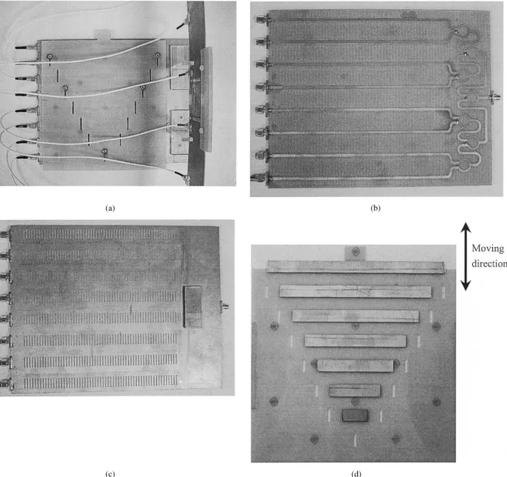
Fig. 1. Structural configuration of eight-element patch antennas array including low-cost phase shifters. (a) Averall antenna system. (b) Top side of feeding network containing Wilkinson power divider and slotted microstrip lines. (c) Bottom side of feeding network including slots array on the ground plane. (d) Phase shifter containing a perturbed card made up of metal strip lines printed on a bare FR4 substrate.
rapidly figure out phase delay angle. Although the accuracy re-mains to be improved; it provides us a fast and easy way to ob-tain a criterion for prototype design. The details will become clear later.
II. A MULTIFUNCTIONALDEVICE: FEEDINGNETWORK AND
PHASESHIFTERDESIGN
After introducing the physical mechanism of our original idea, we have implemented the feeding network, including the metal strips, by the FR4 substrate with double cladding; the relative dielectric constant of the core material is 4.3 at 2 GHz and 1.54 mm in thickness. The width and length of the microstrip line is 3 mm and 185 mm, respectively. The slot is 12 mm in width and 1 mm in length; the period of the slot array is 3 mm. In addition, in order to have uniform amplitudes at the antenna elements, the power dividers have to be connected
to the fed lines. We have implemented seven Wilkinson-based two-way power dividers to enhance the isolation between the two output ports. Also, to reduce the coupling between adjacent lines, the distance between two adjacent lines is set to be 25 mm, which is about eight times the width of microstrip line. The metal strips used to perturb the slots are also printed on a bare FR4 substrate. To have a progressive phase difference between the elements, the difference in the lengths between ad-jacent metal strips must be equal, and then a basic progressive phase difference angle is determined. After dynamically moving the perturbed card, it follows the same fashion for each metal strip directly above the slot array. We can alter the progressive phase difference angle for the feeding network accordingly. It is noted that in order not to introduce the passive intermodulation (PIM) problem [20], the metal strips are coated with a plastic thin film (0.1 mm) to avoid direct contact with the slotted ground plane.
HWANG et al.: BEAM TILTING BASE STATION ANTENNAS 117
(e)
(f)
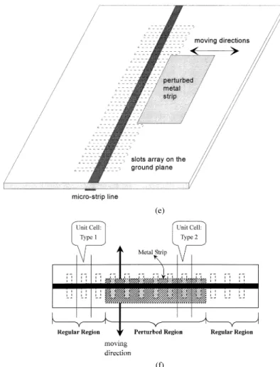
Fig. 1. (Continued) Structural configuration of eight-element patch antennas array including low-cost phase shifters. (e) Structural configuration of a slotted microstrip line perturbed by a metal strip: side view and top view.
Note that although the slots are arranged in a periodic fashion, the frequency of operation is far away from the stopband of such a periodic structure. Thus, the behavior of Bragg reflection is not present in this case. Nevertheless, Bragg reflection inherent in the periodic slot array can be employed as a function of band stop filter to reject the noise that is out of the operating frequency band.
As described previously, we used the finite-element method to calculate the field distribution in the slotted microstrip line perturbed by metal strips, especially for the phase angles at each feed line at various perturbation conditions. Since the overall structure of the feeding network is fairly large in its electrical length, it is difficult to carry out a total simulation. To reduce the simulation cost, we decrease the mutual coupling between two adjacent feed lines by increasing the separation distance and also by using the Wilkinson power divider to isolate them. Thus, the slotted microstrip line partially perturbed by the metal strip can be simulated independently. In addition to the rigorous method, we also used the unit-cell approach to again reduce the simulation time. We first characterize the scattering parameters of the unit cell (or one period) of the slotted microstrip line. If the effect of higher order modes could be neglected at the input and output interfaces, the scattering parameters should be extracted based on the dominant mode. After cascading the unit cells, the input–output relation of the single feed line can be readily obtained. Although this approach neglects the mutual
coupling between two adjacent unit cells and the higher order modes effect, it provides a simple and fast approach to verify our intuition in the prototype design.
In the unit-cell approach, the entire structure is partitioned into three parts, as shown in Fig. 1(e), part 1 and part 3 are the slotted microstrip lines while part 2 is the slotted microstrip line perturbed by the metal strip. The unit cell contains one period of the array. The unit cell in part 1 and part 3 is a microstrip line backed with one slot, while that in part 2 is the former unit cell partially shielded by a metal strip. The scattering parameters of the two types of unit cell are analyzed first. After they are obtained, we cascade them together, in accordance with their corresponding number for constructing the whole structure, to determine the transmission characteristics. In addition, ideally, the unit cell of each type is regarded as the identical one and is independent of its position. In fact, each unit cell has different loading effect at its two ends. As a consequence, it may lead to more or less difference in their scattering parameters.
III. ANARRAYANTENNAWITHPROGRESSIVEPHASEDELAY
According to the array antennas theory, antenna elements with a certain value of progressive phase difference between the elements can steer its radiation main beam toward a certain direction. If we sequentially change the phase difference, we
118 IEEE TRANSACTIONS ON ANTENNAS AND PROPAGATION, VOL. 52, NO. 1, JANUARY 2004
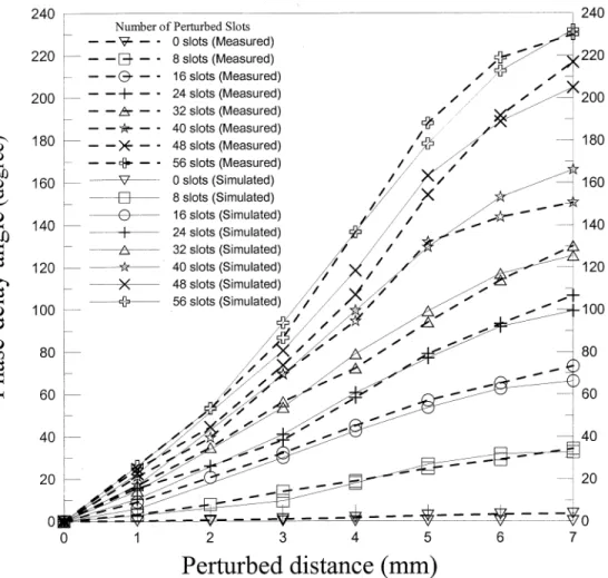
Fig. 2. Variation of phase-delay angle versus perturbation distance for each port (comparison between theoretical and measured results).
continuously steer the main beam within a certain range of spa-tial direction. We consider here an -element antennas array having equal amplitudes and a progressive phase difference. The relationship between the progressive phase difference
angle and the main beam angle is ,
and is the operating wavelength. Moreover, we can build a lookup table for the beam-steering angle and the progressive phase difference angle by this formula. For example, if a main beam is tilting from 0 to 10 , with a 1 step, the progressive phase-delay angles are given as 0.00 , 3.14 , 6.28 , 9.42 , 12.56 , 15.69 , 18.82 , 21.94 , 25.05 , 28.16 , and 31.26 , respectively.
IV. EXPERIMENTAL ANDNUMERICALRESULTS
After having verified the phase shifting characteristics of such a phase shifter, we start to integrate the phase shifter with an eight-element microstrip feed patch antennas array. These patch antennas are arranged linearly with element spacing of 75 mm (half wavelength of the operating frequency 2 GHz). The an-tenna radiation far-field pattern was measured, at a quiet zone distance, in the open site with ground reflection. To obtain a precise measurement, the vector network analyzer (HP8722D) and the low-noise amplifier are used to carry out the close-loop transmission coefficient measurement.
TABLE I
MEASUREDDATA FOR THEMAGNITUDE OFS ATEACHPORT
WITHDIFFERENTPERTURBATIONDISTANCES
To examine the performance of the feeding network to a scanning array, we have measured the phase angle at each port in various perturbed conditions, which essentially are different number of shielding slots and areas. Fig. 2 shows the variation of measured and calculated phase angles versus various per-turbation conditions for each port. The horizontal axis is the perturbation distance and the vertical axis is the phase angle expressed in degrees. Each line drawn with different symbol corresponds to the phase angle at each port. The perturbed dis-tance measured from the edge of the slot is proportional to the shielding area. The numbers of perturbed slots from the second to the eighth feed lines are 8, 16, 24, 32, 40, 48, and 56, respec-tively, whereas the first one is unperturbed slotted microstrip
HWANG et al.: BEAM TILTING BASE STATION ANTENNAS 119
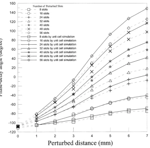
Fig. 3. Variation of phase-delay angle versus perturbation distance of each port (theoretical computation by unit cell approach).
line. The phase angles of each port with the perturbed distance from 0 to 7 mm are displayed in Fig. 2. The phase difference is read from the difference of the adjacent curves for a given per-turbed distance. According to the results from both numerical simulation and measurement, the progressive phase difference angle at each port will increase linearly in accordance with the increase in perturbed distance. Though not shown here, as the perturbation distance increases beyond 7 mm, these curves start to saturate, which is characterized by a gradually diminished phase increment for the increase of perturbed distance. Hence, the progressive phase difference between ports remains almost the same, even if the perturbed distance increases. Since the nu-merical simulation is carried out based on the following ideal assumptions: uniform dielectric constant in the substrate, negli-gible electromagnetic coupling, no gaps between the metal strip and insulator, the differences in the results between the simula-tion and measurement are mainly due to these assumpsimula-tions. For example, the surface flatness of the metal ground plane will re-sult in the imperfect shield for the slot and then the phase angle may deviate from the ideal case.
In addition to measuring the phase angles of at each port, the magnitude of each port in various perturbation conditions is also shown in Table I. The power at each port, on average, is 12.6 dB and the maximum deviation is 2.13 dB in this table. It shows an even power distribution at each port for a given perturbation distance. Ideally, the power at each port is 9 dB; however, due to the insertion loss contributed by the power splitter, the microstrip line, and leakage from the slots
array, it cannot reach the ideal case as we expect. The detailed link budget of the power loss due to each constituent part will be become clear later.
Fig. 3 depicts the simulation results from the two approaches described previously. The lines drawn by the solid line are re-sults obtained from the unit-cell approach while the others (in dashed line) represent that from full-structure simulation. From the results we observe that the difference between these two ap-proaches is considerable when the number of perturbed slots is greater than 16. Since the unit-cell approach does not take into account the mutual coupling among the other unit cells, espe-cially for the perturbed slotted microstrip lines (more coupling occurs), the simulation error will be significant as the number of perturbed slots increases. This is the reason why the unit-cell method is not accurate for the cases having large number of per-turbed slots.
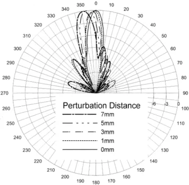
After getting the transmission coefficient at each port, we measured the radiation far-field pattern of the eigh-element patch array antennas integrated with this feeding network. The measurement was taken in the open site with ground reflection; the distance between transmit and receive antennas was 6 m. The radiation pattern for the different perturbed conditions in the feeding network is displayed in Fig. 4. We observe that the radiation main beam is tilting from 360 to 350 as the perturbed distance increases from 0 to 7 mm. In addition, the sidelobe power level is about 15 dB below that of the main beam, which suggests good isolation between the antenna elements.
120 IEEE TRANSACTIONS ON ANTENNAS AND PROPAGATION, VOL. 52, NO. 1, JANUARY 2004
Fig. 4. Radiation pattern of the eight-element patch array antennas.
Fig. 5. Insertion loss of the power divider, microstrip line, and slotted microstrip line.
Due to the presence of slots array, it is indeed a leaky struc-ture. To identify the radiation loss from the leaky structure, we have measured the power loss from each constituent of the an-tenna system. Fig. 5 shows the insertion loss for the microstrip line (185 mm), the slotted microstrip line (185 mm), and the one-to-eight power divider (contains seven Wilkinson-based power dividers). From this figure, we found, at 2 GHz, the insertion loss due to the power divider is about 1.95 dB (on average), and that of the slotted microstrip line is about 1.88 dB. In order to identify the radiation loss from the slots array, we fabricated a microstrip line of the same length but without slots array and measured its insertion loss. It is about
1.2 dB (at 2 GHz). As a consequence, the radiation loss is about 0.68 dB for the slots array. As to the leaky-wave phenomena of the slotted microstrip line, since the leakage from the first higher order mode of the microstrip line occurs at a very high frequency for the present structure parameters, the dominant radiation loss is due to the aperture field of slots induced by the microstrip line. From the measured data of insertion loss demonstrated previously, we may infer that the radiation loss is not considerable.
V. CONCLUSION
In this paper, the microstrip line backed with slotted ground plane is employed as a basic transmission line in the feeding network design. Incorporating with the moveable metal strips partially shielded on these slot arrays, the novel phase shifter is then constructed. By means of dynamical perturbation per-formed on the slot arrays, a reconfigurable feeding network of progressive phase difference between each port can be achieved. The distributions of phase angles at each port in various per-turbed distances are systematically investigated in both theo-retical and experimental studies. In addition, an eight-element patch antenna array system is built underlying such a feeding network. The measured radiation far-field pattern shows excel-lent performance in the beam tilting of this array system.
ACKNOWLEDGMENT
The authors wish to thank Prof. S. T. Peng and F. Y. Chang for their critical reading and useful comments to improve this paper.
REFERENCES
[1] A. Kuramoto, T. Yamane, and N. Endo, “Mechanically steered tracking antenna for land mobile satellite communications,” in Proc. EEE Int.
Symp. Antennas Propagation Society, 1988, pp. 1314–1317.
[2] V. A. Manasson and L. S. Sadovnik, “Monolithic electronically controlled millimeter-wave beam-steering antenna,” in Proc. Silicon
Monolithic Integrated Circuits in RF Systems Topical Meet., 1998, pp.
215–217.
[3] A. D. Brown, L. C. Kempel, and J. L. Volakis, “Design method for an-tenna arrays employing ferrite printed transmission line phase shifters,” in Proc. Inst. Elect. Eng. Microwaves, Antennas Propagat., vol. 149, Feb. 2002, pp. 33–40.
[4] M. F. Iskander, Z. Zhang, Z. Yun, R. Isom, M. Hawkins, R. Emrick, B. Bosco, J. Synowczynski, and B. Gersten, “New phase shifters and phased antenna array designs based on ferroelectric materials and CTS technologies,” in Proc. IEEE MTT-S Int. Microwave Symp. Dig., vol. 1, 2001, pp. 259–262.
[5] P. T. Teo, K. A. Jose, Y. B. Gan, and V. K. Varadan, “Beam scanning of array using ferroelectric phase shifters,” Electron. Lett., vol. 36, pp. 1624–1626, Sept. 2000.
[6] R. R. Romanofsky and A. H. Qureshi, “A model for ferroelectric phase shifters,” IEEE Trans. Magn., vol. 36, pp. 3491–3494, Sept. 2000. [7] M. F. Iskander, Z. Yun, Z. Zhang, R. Jensen, and S. Redd, “Design of
a low-cost 2-D beam-steering antenna using ferroelectric material and CTS technology,” IEEE Trans. Microwave Theory Tech., vol. 49, pp. 1000–1003, May 2001.
[8] N. S. Barker and G. M. Rebeiz, “Optimization of distributed MEMS transmission-line phase shifters-U-band and W-band designs,” IEEE
Trans. Microwave Theory Tech., vol. 48, pp. 1957–1966, Nov. 2000.
[9] C.-W. Back, S. Song, C. Cheon, Y.-K. Kim, and Y. Kwon, “2-D me-chanical beam steering antenna fabricated using MEMS technology,” in
IEEE MTT-S Int. Microwave Symp. Dig., vol. 1, 2001, pp. 211–214.
[10] T.-Y. Yun and K. Chang, “A low-loss time-delay phase shifter controlled by piezoelectric transducer to perturb microstrip line,” IEEE Microwave
HWANG et al.: BEAM TILTING BASE STATION ANTENNAS 121
[11] , “Analysis and optimization of a phase shifter controlled by a piezoelectric transducer,” IEEE Trans. Microwave Theory Tech., vol. 50, pp. 105–111, Jan. 2002.
[12] , “A low-cost 8 to 26.5 GHz phased array antenna using a piezoelec-tric transducer controlled phase shifter,” IEEE Trans. Antennas
Prop-agat., vol. 49, pp. 1290–1298, Sept. 2001.
[13] C. T. Rodenbeck, M.-Y. Li, and K. Chang, “A novel millimeter-wave beam-steering technique using a dielectric-image-line-fed grating film,” in IEEE MTT-S Int. Microwave Symp. Dig., vol. 1, 2001, pp. 267–270. [14] M.-Y. Li and K. Chang, “Novel low-cost beam-steering techniques using
microstrip patch antenna arrays fed by dielectric image lines,” IEEE
Trans. Antennas Propagat., vol. 47, pp. 453–457, Mar. 1999.
[15] , “Novel beam-control techniques using dielectric-image-line-fed microstrip patch-antenna arrays for millimeter-wave applications,”
IEEE Trans. Microwave Theory Tech., vol. 46, pp. 1930–1935, Nov.
1998.
[16] , “New tunable phase shifters using perturbed dielectric image lines,” IEEE Trans. Microwave Theory Tech., vol. 46, pp. 1520–1523, Oct. 1998.
[17] B. Elamaran, I.-M. Chio, L.-Y. Chen, and J.-C. Chiao, “A beam-steerer using reconfigurable PBG ground plane,” in IEEE MTT-S Int.
Mi-crowave Symp. Dig., 2000, pp. 835–838.
[18] C. T. Rodenbeck, M.-Y. Li, and K. Chang, “A novel millimeter-wave beam-steering technique using a dielectric-image-line-fed grating film,” in IEEE MTT-S Int. Microwave Symp. Dig., vol. 1, 2001, pp. 267–270. [19] T. Akiyama, K. Inagaki, and Y. Mizuguchi, “Beam-steering and
multibeam formation of Ku-band phased array antenna using optical signal processing beam-forming network,” in Proc. Int. Topical Meet.
Microwave Photonics, 1999, pp. 173–176.
[20] G. Turner and W. F. Croswell, “RF performance of wire mesh used in deployable spacecraft antennas,” in Proc. IEEE Int. Antennas and
Prop-agation Symp. Dig., vol. 31, June 1993, p. 1646.
Ruey Bing Hwang (M’96) was born in Nantou,
Taiwan, R.O.C, on January 20, 1967. He received the B.S. degree in communication engineering from National Chiao-Tung University, Hsinchu, Taiwan, R.O.C., in 1990, the Master degree in electrical engineering from National Taiwan University, Taipei, Taiwan, R.O.C., in 1992, and the Ph.D. degree in electronics from National Chiao-Tung University, Hsinchu, in 1996.
Following 1996, he joined the National Center of High Performance Computing Hsinchu, as an Asso-ciate Research Scientist. From 1999 to 2000, he was a Postdoctor at the National Chiao-Tung University, Hsinchu. From fall 2000 to spring of 2002, he was a Research Associate Professor in the Microelec-tronics and Information Systems Research Center of National Chio-Tung Uni-versity. Since 2002, he has been an Associate Professor of the Graduate Insti-tute of Communication Engineering, National Chi Nan University, Nantou, Puli, Taiwan, R.O.C. His research interests include guiding and scattering charac-teristics of periodic structures (or photonic crystals), meta-materials, array and array antennas design, and electromagnetic compatibility.
Dr. Hwang is a Member of Phi Tau Phi.
Yin Jung Chang was born in Hualien, Taiwan, R.O.C., on November 26,
1973. He received the B.S. degree in electrical engineering from Tatung Institute of Technology, Taipei, Taiwan, R.O.C. and the M.S. degree from the Graduate School of Communication Engineering, National Chiao-Tung University, Hsinchu, Taiwan, R.O.C., in 1996 and 1998, respectively. He began working toward the Ph.D. degree in electrical engineering at Georgia Institute of Technology, Atlanta, in August 2002.
From 2000 to 2002, he was a Research Engineer in Applied Electromag-netics Research Laboratory, Microelectronics and Information System Research Center, National Chiao-Tung University, Hsinchu, working on array antenna re-search and design for wireless communication applications. His current rere-search interest is in integrated optoelectronics.
Ming-Iu Lai was born in Taiwan, R.O.C., on
November 2, 1976. He received the B.S. degree in electronic engineering from National Taiwan University of Science and Technology, Taipei, Taiwan, R.O.C., in 1998 and the M.S. degree in electrical engineering from National Taiwan University, Taipei, in 2000.
From 2001 to 2002, he was with ZyXEL Com-munication Corporation, Hsinchu, Taiwan, R.O.C., where he worked on digital signal integrity analysis on PCB and electromagnetic interference debuging. In 2002, he joined the Applied Electromagnetic Research Laboratory, Micro-electronics and Information System Research Center, National Chiao-Tung Uni-versity, Hsinchu, Taiwan, R.O.C, where he is working on the design of beam-steering array antenna. His research interests include modeling and design of flip-chip interconnects and packaging in MMIC applications, antenna design, electromagnetic compatibility design on PCB, and numerical electromagnetism.