在WiMAX環境下設計與實作跨越存取服務網路的換手協定
42
0
0
全文
(2) 在 WiMAX 環境下設計與實作跨越存取網路的換手協定 A Design and Implementation of Inter-ASN Mobility over WiMAX Network. 研 究 生:湯佑笙. Student:Yu-Sheng Tang. 指導教授:簡榮宏. Advisor:Rong-Hong Jan. 國 立 交 通 大 學 網 路 工 程 研 究 所 碩 士 論 文. A Thesis Submitted to Institute of Network Engineering College of Computer Science National Chiao Tung University in partial Fulfillment of the Requirements for the Degree of Master in. Computer Science June 2008 Hsinchu, Taiwan, Republic of China. 中華民國九十七年六月.
(3) 在 WiMAX 環境下設計與實作跨越存取服務網路的換手協定. 研究生:湯佑笙. 指導教授:簡榮宏 博士. 國立交通大學網路工程研究所. 摘. 要. 近幾年來,WiMAX 已經成為下一代無線網路的最佳選擇之一。由於無線網路環境日趨成 熟,使得手持式無線裝置日漸增加,而使用者的手持裝置在移動時所產生的換手(Handoff) 問題也日漸重要。WiMAX 點對點網路架構為 WiMAX 網路論壇所提出的無線網路架構,在此 架構中存取服務網路換手(ASN anchored mobility)與連結服務網路換手(CSN anchored mobility) 是 WiMAX 網路的兩種基本網路換手方法。在本篇論文中,我們針對 WiMAX 無線網路架構, 實作存取服務網路換手的 R4 換手方法(R4 mobility)與先期建立資料通道方法(Pre-constructing data path) 。透過實驗的測量結果顯示透過網路架構(WiMAX End-to-End Network Architecture) 的改善能讓換手更具效率亦可以減少換手實的封包遺失及加速換手時間。. i.
(4) A Design and Implementation of Inter-ASN Mobility over WiMAX Networks Student:Yu-Sheng Tang. Advisor:Dr. Rong-Hong Jan. INSTITUTE OF Network AND ENGINERRING NATIONAL CHIAO TUNG UNIVERSITY. Abstract In the recently year, the WiMAX becomes one of the most popular solutions for next generation wireless network. With the growth of mobile devices, the handoff issue is a hot topic in the mobility research. The WiMAX End-to-End Network Architecture proposed by WiMAX Forum is a newly architecture of wireless network, and the ASN and CSN anchored mobility are the basic mobility management for WiMAX networks. In this thesis, we implement the R4 mobility and a pre-constructing data path method in WiMAX environment. The handoff packet loss and handoff delay are evaluated in the proposed methods. The numerical results show that the network assisted mobility management can improve the handoff performance and reduce the packet loss.. ii.
(5) 致謝 在這兩年的研究所生活,首先感謝我的指導教授簡榮宏博士,老師悉心的教導 及在我的研究領域上提供的完善資源,並不時的討論並指點我正確的方向,使我在 這些年中獲益匪淺;論文的完成另外亦得感謝老師的大力協助,使的論文能夠更完 整而嚴謹。 兩年裡的日子中,實驗室裡的學長姐(世昌、安凱、嘉泰、蕙如、家瑋、文彬)、 同學(敬之、宇翔、俊傑、允琳)以及學弟妹們(子興、智賢、淑盈)的共同努力以及 共同生活的點點滴滴,不管是在學術上的討論或者各種活動的共同參與,都讓我的 這兩年的研究生生活變得絢麗多彩,尤其是實驗室的共同出遊更讓我留下許多美好 的回憶。 感謝嘉泰學長忙於自己博士研究外還能提供我研究思考的方向與建議,且總能 在我迷惘時為我解惑,學長對於網路領域的深入瞭解也讓我學習到很多,並且也啟 發了很多不同的思考方向。在碩論研究期間,也感謝財團法人資訊工業策進會網路 多媒體研究所的同仁(智祥、鈺翔、博文、靖倫)的建議與幫助,有你們的建議與 硬體提供測試,讓我能夠順利的完成碩士論文。也感謝同學的幫忙,恭喜我們順利 走過這兩年。 最後想好好感謝我摯愛的家人,由於他們在背後默默的支持以及鼓勵我;在我 這求學期間,家人的關心讓我能專心一致地在研究領域上有所專研,此外交通大學 資訊學院所提供的優良先進的硬體設備也讓我在研究領域上能夠接觸的最新的技術 且毫無旁鶩的專心研究。沒有你們的體諒、包容、支援,相信這兩年的生活將是很 不一樣的光景。 . iii .
(6) Contents Chapter 1. Introduction ............................................................................................................ 1 . Chapter 2. Background ............................................................................................................ 5 . 2.1 Network Functional Entity .............................................................................................. 6 2.1.1 Access Service Network (ASN) ............................................................................... 6 2.1.2 Connectivity Service Network (CSN) ...................................................................... 7 2.2 Reference Points .............................................................................................................. 8 2.2.1 Inter Network Function Entity Reference Point ....................................................... 8 Intra-ASN Reference Point ................................................................................................ 9 Chapter 3. Mobility Management in WiMAX Network Reference Model ........................... 11 . 3.1 The WiMAX End-to-End Protocol Stack ...................................................................... 11 3.2 ASN Anchored Mobility ............................................................................................... 14 3.2.1 HO Preparation Phase ............................................................................................. 16 3.2.2 HO Action Phase .................................................................................................... 17 3.3 CSN Anchored Mobility ................................................................................................ 18 3.4 R4 Mobility ................................................................................................................... 19 3.5 The Pre-constructing Data Path ..................................................................................... 22 Chapter 4. Performance Evaluation ....................................................................................... 25 . iv .
(7) 4.1 Evaluation Tool ............................................................................................................. 25 4.2 Evaluation Environment ................................................................................................ 26 4.3 Evaluation Cases ........................................................................................................... 27 4.4 Numerical Results ......................................................................................................... 28 Chapter 5. Conclusion and Future Work ............................................................................... 31 . Bibliography ............................................................................................................................ 33 . v .
(8) List of Figures and Tables. Figure 1 Relationship between IEEE 802.16 series and NWG End-to-End Network Architecture ..................................................................................................... 3 Figure 2 The WiMAX Network Reference Model (NRM)............................................ 6 Figure 3 The intra-ASN Reference Point (R6, R7, R8) ............................................... 10 Figure 4 The End-to-End Network Architecture Protocol Stack ................................. 12 Figure 5 ASN and CSN Anchored Mobility ................................................................ 13 Figure 6 Message Flow of ASN Anchored Mobility .................................................... 16 Figure 7 CSN Anchored Mobility by DHCP and PMIP protocols .............................. 19 Figure 8 The inter-ASN Mobility (R4 Mobility) Data Path ........................................ 21 Figure 9 R4 Mobility Message Flow ........................................................................... 22 Figure 10 The Predictive Data Path Establishment ..................................................... 24 Figure 11 Evaluation Architecture ............................................................................... 26 Figure 12 Experiment with CSN Anchored Mobility (R3 mobility) ........................... 29 Figure 13 Experiment with R4 mobility ...................................................................... 30 Figure 14 Experiment with Pre-establish Data Path .................................................... 30 Table 1 The Setting of Experiment .............................................................................. 27 Table 2 The Packet Loss Comparison While Handoff ................................................. 30 . vi .
(9) Chapter 1 Introduction . With the growth of the wireless networks in recently year, there are various information services that are supported by the Internet such as VoIP (Voice over IP), multimedia, and real time transmissions. However, the Internet services grow day by day, the high bandwidth and wide radio coverage are necessarily for the network subscribers. The end users can connect to the wireless network not only by the computers but also by the mobile devices such as cell phone, personal digital assistant (PDA), and laptops. Because the handheld devices are so popular and convenience, and devices roaming makes network mobility become an important issue for the wireless network to support users to roam around the wireless environment. IEEE 802.16 series, also known as Worldwide Interoperability Microwave Access (WiMAX), is one of the most popular solution for next generation wireless networks. In particularly, WiMAX has cell range of 30 miles and non-line-of-sight (NLOS) technology based on orthogonal frequency division multiplexing (OFDM), it can construct a metropolitan network that the wireless signal could be received everywhere. Because WiMAX uses different broadband technology from the IEEE 1 .
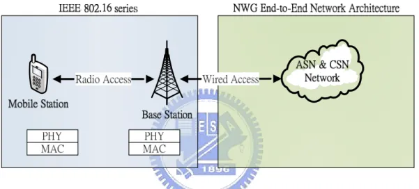
(10) 802.11 (WLAN), there will be 70 Mbps data rate in WiMAX network, which is much better than the IEEE 802.11 wireless network (WLAN) that has several limitations such as narrow transmission coverage and the interference problem. Now, WiMAX is an ongoing project in the WiMAX forum [1], and this group has specified the series of 802.16 standards. The IEEE 802.16-2004 standard [2] standardizes the air interface for fixed broadband wireless access systems. It specified the physical layer (PHY) and Medium Access Control layer (MAC) for fixed WiMAX networks. The IEEE 802.16-2004 is followed by the IEEE 802.16e-2005 standard [3], approved as an amendment to the 802.16-2004, it specified the combined fixed and mobile broadband wireless access systems in PHY and MAC layers. In the end of year 2007, the IEEE 802.16g-2007 [4] was published for the Management Plane Procedures and Services. But, these series of standards only define the PHY and the MAC air link primitives between one MS (Mobile Station) and one BS (Base Station) for functions required in WiMAX network, such as network entry and selection, quality of service (QoS) related parameters, power management modes, and mobility management. However, the network architecture of WiMAX network environment is out of scope of the IEEE 802.16 standards. Therefore, in January 2005, the WiMAX forum specified the WiMAX Forum Network Architecture [5] by the Network Working Group (NWG), and the architecture is called WiMAX End-to-End Network Architecture. The architecture detailed defines the whole WiMAX network scope except the air link between MS and BS. The network architecture specifies various network components with different functions that construct an end-to-end environment. In addition to the network reference model of WiMAX network, it also specifies the functions such as mobility management between BS and other network components, power-saving management between MS and the networks, MS profiles 2 .
(11) that are managed and stored by the network function, packet forwarding path between BS and ASN gateway, IP mobility of the MS, authentication between MS and the network, and the reference point connection between any two network components. Currently, the NWG has released the newest version 1.2 of WiMAX Forum Network Architecture, and it will be improved to version 1.5 at the end of year 2008. Figure 1 shows the relationship between IEEE 802.16 series standards and the NWG WiMAX Network Architecture.. Figure 1 Relationship between IEEE 802.16 series and NWG End-to-End Network Architecture. As mentioned above, the increasing mobility of the wireless network users makes the MS handoff between two BSs frequently. Recently, so many researchers have focused on the topics of wireless network mobility and handoff. Most of them focus on the handoff mechanism between MS and BS, and try to improve the performance and throughput by modifying or re-designing the PHY and MAC layer protocols. Fewer researches have considered the WiMAX Network Architecture for mobility management improvement. But the WiMAX network reference model plays an important role in mobility management of the end-to-end environment. Therefore, the issue how to improve the mobility management of network architecture is also a hot topic in the high mobility network environment. 3 .
(12) In this thesis, we implement the WiMAX Network Reference Model (WiMAX NRM) that can support the network mobility management. The ASN anchored mobility, CSN anchored mobility and R4 mobility are implemented, and we suggest that the R4 mobility can be used to replace the CSN anchored mobility. We also design a pre-constructing data path method for the path registration, and compare it with CSN anchored mobility and R4 mobility. Except for PHY and MAC layer protocol of the IEEE 802.16 standards, we emulate the whole NWG WiMAX Network Architecture which includes the complete network function entities. Based on the proposed emulator, we estimate the packet loss of these mobility methods. We believe that the network architecture is an important factor that can affect the mobility management and handoff performance. The rests of this thesis is organized as follows. Chapter 2 introduces the whole WiMAX Network Reference Model. Chapter 3 characters the different mobility methods, ASN anchored mobility, CSN anchored mobility, R4 mobility and our pre-constructing data path method in the WiMAX end-to-end network environment. Chapter 4, evaluation, shows that the evaluation of packet loss in different mobility methods, and the end of this article are chapter 5, conclusion and feature work.. 4 .
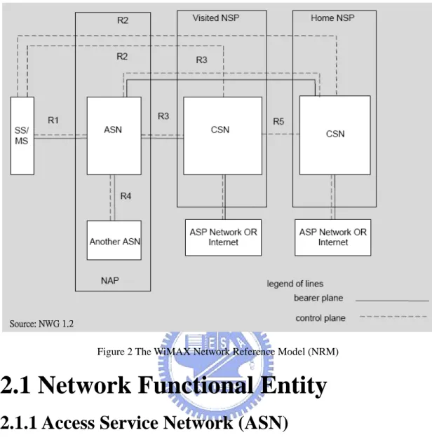
(13) Chapter 2 Background. The WiMAX network architecture can be logically presented by the Network Reference Model (NRM), which divides all the functional entities into different blocks that have different capabilities. As illustrated in Figure 2, the WiMAX NRM divides the whole network architecture into three major network function entities, Mobile Station (MS), Access Service Network (ASN), and Connectivity Service Network (CSN). Also, the graph sketches the reference point connection between any two network components. In Figure 2, the solid line presents that there are Bearer Plane protocols between two network components, and the dotted line presents the Control Plane protocol, they are all in the scope of reference points. We introduce these two parts, network function entity and reference point in following sections.. 5 .
(14) Figure 2 The WiMAX Network Reference Model (NRM). 2.1 Network Functional Entity 2.1.1 Access Service Network (ASN) The ASN defines a logical boundary of the network access service, and it consists of at least one BS and at least one ASN Gateway (ASN-GW), which provides the network access for the MS to access the network. In the ASN network, BS provides the L1 (PHY Layer) and L2 (MAC Layer) functions for the MS to access the radio network and also has a connection to ASN-GW for delivering the L3 (Network Layer) messages. The ASN-GW in the ASN network plays an important role [16], in which it handles all the packets that sends and receives to and from the outer networks. ASN also is a middle proxy server between MS and CSN network that gathers all the information which MS needs. There are network functions between BS and ASN-GW, including data path (DP), context, handover (HO), authentication, service flow (SF), 6 .
(15) paging control (PC), these functions in BS and ASN-GW will exchange control messages for the access service network management. In addition the L3 control message that transmits between BS and ASN-GW, data packet delivering between the BS and ASN-GW is based on the Generic Routing Encapsulation (GRE) tunneling protocol [6], which architecture is called as Data Path (DP). Because ASN-GW and BS are in the two end of data path, the ASN-GW is defined as an anchor point that connects to the outer wired network, and the BS has two interfaces that one is for radio link connecting to MS and the other is for connection to the ASN-GW. In business consideration, the operator that provides the BSs and ASN-GWs to construct an ASN network is called Network Access Provider (NAP), and the access service can be supported by ASN of different NSP.. 2.1.2 Connectivity Service Network (CSN) The CSN provides the IP connectivity services for the MS. Typically the CSN network is an aggregation of the connectivity service servers, it includes the DHCP (Dynamic Host Configuration Protocol) server, AAA (Authentication, Authorization, Accounting) server, policy server, Mobile IP home agent (MIP HA), and other servers that provide MS connectivity services. When the MS initial entries into the serving BS, all associations in PHY and MAC layer between MS and BS will be done first and then follows the MS authentication and IP host configuration, the CSN network will afford all the servers that MS needs for connectivity. Also, when the network provides the Mobile IP (MIP) [7] [8] service for IP connectivity service of MS, the home agent (HA) in the CSN network will be an IP-in-IP packet re-packing agent. HA receives the packets that targets to MS and adds the IP of ASN-GW address (care-of-address, CoA) where the MS is now connecting as destination IP in packet header, then it forwards the packet to the right destination where MS is connecting in. 7 .
(16) MIP is useful for MS be IP mobility and keeping IP connectivity. The same as ASN network, the operator of the CSN network is called Network Service Provider (NSP). When MS is roaming, it can connect to different CSN networks providing by different NSPs. Although we discuss the service servers of CSN network here, the detail of CSN network aggregation is out of scope of the WiMAX End-to-End Network Architecture. The relationship between ASN and CSN network could be multiple ASNs connect to multiple CSN. One ASN network can connect to more than one CSN networks. When MS entries the network, it depends on the user profile to choose the properly CSN for IP connectivity. One CSN network also can connect to multiple ASN networks that could provide various MSs the connectivity service.. 2.2 Reference Points The reference point definition here is the connection between any two network components. It is also the result why WiMAX Network Architecture called the WiMAX End-to-End Network Architecture. In this NRM, two kind of reference point are defined. One is the connection that the two ends are between two network entities, e.g., reference point R1 is between MS and ASN network, the other is the connection that the two ends are between two intra-ASN network entities such as reference point R6 is between BS and ASN-GW. Following we will introduce the eight reference points, R1 to R8, defined in the NRM.. 2.2.1 Inter Network Function Entity Reference Point z. Reference Point R1: The R1 is the connection between MS and the ASN, and it is the radio link between MS and BS. This connection consists of protocols that specified by the PHY and the MAC layer. R1 is under the specification of IEEE 802.16-2004 [2], 802.16e-2005 [3] and 802.16g [4]. 8 . .
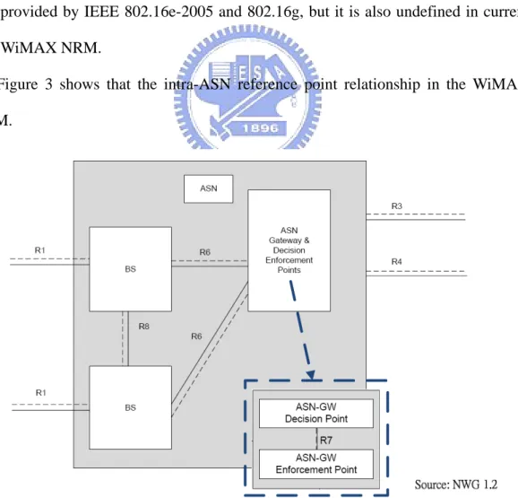
(17) z. Reference Point R2: The R2 is a logical connection between MS and CSN, but R2 does not reflect a direct protocol. This connection handles the protocols such as MS authentication (PKMv2 [9], RADIUS [10]) and IP host configuration (MIP) management, and it is a novel link for connectivity services.. z. Reference Point R3: The R3 is a connection between ASN and CSN network, the Control Plane (e.g., authentication, IP mobility) and the Bearer Plane (e.g. IP-in-IP tunneling) protocol is used. This connection can transfer user data packet between CSN and ASN.. z. Reference Point R4: The R4 reference point is set between two ASNs (or ASN-GWs), and it has Control Plane protocols between ASN-GWs. This connection uses the ASN-GW function to communicate between two ASNs and when MS is roaming inter different ASN domains, the inter-ASN mobility will implement by R4 connection. Because of there is inter-ASN connection, the Bearer Plane protocol in R4 the same as R6 is the GRE tunnel.. z. Reference Point R5: The R5 is the connection between two CSN networks, and it is used when a MS roams to a Visited-CSN, and the Visited-CSN could connect to the MS’s Home-CSN for information retrieval such as Authentication Key (AK) and MS profile. Figure 2 above shows the relationship of the inter network entity reference points. in WiMAX NRM.. Intra-ASN Reference Point z. Reference Point R6: The R6 is a Control Plane and Bearer Plane connection between BS and ASN-GW, and it can handle the data path establishment, modification and cancelation, and send packet through the GRE tunnel. The connection also delivers the mobility control message between BS and ASN-GW 9 . .
(18) for MS mobility. Because the ASN-GW in ASN network is like a management center, the ASN and BS function entity control message will exchange all through the R6 reference point. Here, the data path between BS and ASN-GW is implemented by GRE tunnel and it is the R6 Bearer Plane connection protocol. z. Reference Point R7: The R7 is a connection between the Decision Point and Enforcement Point in the ASN-GW. The decomposition of the ASN-GW function by the R7 is optional depends on the vendors.. z. Reference Point R8: The R8 is a connection between two BSs, and it consists of Control Plane and Bearer Plane protocol for the seamless and fast mobility between BSs. This connection is prepared for the handoff mechanisms that are provided by IEEE 802.16e-2005 and 802.16g, but it is also undefined in current WiMAX NRM. Figure 3 shows that the intra-ASN reference point relationship in the WiMAX. NRM.. Figure 3 The intra-ASN Reference Point (R6, R7, R8). 10 .
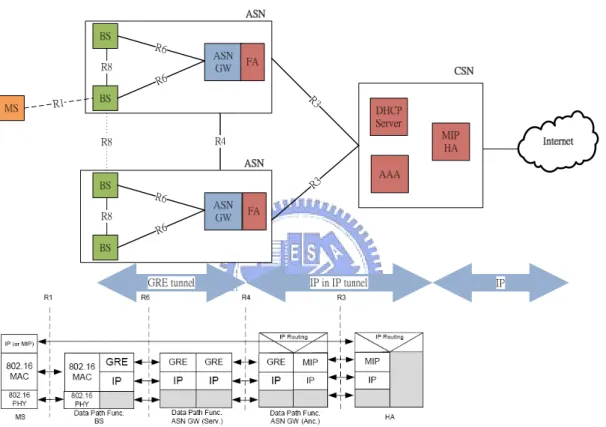
(19) Chapter 3 Mobility Management in WiMAX Network Reference Model. 3.1 The WiMAX End-to-End Protocol Stack Because the WiMAX End-to-End Network Architecture differs from the past wireless network architecture, it also has different protocol stack in data packet delivery. In WiMAX networks, MS will do the following steps to initial network entries: (a) The PHY and MAC layer associate between MS and BS through the radio link, and it is the scope of the R1 reference point connection. (b) User and mobile device authenticate to the AAA server in CSN, and this step will relay the Authentication Key (AK) and other security information to the AAA proxy in the ASN network. (c) MS establishes an intra-ASN data path between serving BS and anchored 11 .
(20) ASN-GW, this is in the scope of R6 and GRE tunnel will be used for data path establishment. (d) The last step is the IP host configuration of MS to CSN, and it makes the MS’s HA available to deliver packet to MS. Figure 4 shows the whole End-to-End Network Architecture and the relationships among MS, BS, ASN-GW, and home agent in protocol stack.. R6. R6. R3. R6. R3. R6. Figure 4 The End-to-End Network Architecture Protocol Stack. We can find that if a corresponding node (CN) wants to send a data packet to MS, the path between MS and CN divides into four different segments: (1) The packet would be sent to HA of MS according to the IP routing protocol. (2) When packet arrives at HA, it checks the binding update (BU) cache in HA to find out which care-of-address (CoA) (or Foreign Agent address, ASN-GW address) MS is now located, then re-packs the packet with CoA in header and sends it. This step is an IP-in-IP tunneling. (3) The ASN-GW/FA receives the packet from HA, and it unpacks the packet to 12 .
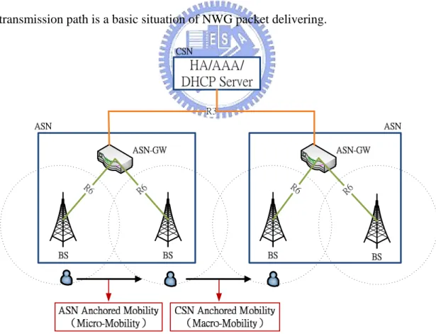
(21) get the MS IP address, according to the MS IP address it will map to the data path id in the DP list of ASN-GW. Because every MS that attach in a BS has a unique DP id between BS and ASN-GW, ASN-GW can use the DP id repacking the packet and sending to the BS where MS attaches to. This connection between BS and ASN-GW is a per-MS connection implemented by GRE protocol. (4) When data packet arrives at BS, it uses the air interface specified by the IEEE 802.16 PHY and MAC layer protocol to send packet through radio link to the MS MAC address. The packet forwarding by four packet-sending steps as shown in Figure 4 is through the path from HA, ASN-GW, BS, and finally arrives at MS. The data packet transmission path is a basic situation of NWG packet delivering.. Figure 5 ASN and CSN Anchored Mobility. The movement of MS from one BS to another BS, the NWG End-to-End Network Architecture is more complicit than the 802.11 wireless networks. When MS 13 .
(22) roams from one BS to another, we must consider that if MS moves to the BS that in the same coverage of anchored ASN-GW or not. According to precedent secxtion, a data path between serving BS and anchored ASN-GW must be established for the connection of MS and CN and HA must do IP host configuration for MS. If MS moves to the target BS that is on the same coverage of ASN-GW (it means the target BS where MS moves to connecting to the same anchor ASN-GW), we call it is an ASN anchored mobility (or R6 mobility). In opposite, if MS move to the target BS that is not in the same coverage of anchor ASN-GW (it means the target BS where MS moves to not connecting to the same anchor ASN-GW), it is the CSN anchored mobility (or R3 mobility). The movement in different ASN network domains is also called the inter-ASN mobility. Figure 5 shows the difference of ASN and CSN anchored mobility and we will introduce the ASN and CSN anchored mobility in detail.. 3.2 ASN Anchored Mobility If MS moves from one BS to another BS and the two BSs is in the same ASN network domain and connect to the same ASN-GW, it is called ASN anchored mobility. The ASN anchored mobility is the same as its name, the anchored ASN will not change when MS roaming, it will only re-establishes the data path between the target BS and anchored ASN-GW. IP address of the MS is also the same because the anchor ASN-GW does not change, HA could find the MS in the same CoA (ASN-GW or FA IP address). Because ASN anchored mobility only replaces the R6 data path, so it is also called R6 mobility. Figure 6 shows the message flow of ASN anchored mobility. We skip the detailed PHY and MAC layer protocols because they are out of our scope. In Figure 6, the serving BS is that MS connects with currently, and the target BS is that MS wants to 14 .
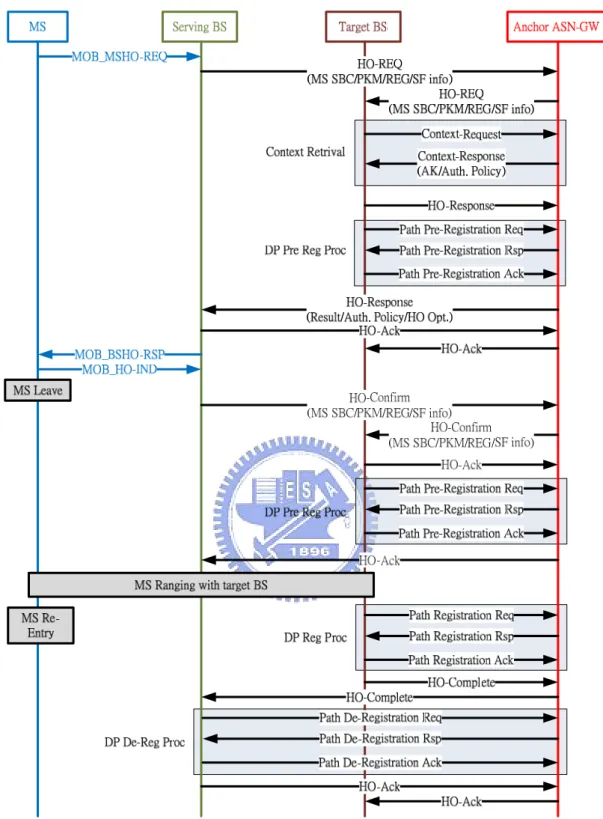
(23) move to. The handoff between the BS and ASN-GW is related to three major functions, those are Hanover Function (HO), Context Function, and Data Path Function (DP), and the control messages in the handoff are all about these functions. We can divide the message flow into two phases, the first phase is the HO Preparation Phase that between MS sends the MOB_MSHO-REQ and MS receives the MOB_MSHO-RSP, and the second phase is the HO Action Phase that between MS sends the MOB_HO-IND and MS completes the handoff.. 15 .
(24) Figure 6 Message Flow of ASN Anchored Mobility . 3.2.1 HO Preparation Phase In this phase, when MS sends the MOB_MSHO-REQ, the serving BS triggers a three-way handshake message of HO Function (HO-REQ/HO-RSP/HO-ACK) to the target BS through anchor ASN-GW. In Figure 6, we can see that in this three-way 16 .
(25) handshake procedure the serving BS sends some MS information such SBC/PKM/Registration/Service Flow to the target BS by HO-REQ. When the target BS receives the HO-REQ from serving BS, it will retrieve the Context Function for the profile of MS stored in ASN-GW by Context-REQ/Context-RSP messages. Then the target BS sends the HO-RSP that including the Result/Authentication Policy/HO Optimization to the serving BS, this information tells the serving BS about the profiles and information of target BS. In the same time of the target BS sending HO-RSP, target BS will start the data path pre-registration procedures by sending three-way handshake message of DP Function (PATH_PRE_REG-REQ/Path_PRE_ REG-RSP/Path_PRE_REG-ACK). This pre-registration procedure will pre-build the data path between the target BS and the anchor ASN-GW, but if one of BS and ASN-GW is not supporting path pre-registration phase, this procedure will not happen. After serving BS receives the HO-RSP, it sends the HO-ACK to the target BS and MOB_BSHO-RSP to the MS, and this step will finish the HO Preparation Phase. MS in this phase is still connecting to the serving BS, and this phase is a preparation for handoff that has not occur.. 3.2.2 HO Action Phase When MS sending the MOB_HO-IND, it means that the MS is leaving the serving BS and has chosen the target BS to handoff, then the serving BS will send HO-Cnf to the target BS to confirm that MS decide to handoff, this confirm message could also include the SBC/PKM/Registration/Service Flow of MS to the target BS. Target BS will replay HO-ACK for the confirm message, in the same time, it can also trigger the path pre-registration procedure for data path between target BS and anchor ASN-GW, this is the second place can do path pre-registration procedure. After all, MS will start ranging with the target BS. If there is no path pre-registration for the 17 .
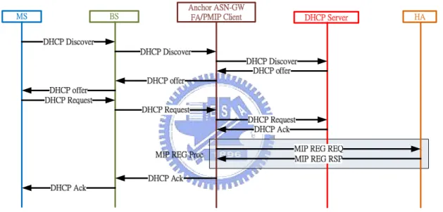
(26) data path, it will start the path registration procedure by PATH _REG-REQ/Path_ REG-RSP/Path_ REG-ACK messages. But, if there was path pre-registration before MS entries, the path registration procedure can reduce to two-way handshake by PATH _REG-REQ/Path_ REG-RSP to enable the pre-registration path. Finally, the HO is almost complete, then target BS will send the HO-Complete to the serving BS. The serving BS cancels the data path between the serving BS and the anchor ASN-GW by PATH_DREG-REQ/Path_DREG-RSP/Path_DREG-ACK messages at first, then replies the HO-ACK to the target BS to finish the ASN anchor mobility procedure.. 3.3 CSN Anchored Mobility Moving from one ASN domain to another is called CSN anchored mobility, and it not only changes the anchor ASN-GW but also changes CoA of MS. In this phase, the procedures of changing the anchor ASN-GW are almost the same as the ASN anchor mobility procedures, and the most different is that the two end of data path will all change (ASN anchor mobility only changes BS but CSN anchored mobility changes the BS and the anchor ASN-GW). After finishing the inner ASN data path establish in CSN anchored mobility, the IP host Configuration of MS will be done by Proxy Mobile IP (PMIP) [11] or Client Mobile IP (CMIP, the same as the MIP [6]) protocol. The CMIP protocol is that the client (MS) supports Mobil IP registration function, so the client can self configure its IP address without assistance of other network component. The PMIP protocol is that MS does not support the Mobile IP registration function, and there is a PMIP client helping sending the Mobile IP registration to HA. PMIP protocol is used with the DHCP protocol for MS mobility service. Because under CMIP protocol MS must support Mobile IPv6 [7] protocol, we will not take it into consideration in our article. CSN anchored mobility is also called R3 mobility 18 .
(27) because the changing of R3 IP-in-IP tunnel. Figure 7 shows the PMIP solution for CSN anchored mobility. The MS will get a DHCP address first by DHCP Discover/Offer/Request/ACK messages, than trigger the PMIP client to register the FA address (or CoA) to HA by MIP_REG_REQ/ MIP_REG_RSP messages. This IP host configuration procedure is combining the DHCP protocol to the PMIP protocol. After the CSN anchored mobility, MS could be found by its new CoA. In the CSN anchored mobility, the data path and the IP-in-IP tunnel will all change.. Figure 7 CSN Anchored Mobility by DHCP and PMIP protocols . 3.4 R4 Mobility ASN and CSN anchored mobility have different mobility domain in MS moving, they also have different handoff latency. In ASN anchored mobility, it only re-establishes the data path between BS and ASN-GW. But in CSN anchored mobility, it must re-establish the data path and the IP host configuration. The CSN anchored mobility sends registration message to the HA, and the HA is a remote server behind the internet. If every time MS moves from one ASN domain to another, then starts CSN anchored mobility, the procedure will spend at least one RTT (round trip time) to 19 .
(28) do Mobile IP registration. It increases the delay time of handoff and if MS is in a highly mobility situation, the throughput will decrease because of the frequently CSN anchored mobility (R3 mobility). Apparently, if it always re-builds the data path (R6) but not the IP-in-IP tunnel (R3) is a better mechanism for MS roaming. R6 mobility will reduce the at least one RTT of the Mobile IP registration to HA and it is more seamless for MS while handoff. The R4 connection is very important for the MS moving inter ASN network, and it is the extension of ASN anchored mobility. Between the ASN-GWs the R4 follows the GRE tunneling protocol in delivering data packet. The R4 mobility connects two ASN-GWs, it can make the anchor ASN-GW unchanged and set up a serving ASN-GW in the middle of anchor ASN-GW and the target BS. Data packet from outsider arrives at anchor ASN-GW than transfers to serving ASN-GW, finally is received by the target BS. The connection among anchor ASN-GW, serving ASN-GW, and target BS is also the data path, so in R4 mobility, MS moving will only rebuild the data path. Figure 8 shows a simple graph how inter-ASN mobility builds the data path and the red dotted line is the data path that after the R4 mobility.. 20 .
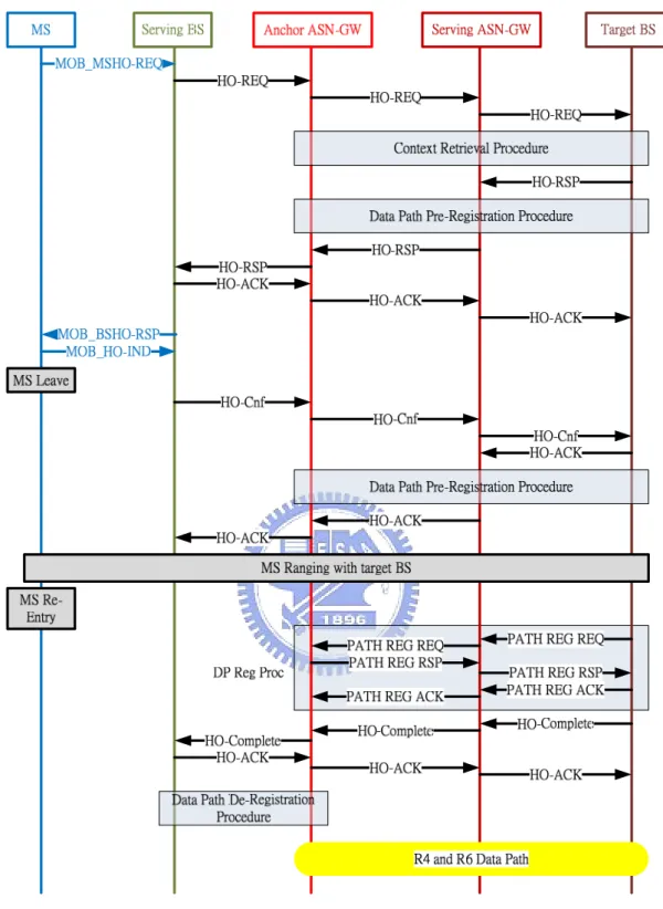
(29) HA/AAA/ DHCP Server R3. R4 R6. R6. R6. R6. Figure 8 The inter-ASN Mobility (R4 Mobility) Data Path. Figure 9 shows the inter-ASN mobility message flow between the network components by R4 mobility. In this graph, we reduce some procedure such as data path pre-registration, context retrieval, data path de-registration, because it is very similar to the ASN anchored mobility message flow in Figure 6.. 21 .
(30) Figure 9 R4 Mobility Message Flow. 3.5 The Pre-constructing Data Path In our research, we implement a pre-constructing method of data path establishment. In this mobility method, we assume that the mobility path of MS is known, so the target BS in the predictive mobility path is a candidate BS for data path 22 .
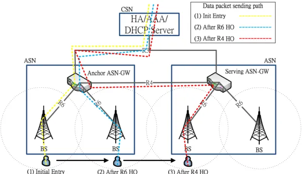
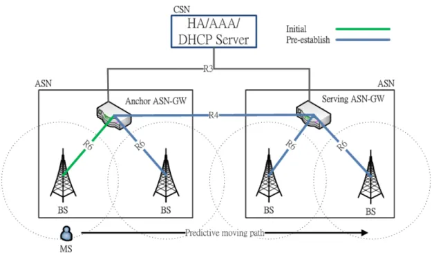
(31) establishment. The pre-constructing data path method knows where the MS going, and then pre-establishes the data path between the BS and the ASN-GW. Even the roaming of MS is inter-ASN mobility, we can pre-constructing the R4 and R6 data path. When MS initial entries the network and establishes the data path among anchor ASN-GW and serving BS, then the anchor ASN-GW will pre-constructing the data path in the predictive data path. The pre-constructing procedure uses the PATH_REG_REQ/PATH_REG_RSP/PATH_REG_ACK. messages. for. data. path. establishment but the pre-constructing data path is not active when MS does not yet roam to the candidate BS. When MS is roaming to the candidate BS (target BS), MS will. send. the. PATH_REG_REQ/PATH_REG_RSP. messages. to. make. the. pre-constructing data path active. In this method, the message flow is similar to the other methods above. The only different is that when MS initial entries, the data path establishes predictive, and when MS roams, the only thing to do about the data path is registering it active. MS does not establish the data path when roam because it is pre-constructing. Figure 10 shows the predictive data path establishment of MS. We can see that the green line of R6 is current data path when MS connect to serving BS, and the blue line of R4 and R6 is that the anchor ASN-GW according to the predictive path of MS to pre-establish the data path. Next chapter we will implement the inter-ASN mobility by R4 mobility and CSN anchored mobility. Also, we implement the predictive data path establishment by using the R4 data path pre-constructing. In the Final, we evaluate and compare these methods in data packet loss.. 23 .
(32) Figure 10 The Predictive Data Path Establishment. 24 .
(33) Chapter 4 Performance Evaluation. In this chapter, we implement the mobility methods in chapter 3 on the WiMAX ASN-GW and BS emulator and evaluate the packet loss of handoff.. 4.1 Evaluation Tool The Institute for Information Industry (III) [12] is in a leadership of WiMAX in Taiwan and the M-Taiwan project that III involved is a goal to make Taiwan be a completely mobility environment. The III is now researching and designing the WiMAX BS and the BS developed by III has already passed the testing by connecting and interflowing with the WiChorus [13] WiMAX ASN-GW. We implement the mobility methods in NWG End-to-End Network Architecture by the ASN-GW and BS emulator supported by III, and the MS is also an emulator that developed in the BS. Although the ASN-GW and BS are just emulators, if we port them into hardware with WiMAX physical specification, the BS and ASN-GW can be real work devices of WiMAX.. 25 .
(34) 4.2 Evaluation Environment. Figure 11 Evaluation Architecture. Figure 11 is the evaluation architecture of WiMAX End-to-End Network Architecture in our article. There are two subnets, ASN-GW_1 connects to the BS_1 and BS_2 is an independent ASN network and also as ASN-GW_2 with BS_3 and BS_4. The whole network is under the local area network (LAN) that has private IP address. The corresponding node (CN) is a packet generator sending packet to MS and the home agent (HA/MIP HA) will receive the packet and repack it in IP-in-IP header then send to the foreign agent (FA/ASN-GW). Following Table 1 shows the experiment parameters.. 26 .
(35) Data Packet size. 64 bytes/packet. Protocol. UDP. Packet Sending interval. Every 60 millisecond/0.06 second. BS to BS interval. 1 second. Experiment duration. 100 seconds. Handoff scenario. Hard handoff. Table 1 The Setting of Experiment. According to the architecture of Figure 11, the MS will move from BS_1 to BS_4 in 100 seconds. At the movement, handoff occurs three times in BS_1 to BS_2, BS_2 to BS_3, and BS_3 to BS_4. When MS leaves the serving BS, it will arrive at the target BS in next second, so the interval between BS to BS is 1 second. Between the MS roaming interval the CN will constantly sending packet to the MS, and we will count the packet loss of MS.. 4.3 Evaluation Cases In this experiment, there are three kinds of handoff will occur. First is the ASN anchored mobility (R6 mobility) between BS_1 and BS_2, BS_3 and BS_4. Between BS_2 and BS_3, the inter-ASN mobility, we will use the CSN anchored mobility (R3 mobility) in case 1 to compare with the R4 mobility in case 2. The CSN anchored mobility will register the new ASN-GW/FA of MS to the HA and the packet will redirect to the new ASN-GW/FA, and the R4 mobility will not change the anchor ASN-GW but build an data path (GRE tunnel) between anchor ASN and serving ASN that the packet from CN will still send to the anchor ASN-GW then follow the data path to the serving ASN-GW and the serving BS. In the case 3, we use the pre-constructing data path in this experiment. We assume that the anchor ASN-GW is already know the moving path of MS and pre-establishes the data path for BS_2, 27 .
(36) BS_3, and BS_4, the BS_3 data path establishment uses the R4 mobility data path concept. The pre-established data path will be active when MS roam to the target BS.. 4.4 Numerical Results Figure 12 and Figure 13 shows the evaluation result of the two handoff mechanisms, CSN anchored mobility (case 1) and R4 mobility (case 2). We can see the packet sequence number accumulates in Figure 12 and Figure 13, there are three broken points in the graph, the first and the third broken points are resulting in the ASN anchored mobility between BS_1 and BS_2, BS_3 and BS_4. The second broken point is the handoff between BS_2 and BS_4, and we can clearly see that in Figure 12 the broken interval is longer than that in Figure 13. The Result shows that if we could use the R4 mobility to replace the R3 mobility in roaming between different ASN domains, the packet loss will decrease. The pre-constructing data path method (case 3) evaluation result is showed in Figure 14, there are also three broken point in the data packet accumulation graph. We could saw that pre-constructing data path case has fewer packet losses than the other two cases. Table 2 shows the total packet loss of handoff in the three cases, we could find that the R4 mobility handoff could decrease the 20% packet loss than the R3 mobility handoff. But the pre-constructing case does not show the significant improvement than the R4 mobility method, although it still has less 10% packet loss. We can figure out the result is that the emulator is not in a real WiMAX hardware and the procedure delay occurs because the experiment setting is six emulator in one kernel, and the pre-constructing data path is still need the PATH_REQ/PATH_RSP message to make the data path active. Although the active message is shorter and fewer, the procedure also speed time in handoff and it causes the packet loss. Table 2 also shows the data packet delay in case 1 and case 2, it apparently presents that the R4 mobility will 28 .
(37) spend more time sending a packet than R3 mobility because R4 mobility will not route the path to the serving ASN-GW. Even the data packet delay is a tinny difference, but the experiment is on the emulator. If we experiment in the real WiMAX environment, the data packet delay will increase and R4 mobility also has its trade-off in MS roaming. We will test this experiment in real WiMAX hardware in future, and we believe that the pre- constructing data path method will show better significant result than other methods.. Figure 12 Case 1: CSN Anchored Mobility (R3 mobility). 29 .
(38) Figure 13 Case 2: R4 mobility. Figure 14 Case 3: Pre-establish Data Path. Case 1: R3 mobility. Case 2:. Case 3:. R4 mobility Predictive. R6 Mobility between BS_1 and BS_2. 59. 42. 35. Inter-ASN mobility between BS_2 and BS_3. 74. 45. 40. R6 Mobility between BS_3 and BS_4. 42. 50. 38. 175/1640. 137/1640. 113. Packet loss rate. 10.67%. 8.35%. 6.89%. The inter-ASN handoff delay. 4.44 sec. 2.7 sec. 2.4 sec. 64ms. 93ms. Total packet loss (loss/total). The data packet delay after inter-ASN HO. Table 2 The Packet Loss Comparison While Handoff. 30 .
(39) Chapter 5 Conclusion and Future Work. In our thesis, we implement the R4 mobility between two ASN-GWs to replace the CSN anchored mobility of inter-ASN mobility and use the R4 mobility to implement a pre-establishment data path method. In the highly mobility environment, the seamless handoff is an very popular topic in WiMAX network, and the improvement of handoff could not only in the IEEE 802.16 PHY and MAC layer protocol but also could be in the End-to-End Network Architecture. Because the network architecture is the special feature of WiMAX, the network environment assistant handoff would be a workable method to improve the handoff in WiMAX network. We have emulated the WiMAX End-to-End Network Architecture and evaluated the packet loss of R3, R4, and R6 mobility in this article, but it only uses hard HO method between MS and BS. In the future, we will do the experiment in the real WiMAX hardware and try other mobility methods according to the network architecture or the MS/BS handoff scenarios to improve the network assistant handoff by the design of ASN-GW and BS. And also we will implement the data integrity method in ASN-GW for buffering the 31 .
(40) data packet to reduce the data packet loss when MS roaming. Because ASN-GW is an central role in ASN network, the information gathering in ASN-GW can be numerous MSs, so how to make the resource in better using is also a research topic in our future work.. 32 .
(41) Bibliography. [1] WiMAX Forum. [Online] http://www.wimaxforum.org [2] IEEE Std 802.16-2004. TM. , IEEE Standard for Local and Metropolitan Area. Networks - Part 16: Air Interface for Fixed Broadband Wireless Access Systems, Oct 2004. [3] IEEE Std 802.16e-2005TM, IEEE Standard for Local and Metropolitan Area Networks - Part 16: Air Interface for Fixed and Mobile Broadband Wireless Access Systems, Feb 2006. [4] IEEE Std 802.16g-2007 TM, IEEE Standard for Local and Metropolitan Area Networks - Part 16: Air Interface for Fixed and Mobile Broadband Wireless Access Systems - Management Plane Procedures and Services, Dec 2007. [5] WiMAX Forum Proprietary, “WiMAX End-to-End System Architecture (Stage 2: Architecture Tents, Reference Model and Reference Points, Stage3: Detailed Protocols and Procedures),” January 11, 2008 Release 1.2.1. [6] D. Farinacci, T. Li, S. Hanks, D. Meyer, P. Traina, "Generic Routing Encapsulation (GRE)," RFC 2784, Internet Engineering Task Force, March 2000. [7] C. Perkins, Ed., “IP Mobility Support for IPv4,” RFC 3344, Internet Engineering Task Force, August 2002. 33 .
(42) [8] D. Johnson, C. Perkins, J. Arkko, “Mobility Support in IPv6,” RFC 3775, Internet Engineering Task Force, June 2004 [9] D. Johnston,. J. Walker,. "Mutual. Authorization. for. PKMv2,". IEEE. C802.16e-04/229, 2004. [10] C Rigney, A Rubens, W Simpson, S Willens, “Remote Authentication Dial In User Service (RADIUS),” RFC 2865, Internet Engineering Task Force, June 2002. [11] K Leung, G Dommety, P Yegani, K Chowdhury, “WiMAX Forum/3GPP2 Proxy Mobile IPv4,” draft-leung-mip4-proxy-mode-07, Internet Engineering Task Force, Feb, 2008. [12] Institute for Information Industry (III), organization in Taiwan. [Online] http://www.iii.org.tw/ [13] WiChorus. [Online] http://www.wichorus.com/ [14] P. lyer, N. Natatajan, M. Venkatachalam, A. Bedekar, E. Gonen, K. Etemad, P. Taaghol, “All-IP Network Architecture for Mobile WiMAX,” Mobile WiMAX Symposium, 2007. IEEE [15] S. Das, T. Klein, A. Rajkumar, S. Rangarajan, M. Turber, H. Viswanathan, “System Aspects and Handover Management for IEEE 802.16e,” Bell Labs Technical Journal, 2006. [16] M. Ergen, “The Access Service Network in WiMAX: The Role of ASN-GW,” WiChorus, Inc.. 34 .
(43)
數據
+7
相關文件
Private Sub Dir1_change() File1.Path = Dir1.Path updatePath.
Step 3: : : :模擬環境設定 模擬環境設定 模擬環境設定 模擬環境設定、 、 、 、存檔與執行模擬 存檔與執行模擬
Private Sub Dir1_change() File1.Path = Dir1.Path updatePath.
To complete the “plumbing” of associating our vertex data with variables in our shader programs, you need to tell WebGL where in our buffer object to find the vertex data, and
Is end-to-end congestion control sufficient for fair and efficient network usage. If not, what should we do
◉ These limitations of vanilla seq2seq make human-machine conversations boring and shallow.. How can we overcome these limitations and move towards deeper
– evolve the algorithm into an end-to-end system for ball detection and tracking of broadcast tennis video g. – analyze the tactics of players and winning-patterns, and hence
• By Lemma 2, for any vertex v, the longest path start on one side of the midpoint edge and go to the opposite end of the diameter... Group the Swap
