國
立
交
通
大
學
資訊科學與工程研究所
碩
士
論
文
針對 P2P 移時串流系統之影音檔案儲存
Distributed Video Storage Management for a P2P Time‐Shift
Streaming System
研 究 生:廖威凱
指導教授:張明峰 教授
中 華 民 國 九 十 八 年 八 月
針對 P2P 移時串流系統之影音檔案儲存
Distributed Video Storage Management for a P2P Time‐Shift Streaming System研 究 生: 廖威凱
Student:Wei-Kai Liao
指導教授: 張明峰
Advisor:Ming-Feng Chang
國 立 交 通 大 學
資 訊 科 學 與 工 程 研 究 所
碩 士 論 文
A Thesis
Submitted to Institute of Computer Science and Engineering College of Computer Science
National Chiao Tung University in partial Fulfillment of the Requirements
for the Degree of Master in Computer Science July 2009
Hsinchu, Taiwan, Republic of China
針對
P2P 移時串流系統之影音檔案儲存
學生:廖威凱 指導教授:張明峰 教授 國立交通大學資訊科學與工程研究所 摘要 現今的 P2P 影音串流主要分為實況影音串流和隨選視訊串流,透過 P2P 的方 式來提供影音串流的服務。然而收看實況影音串流的使用者只能收看最新的影音 內容,無法收看過去時間的影音內容;收看隨選視訊串流的使用者雖然可以隨自 己喜好隨選隨看,但無法收看即時的實況影音。 雖然過去有很多和 P2P 影音串流的研究,但是目前並還沒有任何研究明確的 實作出能支援移時播放的 P2P 影音串流系統,我們提出一套針對 P2P 移時串流系 統之影音檔案儲存方法,借由這個方法,開發一套支援實況和移時串流的系統, 使用者可以依自己喜好來選擇收看實況的影音串流或是移時串流。 在我們的系統中,每個使用者一個短期的儲存器和一個長期的儲存器,我們 提出一個演算法來,將短期儲存器內部份的影音內容移至長期的儲存器,除此之 外,當要存的影音內容超過我們的儲存器大小時,我們也提出一套合適的替換機 制。Distributed Video Storage Management for
a P2P Time-Shift Streaming System
Student: Wei‐Kai Liao Advisor: Prof. Ming‐Feng Chang
Institute of Computer Science and Engineering
National Chiao Tung University
Abstract
P2P multimedia streaming today can be categorized into live streaming and video‐on‐demand (VoD) streaming; both adopt P2P techniques to provide multimedia streaming services. However, live streaming users can only watch the latest media contents but cannot watch previous ones. Although VoD streaming users can watch what they want at any given time, they cannot watch live media content.
Although there are many studies about P2P live streaming and P2P VoD streaming, there are no P2P streaming systems that can provide both live and time‐shift streaming at the same time. In this thesis, we propose a storage policy for P2P time‐shift streaming contents. Based on the storage policy, we implement a P2P streaming system that can providing time‐shift streaming and live streaming at the same time.
In our streaming system, each peer maintains a short‐term storage and a long‐term storage. We propose an algorithm to turn part of media contents in short‐term storage to long‐term storage. Besides, in order to prevent the size of media content exceed the size of storage; we also propose a replacement policy.
誌謝
首先我要感謝論文的指導老師 張明峰教授。教授仔細耐心的指導,讓我 學會獨立思考與作研究的方法;在構思此論文時,也多次指正我思考的盲點,讓 我可以順利完成這篇論文。我很感謝在求學過程中,能接受張教授的指導,研究 所這兩年獲益匪淺。 我也要感謝實驗室的同仁,玄亞同學、柏瑞同學,和我一起修課一起熬夜 寫程式,一起同甘共苦,讓我兩年過得有聲有色。也感謝岳廷、茂弘、祐村等學 弟,讓我這段時間的生活增添不少色彩。 最後要感謝我的家人,感謝你們在我求學期間全心全意的支持,讓我可以 順利的完成學業。廖 威 凱 謹識於 國立交通大學資訊科學與工程研究所碩士班 中華民國九十八年八月
Contents
摘要... i Abstract ………...………ii 誌謝... iii Contents ... iv List of Figures ... vi Chapter 1 Introduction... 1 1.1 Current development ... 1 1.2 Motivation ... 2 1.3 Objective ... 3 1.4 Summary ... 4
Chapter 2 Related Work ... 5
2.1 Classification of P2P streaming Methods ... 5
2.2 Data Transmission ... 7
2.3 P2P live streaming ... 8
2.4 P2P VoD streaming... 9
2.5 P2P live streaming with Time-shift streaming Features ... 11
Chapter 3 System Design ... 14
3.1 System Overview ... 14
3.2 Streaming Format... 16
3.3 Storage Architecture ... 19
3.3.2 Operation of Short-term storage ... 22
3.3.3 Operation of Long-term storage ... 24
3.4 Live streaming ... 27
3.5 Time-shift streaming ... 28
3.5.1 Gossip Target Selection ... 28
3.5.2 Gossip Search ... 30
Chapter 4 System Implementation and Analysis ... 31
4.1 Index Server ... 31
4.2 System analysis ... 32
Chapter 5 Conclusions and Future Work ... 35
Reference ... 36
List of Figures
Figure 2.1 IPTV architecture for time-shift. ... 12
Figure 3.1 System Architecture. ... 15
Figure 3.2-1 An example of stream depcomposition. ... 17
Figure 3.2-2 Streaming format in our system ... 18
Figure 3.3 Live streaming group and time-shift streaming groups ... 20
Figure 3.3.1 Peers in time-shift group ... 21
Figure 3.3.2-1 Operations of short-term storage ... 22
Figure 3.3.2-2 De-registration of short-term storage ... 23
Figure 3.3.3-1 Turn short-term storage to Long-term storage ... 24
Figure 3.3.3-2 Algorithm of long-term storage ... 26
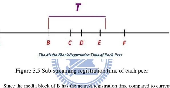
Figure 3.5 Sub-streaming registration time of each peer ... 29
Figure 4.1-1 Registration message ... 31
Figure 4.1-2 Feedback message ... 32
Figure 4.2 (a) Storage range of long-term storage ... 33
Figure 4.2 (b) Storage range of long-term storage ... 33
Chapter 1 Introduction
1.1 Current Development
In client-server network architecture, each computer acts as either a client or server. Client-server architecture illustrates the relationship between two computers in which one is a client, which makes service requests to another computer, a server. The upside of client-server architecture is easy to handle and extend its scale. However, with the increase of the requests by the clients, the server may be soon overloaded, and unable to deliver or poorly deliver the requested data.
In contrast to client-server architecture, peer to peer (P2P) architecture illustrates another relationship between two computers in network architecture. In recent years, P2P networks and P2P applications have been emerging as one of the most promising approaches to address the scalability problem. Unlike client-server networks, where network information is stored on a centralized server and made available to tens, hundreds, or thousands of clients, in P2P network, all peers have equivalent function, they share a part of their own resource such as storage capacity, file content, computing power to other peers. In other words, in P2P network, all peer acts as both a client and a server at the same time and collaborate with each other instead of relying on centralized servers.
It is obvious that P2P network is good in scalability. Beside it provides for peers an easy way to share and exchange information without the need of costly and difficult to maintain the central server. The first P2P application is Naptster [1], that was used for mp3 music file sharing. Napster totally overthrows the traditional client-server network architecture. After that, P2P-related applications for file sharing develop rapidly. ezPeer [2], eDonkey [3], eMule [4], Kazaa [5] and BitTorrent [6] are very popular file sharing software at present.
In addition to file sharing, there are some P2P applications also applied in other domain such as telephony and video streaming. Skype [7], a famous P2P telephony application, routes voice packets from callers to callees over P2P network, and allows
users to make phone calls over the Internet. Skype realizes real-time voice communication over P2P network.
1.2 Motivation
P2P streaming is another emerging domain on P2P applications, such as PPStream [8], PPlive [9], etc. In general, P2P streaming system can be categorized into two basic typologies: (1) In P2P live streaming systems, users choose from different channels and watch the live content together. In other words, users claim synchronous video content, in order to maintain the playback quality. Reducing end-to-end delay is an important issue in P2P live streaming system. (2) In P2P VoD (Video-on-Demand) streaming systems, the users may choose a specific movie and play it at any time because the video has been recorded in advance.
However, these two streaming system do not provide users watch time-shift streaming (or called live-shift streaming). In time-shift streaming systems, users can watch a live streaming with arbitrary offset of time, i.e., users can watch a live program from the beginning even when this live program has already started playing for a while. For example, someone likes to watch a ball game from the beginning but he misses the start time of the game, or someone likes to replay some spectacular moments in a program. These are very practical situations but there is no P2P streaming system that can provide time-shift streaming at present. That is because there are some difficult problems in developing and designing a P2P time-shift streaming system.
Since in both P2P VoD and time-shift streaming, users play a program at any time, the video content they claim are asynchronous, we can treat P2P time-shift streaming as a special case of P2P VoD system. The main difference between these two streaming systems is the length of video. In P2P VoD streaming system, the length of video are always fixed, but in P2P time-shift streaming, the length of video can be very long. Obviously, if a time-shift streaming system wants to provide users watch arbitrary offset of live content, storage policy for time-shift video content is a serious problem.
Although there are many studies about P2P live streaming and P2P VoD streaming, quite few studies can support P2P live and time-shift streaming at the same time. LiveShift [10], P2TSS [11] and IPTV [12] are the only three studies mention about time-shift streaming, but all of the three studies are just prototypes and have not been implemented. On the other hand, studies about P2P VoD are very plentiful. Huang analyzes Microsoft client-server VoD system and outcomes that P2P VoD system can decrease the overhead of the VoD server. Because in P2P VoD streaming system, storing vast video content by using the storage of peers, and enabling peers to share their stored video content instead of always requesting video content from VoD servers. To conclude our above discussion, it is worth to design a P2P time-shift streaming system, using P2P network architecture to decrease the overhead of a dedicated time-shift server and to provide time-shift streaming and live streaming at the same time.
1.3 Objective
In this thesis, we propose a P2P time-shift streaming system which can play live streaming and time-shift streaming. Although P2P time-shift streaming is different from P2P live and P2P VoD streaming functionally, by studying documents of P2P live streaming and P2P VoD streaming, we conclude that our P2P time-shift streaming system should cope well with the following issues:
(1) Storage and search policy of the time-shift streaming content. (2) Management of live and time-shift group.
(3) Transmission architecture for live streaming and time-shift streaming. (4) Prefetch policy for time-shift streaming content.
These four issues are associated with storage policy. Therefore, the storage policy is the most important in our system. We propose an effective storage policy that not only decides how to use storage efficiently and what video content should be stored but also helps peers sharing and delivering their video content efficiently.
Our P2P time-shift streaming system has been designed based on our proposed storage policy. We believe our work is valuable since there are no existing P2P streaming systems that can actually provide time-shift and live streaming at the same time.
1.4 Summary
The remaining part is organized as follows. Chapter 2 describes the current work in P2P streaming researches related to our system. Chapter 3 shows our system design in details. Chapter 4 presents the system implementation and system analyzsis. Finally, we give our conclusions in Chapter 5.
Chapter 2 Related Work
In this chapter, first we describe three overlay topologies used in P2P streaming systems and explain the data transmission. Then we introduce the current work of P2P live and P2P VoD streaming. There are a few researches on P2P streaming that have time-shift function, and we will give a briefly introduction.
There are three important criterions in designing P2P streaming systems.
1. Setup delay, means the time from the user tunes on one channel to the time the video is visible.
2. End-to-end delay, also called playback delay, means the delay between source and the receiver.
3. Playback continuity means the percentage of received packet.
2.1 Classification of P2P Streaming Methods
Despite P2P live streaming systems and P2P VoD streaming systems are quite different. Their basic overlay topology can be classified into three categories: tree-based overlay and mesh-based overlay.
(1) Tree-based overlay
1. Single-tree streaming
The tree-based method constructs a tree-shaped graph. The source node transmits media streaming data to interior nodes and the interior nodes forward the data to their downstream nodes, which means every node receives data from its parent. The
architectures of Narada [13] and NICE [14] are both tree-based. This intuitional method has less SETUP delay, and no need to transmit extra messages to maintain the overlay. But the tree-based method suffered some disadvantages:
1. it’s not load-balancing; most nodes in tree-shaped topology are leaf nodes, but these nodes don’t have to forward data to another node. On the other hand, interior nodes must contribute its bandwidth.
2. it’s not robust and resilient. In this system, every node has a parent. If the parent suddenly fails, the downstream nodes lose data instantly. For a system in a high churn environment, the tree must be destroyed and rebuilt frequently, which will cause much overhead.
2. Multi-tree streaming
To resolve the problems of single-tree systems, it has been proposed to build multiple trees for delivering data. This method can minimize the effect of churn and effectively utilize available resources in the system. The source node of the multiple-tree will split a video stream into more than two substreams and deliver the substreams to the distinct multiple trees. This method distributes the forwarding load among nodes and exploits the bandwidth of the links among the nodes. SplitStream [15] and CoopNet [16] are multiple-tree based architecture.
(2) mesh- based method
Mesh-based overlays implement a mesh distribution graph. Each node in the system connects to partial nodes in the overlay. And each node has a buffer map which represents its available data, and nodes exchange the buffer maps. Each node must identify where the available chunks are, and pulls the chunks it requires. Successful systems like PPLive [9], CoolStreaming [17], and SopCast [18] are
mesh-based methods. Mesh-based systems have long SETUP delay and have the overhead of extra control messages exchange. But this kind of systems offers good resilience to node failures.
2.2 Data Transmission
In the early stage, there are two mechanism of data transmission in P2P streaming system. One is push-based mechanism; another is pull-based mechanism. Both of the two has its own drawback, in order to overcome the drawbacks, a hybrid mechanism was proposed, called push-pull mechanism.
1. Push mechanism
The push mechanism means that when a peer has received data, this peer forwards the received data to other peers in the network, without explicit requests from other peers. The forwarding decision is based on some predetermined routing algorithm, and the same algorithm is globally used over the whole network. The problem in push-based systems is recovering the lost data, since the lack of requests for data. For example, if a connection between two peers is broken, a sending peer will fail to forward the data to the receiving peer across this broken connection.
2. Pull mechanism
In a pull-based system, a peer receives a packet from other peers must request it prior to receiving. After receiving a packet, peer must notify other peers about the packet it received in order to pass the stream along in the network, thus enabling other peers to request the data. However, if for some reason a packet is not received by a peer, it may request it from one or more peers announcing to have that packet. This
results in better resilience in reception, because in case of a failure the receiving peer can redirect request packets to another peer having the desired data. An obvious weakness in the pull-based mechanism is SETUP-delay, since in pull-based mechanism peers always take much more effort to get needed data.
3. push-pull mechanism
The newly trend is push-pull mechanism, retrieving the advantages of push-based and pull-based mechanism. In this hybrid mechanism, peers send request message to parent instead of sending request message for each data. For example, a peer pulls/requests one block and its parent push/forwards ten block to him.
2.3 P2P live Streaming
P2P live streaming overlay can be classified into tree-based overlay and mesh-based overlay. In tree-based overlay, the root of the tree is the source of the live content. The live content spread from the root to other peers. Peers must transmit streaming that it just received.
In ADSL client, since its gap between upload bandwidth and download bandwidth is wide, i.e., 2M bits for download bandwidth and 256K bits for upload bandwidth, the upload bandwidth usually makes serious bottleneck in multicast tree. In order to utilize upload bandwidth efficiently and provide more reliable media transmission, in recent year, most P2P streaming systems adopt multi-tree structure.
The advantage of multi-tree structure is that the transmission delay is usually shorter because the streaming data is transmitted along the fixed paths. However,
when peer churn, which represents the phenomenon that peers join and leave the system very often, occurs frequently, the delay caused by re-construction of the multi-tree topology grows; therefore the system could not support smooth streaming transmission.
In order to overcome the peer churn issue, many systems adopt mesh structure, which is so-called data-driven infrastructure. These systems do not build a specific overlay network or transmission paths in advance. Instead, they use gossip-based protocol to exchange media contents each peer needs. According to how peers require media content, tree-based structure can be classified into push-based structure since the parent nodes voluntarily transmit data to their child nodes, while mesh structure can be classified into pull-based structure since the peers request what they want among all peers and the requested peers transmit data to them thereafter.
2.4 P2P VoD Streaming
Video-on-demand service (VoD) allows users to watch any point of video at any time. Compared with live streaming, VoD offers more flexibility and convenience to users and truly realizes the goal of watch whatever you want whenever you want. VoD has been identified as the key feature to attract consumers to IPTV service.
However, in the early days, in some P2P VoD streaming systems, such as P2Cast and P2VoD, users can only watch the video from the beginning. Both P2Cast and P2Vod adopt single-tree structure. In P2Cast, each peer uses large disk storage to store the beginning part of video and the part of the close-at-hand video segment, and provides these parts for the newly joined peers in the future. In P2Vod, peers that
watch near region of video content form a generation. Peers belong to the same generation must keep the consistency of their playback buffer. This mechanism simplifies the complexity in recovering the multicast tree after peer churn occurs, but the cost is decreasing the utilization of storage, since in the same generation, all peers store the same video content. Besides, in P2Cast and P2Vod, the newly joined peers cannot contribute all of video content that they had due, this constrain is due to the cache policy and session establishment in their systems. Another system, oStream [19], users can watch random part of the video, but the video playing would be broken for a while if peers as the children of the newly joined peer.
Recently, most P2P VoD streaming systems adopt mesh overlay network. BASS [20] uses BitTorrent protocol to download the video content. When close to the playback deadline but the video content has not been arrived yet, the peer will get the video content from the VoD server directly. From its simulation, this mechanism helps reducing 34% of the bandwidth of the VoD server when upload bit rate equals to play rate in VoD client. Although BASS reduces the overhead of VoD server, with the increasing of users, the VoD still requires more bandwidth to serve client.
Besides, in BitTorrent, peers share data based on tit-for-tat principle. This tit-for-tat is not suitable for P2P VoD streaming, in P2P streaming, video content are delay-sensitive, i.e., peers must receive data in time, however, tit-for-tat principle usually make delay increasing. PONDER [21] employs the mesh-based approach similar to BitTorrent but adopts some new mechanisms to accommodate the VoD service.
PONDER divides video into multiple equal-size segments called sub-clips, and each sub-clip divided into multiple equal-size segments called chunk. In PONDER,
each peer select serving peer base on the same principle, the principle makes the peer that request urgent video content have higher priority to be served. By adopting this principle, each peer can receive maximum video content before the deadline of playback buffer. If peers cannot receive video content before the deadline of playback buffer, peers can receive from VoD server directly. PONDER has better efficiency than BASS, when upload bit rate is 112% to play rate, PONDER can decrease 93% bandwidth overhead of VoD server.
Many commercial P2P VoD streaming systems appear to provide streaming services and successfully attract a huge amount of users in recent years, such as PPLive, Joost [22], PPStream, UUSee [23] and GridCast [24]. More and more new P2P VoD streaming systems with better quality or even more fascinating features will arise in the near future.
2.5 P2P Live Streaming with Time-Shift Streaming Features
P2TSS, LiveShift and IPTV are the only three researches we found that providing users watch time-shift streaming. But so far, all of these are just prototypes and have not been implemented into well-organized systems yet. We will give a brief a brief introduction of these researches.P2TSS can provide live and time-shift streams. To achieve this, it uses two distributed cache algorithms, Initial Play-out Position Caching and Live Stream Position Caching. These algorithms enable peers to locally decide which video blocks to cache for sharing with other peers. Its simulation results show that P2TSS achieves low server stress by utilizing the local cache and upload bandwidth of peers.
networks for both transmission of live video and storage of past video data. In order to the video data for time-shift, video packets must include timing information. Peers receiving a live or time-shifted streaming and store the video in a memory buffer. When the buffer reaches a predefined storage size, the segment then may be stored on a long-lasting storage. After storing the segment, the peer adds a reference to the segment in the DHT. Each peer only has to store some video content that they just watched.
IPTV provides four main functions: live streaming, VoD streaming, PVR (Personal Video Recorder) and time-shift streaming. Figure 2.1 shows the system architecture of the IPTV.
Figure 2.1 IPTV architecture for time-shift
It contains three modules: Proxy, Cache and Client. The Proxy node receives media content from source and transmits this content using multicast. It also caches the content and publishes the metadata from where the Cache and Client node can
obtain them. The Cache node receives the multicast content and then subsequently writes it in a file. The Client node plays the content received either by multicast or by P2P methods. For live content, the Client joins the multicast group to receive the stream. For time-shift content, the Client node first obtains the metadata from the Proxy node and retrieves a list of peers, including other Client nodes and Cache nodes, and then starts to download the content through P2P if transmitted from Client nodes or directly if transmitted from Cache nodes.
Chapter 3 System Design
P2P time-shift streaming is similar to P2P VoD streaming. The main difference between these two streaming systems is the length of video. In P2P VoD streaming system, the length of video are always fixed, but in P2P time-shift streaming, the length of video is infinite due to the time is also infinite. Obviously, in P2P time-shift streaming, storage policy is a serious problem.
For this reason, we propose a storage policy to implement out P2P time-shift streaming system. Based on our storage policy, providing users can watch time-shift video smoothly. Our storage policy will cope with the following issue well:
(1) Deciding what kind of streaming packet should be stored. (2) How to efficiently exploit the storage space with limited size. (3) How a peer adds its reference about what it has been stored.
Furthermore, following the storage policy, we also propose other detailed issues including:
(1) How data transmission in live streaming and time-shift streaming. (2) Why need to form time-shift group.
(3) How to form a time-shift group.
We will introduce the overview of our system at first, and then introduce our storage policy and other detailed issues.
3.1 System Overview
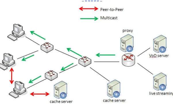
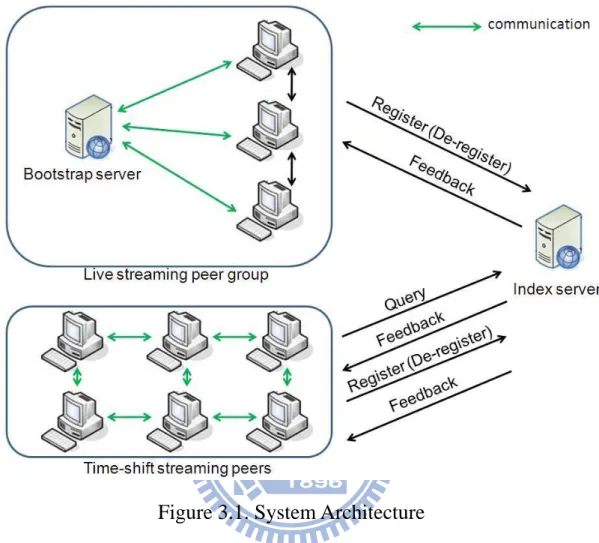
Our system contains four main parts: live streaming peers, time-shift streaming peers, a bootstrap server and an index server. The Figure 3.1 depicts our system
architecture and simply introduces the relation between each two entities in the system.
Figure 3.1. System Architecture
The peers watching live streaming (live peers) form a live streaming peer group. Peers in the live streaming group exchange buffer maps (BM) representing the availability of latest blocks in buffer to each other and then request the desired media blocks according to the information in it. Newly joined peer in this group first contacts the bootstrap server and then the bootstrap server randomly gives it a list of active peers in the system to initiate content retrieval. After starting to download the particular files, peers need to register those requested data to the index server and then index server replies feedback message to tell the peers whether to store it or not. The de-register function is also needed to delete the blocks to utilize the limited storage
space.
The bootstrap server records all the information of the active peers watching live streaming in the system. It functions only when a newly joined peer wants to acquire a peer list to initiate the content retrieval procedure or when an existing peer in the live streaming group has no peer to exchange media blocks. The bootstrap server will simply give the peer a list with partial active peers.
The peer watching time-shift streaming first queries the index server for the desired media block. The index server then sends back a list of peers having that specific block. Then the peer adds these feedback peers as its gossip targets and request media blocks among them until all of its gossip targets disappear or no desired blocks are found among all of its gossip targets. The time-shift peers also need to register the requested blocks to the index server and then index server replies feedback message to tell whether to store the blocks or not. The de-register function is needed as usual.
The index server provides peers with register and query function. Whenever a peer stores a new block, it needs to register to the index server. The index server determines whether a peer to store a media block for the future use or not with its decision making strategy.
3.2 Streaming Format
Here streaming format means the format of streaming packet. How we deal with the streaming format, have great impact on our storage policy. Our streaming format adopts mechanism similar to the existed P2P live streaming system Coolstreaming, but we need to modify it, since our streaming format must be suitable not only for live
streaming but also time-shift streaming.
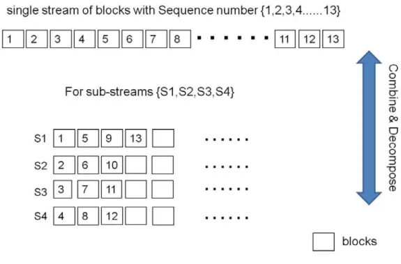
In CoolStreaming, the video streaming is divided into blocks with equal size, and each block is assigned a sequence number to represent its playback order in the streaming. And also divide each video stream into multiple sub-streamings without any coding, in which each node can retrieve any sub-stream independently from different parent nodes. The Figure 3.2-1 is an example of streaming decomposition in CoolStreaming.
Figure 3.2-1 An example of stream decomposition
This subsequently reduces the impact due to a parent departure or failure, and further helps to achieve better transmission efficiency. In the Figure 3.2-1, a video streaming is decomposed into 4 sub-streamings by grouping video blocks according to the following scheme: the i-th sub-stream contains blocks with sequence numbers (4n +i), where n is a non-negative integer, and is a positive integer from 1 to 4. This implies that a node can at most receive sub-streams from 4 parent nodes.
Our proposed streaming format preserver most mechanism of CoolStreaming.. The Figure 3.2-2 shows our streaming format.
Figure 3.2-2 Streaming format in our system
In our system, the smallest streaming unit is block, the video streaming is divided into blocks with equal size; each block size is 1 second. In order to let users can query for watching time-shift streaming in the future, we assign each block sequence number according to the Network Time Protocol (NTP). For example, block sequence number, 20090720172358 represents 2009/7/20 17:23:58. In the Figure 3.2-2, for simply illustration, number 1~110 represents the sequence number of blocks.
The concept of sub-streaming has great assistance in transmission. Each video streaming is divided into 10 sub-streamings without any coding. Differ from CoolStreaming, we need to store sub-streamings for future used in time-shift streaming. Each sub-streaming contains 10 blocks. The Figure 3.2-2 shows in
sub-stream 1, block 1 ~ block 91 are stored as one sub-streaming. Block 101 is the tip block of another sub-stream. And each sub-streaming is represented by the sequence number of its last block. For example, block 92 represents sub-streaming <2, 12, 22, 32, 42, 52, 62, 72, 82, 92>. Furthermore, in our system, in order to simply register procedure; sub-streaming is the smallest unit in storage and transmission. In other words, we store or transmit the whole integrity sub-streaming once time.
At last, we define segment as consecutives blocks in 100 seconds. In other words, each segment contains 10 sub-streaming.
3.3 Storage Architecture
Before introducing our proposed storage architecture, we analyze the feature of our expected P2P steaming system, since the storage architecture makes the following issues involve to each other:
(1) Storage and search policy for time-shift streaming.
(2) The management of live streaming group and time-shift streaming groups.
(3) The transmission architecture of live and time-shift streaming.
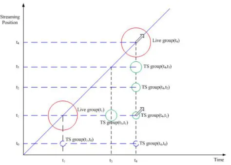
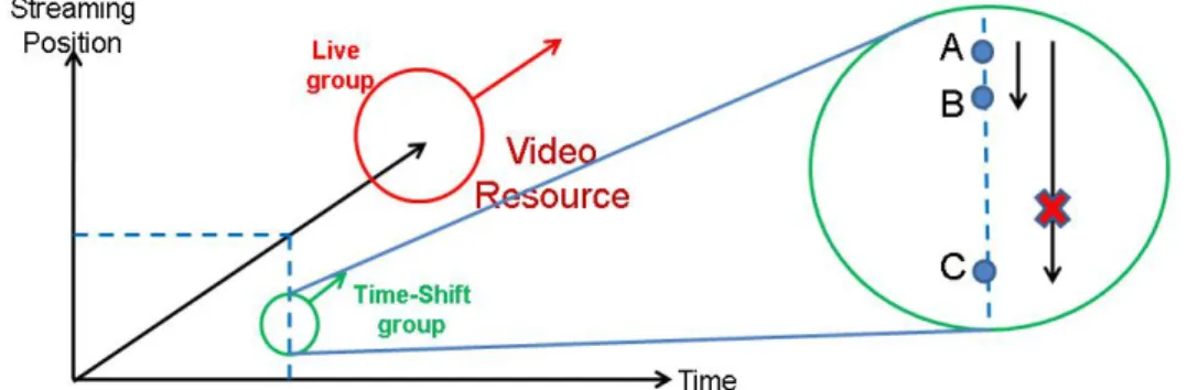
We consider that peers that watch close video content should form a group, because they have great possibility to exchange/share their video data. As the Figure 3.3 reveals, the video content was produced without stopping like the time goes on.
Figure 3.3 Live streaming group and time-shift streaming groups
Furthermore, the Figure 3.3 reveals some time-shift groups and live group (represented by circle). Live group contains all of the users that watch live content; time-shift group gathers some users that their streaming positions are close. Time-shift groups in the same vertical axis are existed at the same time; time-shift groups in the same horizontal axis are watching the same streaming position. All of these groups are dynamic and moving toward 45 degree east of due north in their position, like the arrow in the Figure 3.3.
In general, live group has much more peers than time-shift group. In live streaming, since we can expect there are many peers in live group, peers can easy to and only to share/exchange their live content to each other, therefore in live group, peers only need to contact bootstrap node to get a list of peers as its neighbors.
However, in time-shift streaming, we expect there are few peers in each one time-shift group, which means peers may only receive video content from limited
number of peers. Therefore, it is more difficult to efficiently transmit video content and that’s why collaboration between peers in one time-shift group is important.
3.3.1
Short-team storage and Long-term storage
In our proposed storage architecture, each peer has a short-term storage and a long-term storage. The main purpose of short-term storage is encouraging transmission efficiency by utilizing upload bandwidth of peers in time-shift group, for more efficient in transmission short-term storage is placed in buffer memory. For each peer, no matter what live peers or time-shift peers, peers store they just watched video content in their short-term storage. Here we define size of each short-term storage is consecutives 100 seconds, that is equal to a size of segment, contains 100 blocks, 10 sub-streamings.
In the Figure 3.3.1, peer A, B and C are watching time-shift content. The streaming position of A between streaming position of B is less than 100 seconds. Therefore B can directly and fully receive video content from the short-term storage of A if A has enough upload bandwidth. However, since the streaming position of A and C is over than 100 seconds, C cannot retrieve video content from peer A or B.
The transmission fashion is not only constraint among time-shift peers, time-shift peers can also retrieve time-shift content from the short-term storage of live peers, if streaming positions of time-shift peers within 100 seconds from live streaming.
On the other hand, the main purpose of long-term storage is to backup video content for time-shift peers and tries to maintain longer coverage of video. Obviously, it has great difference from short-term storage; we need an algorithm to decide what should be store in the long-term storage and we place the long-term storage in the disk space. The algorithm will be discussed in the following section.
3.3.2 Operation of Short-term storage
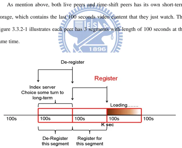
As mention above, both live peers and time-shift peers has its own short-term storage, which contains the last 100 seconds video content that they just watch. The Figure 3.3.2-1 illustrates each peer has 3 segments with length of 100 seconds at the same time.
(1) In the first segment is loading the newly video content;
(2) In the second segment, from (K-100) second to K second, is the newest segment that contains integrity 100 seconds video content. Peer maintains this segment as its short-term storage and registers this segment into index server, so that other peers can reference its short-term storage. We use the Figure 3.3.2-2 to depict the register procedure.
Figure 3.3.2-2. De-registration of short-term storage
In this case, the newest segment contains block 11 ~ block 110, peer only needs to register the last block (block 110) within this segment, that represents the sub-streaming <20, 30, 40, 50, 60, 70, 80, 90, 100, 110> and then index server add remain sub-streamings, sub-streaming 109, sub-streaming 108, sub-streaming 107, sub-streaming 106, sub-streaming 105, sub-streaming 104, sub-streaming 103, sub-streaming 102 and sub-streaming 101.
(3) In the third segment, from (K-200) second to (K-100) second, is the past segment. Peer replaces this segment and does de-register procedure for this segment from index server.
Notice that the three operations: loading, register, de-register, works at the same time and works once in 100 seconds.
3.3.3 Operation of Long-term storage
Streaming packets that store in long-term storage is originated from short-term storage. The long-term storage somehow is a kind of backup storage, letting users can reference time-shift video content. In last section, peers de-register the pass segment, and then we select part of the pass segment turn to as long-term storage. Absolutely, turn the entire pass short-term storage is not ideal method, since we hope to the coverage of time-shift video content as wild as possible.
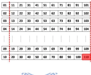
For this reason, in order to prevent peers only concentrating on storing certain of sub-streamings, we assume that the number of replicas for each sub-streaming in one live or time-shift group, 3 is enough. We use the Figure 3.3.3-1 to depict the procedure of turning short-term storage as long-term storage.
Figure 3.3.3-1 Turn short-term storage to Long-term storage
In this case, a peer is going to de-register the pass segment that contains block 1 ~ block 100. The peer only needs to de-register the last block (block 100) within this segment, that represents the sub-streaming <10, 20, 30, 40, 50, 60, 70, 80, 90, 100> and then index server dose the remain de-register procedure, i.e. de-register the sub-streaming 91 ~ sub-streaming 99.
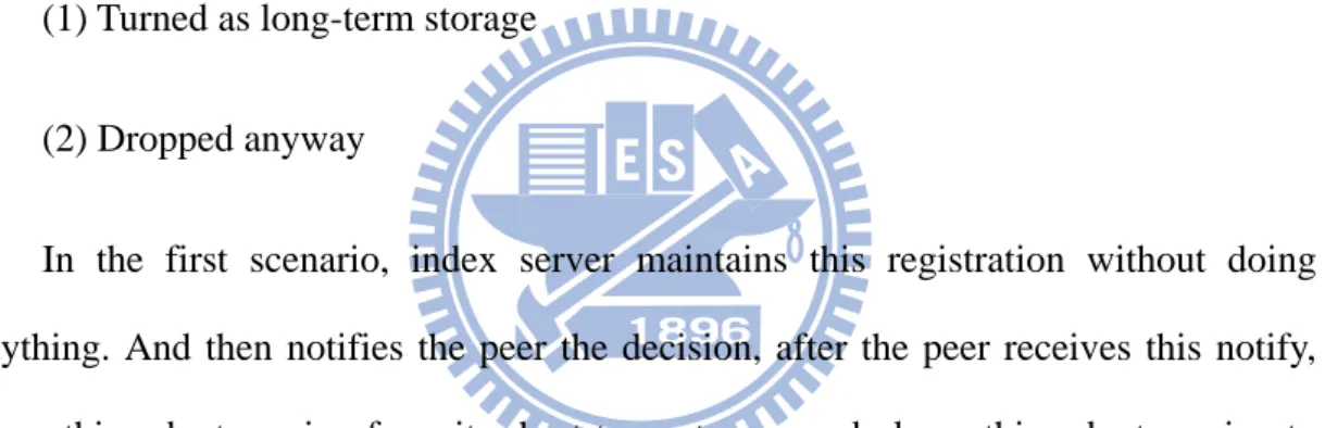
After de-register procedure, index sever judges which sub-streamings among the segment that just de-register should turn as long-term storage. Each sub-streaming will be up against two scenarios:
(1) Turned as long-term storage
(2) Dropped anyway
In the first scenario, index server maintains this registration without doing anything. And then notifies the peer the decision, after the peer receives this notify, drops this sub-streaming from its short-term storage and places this sub-streaming to its long-term storage.
In the second scenario, index server deletes the entry of the sub-streaming, that implies peers cannot reference this sub-streaming from this peer anymore. And then notifies the peer the decision, after the peer receives this notify, simply drops this sub-streaming from its short-term storage.
In the case of the Figure 3.3.3-1, index server preserves sub-streamings 92, 93, 94. The judgment is based on the algorithm, shows as the Figure 3.3.3-2.
Figure 3.3.3-2 Algorithm of long-term storage
N indicates the number of peers in one group. Although we hope to keep the number of replica is more than 3, we don’t want the number of replica too much so that affect the coverage of time-shift video content. When N < 30, index server notifies peers turn whole sub-streaming as long-term storage. When 30 <= N < 100, turns the sub-streaming to long-term based on the number, ID%10. Peers turn the sub-streaming if the peer ID%10 equals to the sub-streaming ID%10. For example, peer 13734 turns the sub-streaming 20090713093154 to its long-term storage. When 100 <= N, except following the last rule, advance turns each sub-streaming with 1/3 probability. For example, peer 13734 turns the sub-streaming 20090713093154 to its long-term storage with 1/3 probability.
Finally, since long-term storage has fixed storage space, we need to perform replacement policy. In our system, each peer counts its number of successful transferred time of each sub-streaming. Obviously, the higher the count number of each sub-streaming, the more replicas is in the system. If there are two or more sub-streamings with the same count number, peers prioritize replacing the former sub-streaming.
coverage of media content. However, the strategy of replacing the highest count number of sub-streaming, maybe meet a situation; all peers maintain less popular media content. This result indicates that there is trade-off between these two issues.
3.4 Live Streaming
In live streaming, our system adopts the mechanism similar to CoolStreaming. In live streaming, peers use buffer map to exchange and share their live content. The buffer map represents the availability of latest bocks in buffer and is composed of two vectors. The first vector records the serial number of the latest received block in each of the sub-stream. For example, since we have 10 sub-streams, the first vector looks like <11, 22, 13, 24, 35, 16, ..., 20>. It represents that the peer has received block with serial number 11 in sub-stream 1, block with serial number 22 in sub-stream 2, and so on.
The second vector specifies which sub-stream to subscribe from other partners. For example, if a peer P wants to subscribe sub-stream 1,2 and 5 from the partner P’, P sends out <1, 1, 0, 0, 1, 0, 0, …, 0> to P’. The “1” represents that P wants to subscribe this sub-stream and “0” stands for that P does not want to subscribe this sub-stream. If a peer wants to subscribe sub-stream N, it simply does this by periodically exchanging BM with the information of the second vector.
After exchanging BM, in content delivery, we adopt hybrid push-pull mechanism to exchange media content among the peers. A peer P pulls at first by subscribing a sub-stream from one of its partner P’ through the second vector of the buffer map. Then P’ will start pushing all the consecutive media blocks of that sub-stream which is available to P. Since a peer needs to pull for all the blocks of each sub-stream from
its partners in the pull mechanism, the hybrid mechanism helps reduce the traffic overhead by simply pulling the first block of each sub-stream. The multiple sub-stream mechanism also helps reduce time used for retrieving media content.
3.5 Time-Shift Streaming
Our system provides time-shift streaming which allows users to watch a live stream with an arbitrary offset at any given time. In our system, the time-shift peer first sends the query message with two fashions.
(1) At first, peers send query message for its desired media contents. The index server then returns a list of peers having the specific contents, and the requesting peer will try to add itself as a member in a certain time-shift group.
(2) If the peer is in one time-shift group, it queries its desired media content by using gossip search.
Time-shift groups in our system actually are organized by gossip members of peers. Section 3.5.1 introduces gossip target selection: section 3.5.2 introduces gossip search.
3.5.1
Gossip Target Selection
A time-shift peer A queries the desired block from the index server at first with specific time T. The index server then queries the nearest block equal to T or after T, and finds a list of peers having that specific block. Since lots of peers may be found as the gossip targets and too many gossip targets may induce too much traffic overhead due to the exchange of gossip messages. So we design how to select gossip target
based on the inference - the nearer the time a peer watches from one peer, the higher probability it has the blocks it will need in the near future. We can use the registration time to represent the time that peers watched the video content.
Assume peer A is the newly time-shift peer and peer B, C, D, E and F have the specific media block that A queries. The Figure 3.5 shows the block registration time of each peer. The order of registration time from the nearest to the most far compared to current time is B, C, D, E and F.
Figure 3.5 Sub-streaming registration time of each peer
Since the media block of B has the nearest registration time compared to current time, B has the most probability that it watches this media block most recently. Moreover, B may have the short-term storage that A will need in the near future. So the index server first adds B into the list that will be sent to A. Then the index server adds C, D and E whose registration time of that block are no more than 100 seconds compared to the nearest peer B since we think the peers (ex: F) with registration time of the block more than 100 seconds compared to B may not watch this media block recently and may not have the blocks A will need with higher probability in the near future. So the list now contains B, C, D and E. Then the index server sends the list to peer A and peer A adds the peers in the list as its gossip targets.
3.5.2 Gossip
Search
After peer P locates the desired block from the index server, suppose a list with N peers having this block is sent back from the index server, P first finds the peer having short-term blocks indicating in the list. P sends the request message to one of the peers having the short-term blocks. These requested peers then compute their own residual upload bandwidth and request achieve rate. The one with the highest residual upload bandwidth pushes all the short-term blocks it owns to P. If two or more peers have the same residual upload bandwidth, choose the one with the highest request achieve rate since it could handle the request with higher probability. If no peer having short-term blocks is found, P then performs gossip search.
P sends request message (with TTL = 2 and timeout TT) to all its gossip targets. Suppose N’ peers having this block are found. These N’ peers send back reply message with residual upload bandwidth and request achieve rate to P. P receives the reply messages and records the information on it. Then P chooses the one (P’) with the highest residual upload bandwidth within all N’ peers and P’ starts to push all the consecutive blocks it owns to P. If two or more peers have the same residual upload bandwidth, choose the one with the highest request achieve rate.
If no peer having the desired block is found in the gossip search, P queries the index server directly since none of its gossip targets has the block.
Chapter 4
System Implementation and Analysis
There are three components in our system, a bootstrap server, an index server and streaming peers, each with different functionalities. The bootstrap server and the index server are implemented with Java socket. Each of them creates a thread to serve a connecting peer individually.
4.1 Index server
Interaction between peers and index server is an important part in our system. Peers register to by sending the registration message, shows as the Figure 4.1-1; we depict these six columns one by one.
Figure 4.1-1 Registration message
1. This column is fixed, notify index server to deal with remain columns. 2. Each peer fills its ID in this column.
3. Each peer fills the sequence number of block that it wants to register. 4. Mark its registration time.
5. Fill the sequence number of the last block in the sub-streaming that peers want to replace and de-register from its long-term storage.
6. Fill the sequence number of the last block in the pass segment that peers want to de-register from its short-term storage.
Index server sends feedback message to peers after it received registration message, using the fourth column, “time”, to count how many peers has been register for this sub-streaming within 100 seconds. The result of counting is the “N” as we mentioned in section 3.3.3. And then index server judges which sub-streaming should be turned into long-term storage based on the “N”.
The feedback message only informs peers should turn which sub-streamings from short-term storage to long-term storage. Figure 4.1-2 is the feedback message format.
Figure 4.1‐2 Feedback message
Following the example of the Figure 3.3.3-1, index server sends feedback
message as following: <not store 91, store 92, store 93, store 94, not store 95, not store 96, not store 97, not store 98, not store 99, not store 100>.
4.2 System analysis
In our system, we use long-term storage to provide video content for user watching time-shift video. Therefore, the coverage range of time-shift video content is an important issue.
We can use the Figure 4.2 (a) and the Figure 4.2 (b) to analyze the algorithm in our index server, which already mentioned in section 3.3.3. These two figures are based on the same condition: (1) each peer has long-term storage with 200 MB. (2) All peers are watching live content, and without any peers request time-shift content, since we want to simplify the replacement policy.
We compare our algorithm with “store whole segment” and “store whole sub-streaming”.
“Store whole segment” means turn whole short-term storage to long-term storage without any alternation. “Store whole segment” means we turn each sub-streaming based on the ID of the peer and the ID of the sub-streaming, but without considering the number of users.
Figure 4.2 (a) Storage range of long-term storage
Figure 4.2 (b) Number of replica of block
The Figure 4.2 (a) indicates the coverage range of time‐shift video content; the Figure 4.2 (b) indicates the number of replicas of each sub‐streaming. The Figure 4.2 (a) illustrates that our algorithm can increase the storage range with increasing of number of users, the other two methods can only maintain the fixed storage range. However, in the Figure 4.2 (b), the other two methods show the replicas are increasing violently with increasing of number of peers, instead of increasing slowing by adopting our algorithm. This is a trade‐off problem, we consider it is worth to barter the number of replicas for the storage range, since we believe lengthening the storage range is more important, besides the number of replicas is still growing with the number of peers, although it grows slowly.
Chapter 5
Conclusions and Future Work
P2P streaming services today can be classified into two individual categories – P2P live streaming and P2P VoD streaming. A user watching live streaming may want to watch the previous video contents, i.e., the video contents just played 30 minutes ago or an hour ago. However, few P2P streaming systems support both live streaming and time-shift streaming at the same time nowadays according to our literature search, and most of them are just prototypes and have not been implemented yet.
In this thesis we propose an effective storage policy for P2P time-shift streaming. Each peer has its own short-term storage and long-term storage. The short-term storage is continuous video content that just been played back at the peer. The long-term storage stores segments of media content for time-shift viewers. We lengthen the coverage range of time-shift media content as far as possible by the process of turning short-term to long-term storage and the storage replacement policy. However, in our system, most computations are handled by the index server. In the future work, the index servers can be replaced by a DHT structure implemented in every peer and thereafter we can query and form groups without the help of dedicated servers. A live and time-shift streaming service can be implemented in a pure P2P network architecture in the future.
References
[1]Napster, http://free.napster.com/ [2] ezPeer, http://web.ezpeer.com/ [3] eDonkey, http://www.zeropaid.com/edonkey/ [4] eMule, http://www.emule.com/ [5] KaZaa, http://www.kazaa.com/ [6] BitTorrent, http:// www.bittorrent.com/ [7] Skype, http://www.skype.com [8] PPStream, http://www.ppstream.com/ [9] pplive, http://www.pplive.com/[10] F. V. Hecht, T. Bocek, C. Morariu, D. Hausheer, B. Stiller, “LiveShift: Peer-to-peer live streaming with distributed time-shifting,” in 8th International Conference on Peer-to-Peer Computing (P2P'08)
[11] S. Deshpande, J. Noh, “P2TSS: Time-shifted and live streaming of video in peer-to-peer systems,” Multimedia and Expo, 2008 IEEE International Conference on [12] Diego Gallo, Charles Miers, Vlad Coroama, and Tereza Carvalho, “A Multimedia Delivery Architecture for IPTV with P2P-based Time-Shift Support,” in Consumer Communications and Networking Conference, 2009. CCNC 2009. 6th IEEE
[13] Y. H. Chu, S. G. Rao, and H. Zhang, “A Case for End System Multicast,” IEEE J. Sel. Areas Commun., vol.20, pp. 1-12, Oct. 2002.
[14] Z. Liu, H. Yu, D. Kundur, M. Merabti, “On Peer-to-Peer Multimedia Content Access and Distribution” in Proc. International Conference on Multimedia and Expo, pp.557-560. Jul. 2006.
[15] M. Castro, P. Druschel, A.M. Kermarrec, A. Nandi, A. Rowstron, A. Singh, “Splitstream: High-bandwidth content distribution in a cooperative environment,” in Proc. nineteenth ACM symposium on Operating systems principles, pp. 292-303. Oct. 2003.
[16] V. N. Padmanabhan, H. J. Wang , P. A. Chou, K. Sripanidkulchai, “Distributing streaming media content using cooperative networking,” in Proc. 12th international workshop on Network and operating systems support for digital audio and video, pp. 177-186. Apr. 2002.
[17] X. Zhang, J. Liu, B. Li, and Y.-S.P. Yum,” CoolStreaming/DONet: a data-driven overlay network for peer-to-peer live media streaming,” in Proc. 24th Annual Joint Conference of the IEEE Computer and Communications Societies, pp. 2102-2111, Mar. 2005.
[18] SopCast, http://www.sopcast.com/
[19] Y. Guo, K. Suh, J. Kurose, and D. Towsley, “P2Cast: peer-to-peer patching scheme for VoD service,” WWW, May 2003.
[20] T. Do, K. A. Hua, and M. Tantaoui, “P2VoD: providing fault tolerant
video-on-demand streaming in peer-to-peer environment,”IEEE ICC, vol. 3, June 2004.
[21] C. Dana, D. Li, D. Harrison, and C. Chuah, “Bass: Bittorrent assisted streaming system for video-on-demand,” in International workshop on multimedia signal processing (MMsP), 2005.
[22] “Joost”, http://www.joost.com/. [23] “UUSee”, http://www.uusee.com/. [24] “GridCast”, http://www.gridcast.cn/.