國
立
交
通
大
學
電子工程學系 電子研究所碩士班
碩
士
論
文
適用於高速移動的無線都會網路正交分頻多工
空時區塊碼干擾消除器之設計
Design of OFDM STBC Interference Canceller for
High-Mobility Wireless Metropolitan Area
Network
研 究 生:張為凱
指導教授:周世傑 博士
I
適用於高速移動之無線都會網路空時區塊碼正
交分頻多工干擾消除器設計
Design of STBC OFDM Interference Canceller for High-Mobility
Wireless Metropolitan Area Network
研究生: 張為凱
Student: Wei-Kai Chang
指導教授: 周世傑 博士
Advisor: Dr. Shye-Jye Jou
國 立 交 通 大 學
電 子 工 程 學 系
碩 士 論 文
A Thesis
Submitted to Department of Electronics Engineering & Institute of Electronics College of Electrical and Computer Engineering
National Chiao Tung University in Partial Fulfillment of the Requirements
for the Degree of Master in
Electronics Engineering
October 2010
HsinChu, Taiwan, Republic of China
II
適用於高速移動之無線都會網路空時區塊碼正
交分頻多工干擾消除器設計
研 究 生 : 張 為 凱 指 導 教 授 : 周 世 傑 博 士
國立交通大學
電子工程學系 電子研究所碩士班
摘要
近年來,時空區塊碼(space-time block code; STBC)已被證實可以提供高編碼率 及好的效能。在多根傳輸天限的正交多頻分工(orthogonal frequency-division multiplexing; OFDM ) 的 系 統 應 用 中 , 時 空 區 塊 碼 可 增 加 分 集 增 益 (diversity gain) 而 且 也 被 IEEE802.16e/m 規格支援。但是時空區塊碼對於單一編碼字元時間間隔內的通道時域變 化非常敏感,這些變化將使得單一邊碼字元內的符元資料互相干擾;而且時變性多路徑 通 道 也 會 在 正 交 多 頻 分 工 系 統 的 次 載 波 間 引 發 正 交 多 頻 分 工 次 載 波 間 干 擾 (Inter-carrier Interference;ICI)效應。這些干擾雜訊會破壞空時區塊碼與正交分頻 多工系統結合之系統應用(STBC-OFDM systems)的性能,因此我們必須一種空時區塊 碼 正 交 分 頻 多 工 干 擾 消 除 器 才 能 在 無 法 取 得 詳 細 的 通 道 狀 態 資 訊 ( channel state information; CSI)的狀況下達到更好的效能。 這篇論文將提出一個可適用於高速移動環境中兩根傳送天線與一根接收天線 之空時區塊碼與正交分頻多工系統結合之系統的干擾消除器。此空時區塊碼正交分頻多 工干擾消除器的設計是基於一套現存 IEEE802.16e 規格的接收器,但是它也可以輕易的 修改為 IEEE802.16e 規格。設計的目標是在高達時速 360 公里的移動環境中提供效能的
III
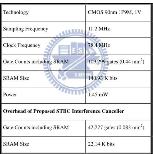
改善,我們將提出的設計與一套被研究過的兩階段通道估測器(two-stage channel estimator)搭配來展示效能,在時速 240 及 360 公里、訊噪比(signal to noise ratio;SNR) 高於 15dB、16 正交振幅調變(16 quadrature amplitude modulation; 16-QAM)的環 境中可減少位元錯誤率(bit error rate; BER)超過 2 倍。我們以 90 nm CMOS 製程實 現此干擾消除器設計。總共需要 42,277 個邏輯閘,在 78.4MHz 的操作頻率與 1 V 工作 電壓下,其功率消耗為 1.45 mW。干擾消除器設計中大約 61%的邏輯閘可以與現有的兩 階段通道估測器共用,額外的負擔只占原先兩階段通道估測器的 4.9%
IV
Design of STBC OFDM Interference Canceller for High-Mobility
Wireless Metropolitan Area Network
S t u d e n t : We i - K a i , C h a n g A d v i s o r : D r. S h yh - J y e , J o u
Department of Electronics Engineering & Institute of Electronics
National Chiao Tung University
Abstract
In recent years, space time block code (STBC) has been shown to give high code rate and good performance. It is suggested to be applied in an orthogonal frequency division multiplex (OFDM) system since OFDM system with multiple antennas can provide better communication performance by exploiting transmit diversity and it was also supported by IEEE 802.16e/m standard. Nevertheless, STBC is sensitive to the temporal channel variation inside one code word which results in the symbols inside one codeword interferes with each other. Also, time-varying multipath channel introduces intercarrier interference (ICI) among OFDM subcarriers. These interference noises degrade STBC-OFDM system performance. Hence, an STBC interference cancellation scheme is required for better performance when the detailed channel statistics information (CSI) variation is unavailable.
This thesis proposes an STBC interference canceller for any STBC-OFDM systems with two transmit antenna and one receive antenna in mobile environment. The proposed STBC interference canceller is applied in an existed IEEE802.16e STBC-OFDM receiver and can easily be adapted into IEEE802.16m STBC-OFDM receiver, too. The proposed design aims to provide performance improvement under the vehicle speed up to 360 km/hr. The
V
performances have been demonstrated through the simulation of the proposed design with a previously proposed two-stage channel estimator. At vehicle speed of 240 and 360 km/hr and signal to noise ratio (SNR) over 15dB for 16 quadrature amplitude modulation (16QAM), the proposed design can provide more than 2 times bit error rate (BER) improvement. The proposed design is implemented in 90 nm CMOS technology. The gate count is 42,277 and the power dissipation is 1.45 mW at 78.4 MHz operation frequency from a supply voltage 1V. About 61% gates of our proposed STBC interference canceller are shared with the existed two-stage channel estimator design, and the overhead is only 4.9%.
VI
誌 謝
隨著這份研究的完成我獲得了交大電子工程碩士學位,研發替代役也順利應徵上人 人稱羨的聯發科技,離鄉背井六年的求學生涯就此告一段落。這段旅途的圓滿結局泰半 得歸功於一路上諸多貴人幫助,因為要感激的人實在太多了,光用「謝天」二字籠統帶 過會經不起良心譴責而輾轉難眠。 首先要感謝我的指導老師周教授世傑先生,感謝他在 2008 年碩士班推甄時接受我 的毛遂自薦,並且提供我優渥舒適的研究環境和研究方向,讓我得依自己的興趣精進通 訊演算法技能並同時兼顧電路設計的基本功夫。在學業課題外,周老師的教誨也啟發我 讓我以更積極、樂觀的態度去體驗和學習待人接物的道理。 接著要感謝帶領我研究的 MOMO 學姊,多虧學姊胼手胝足建立了通道估計的電路 硬體及完善的軟體模擬平台,我的構想才得以發揮與驗證;在我研究遭遇瓶頸搜索枯腸 時,學姊也願意犧牲時間幫忙我除蟲和傷腦筋。 也謝謝諸位實驗室的前輩們,小肥、小胖、儷蓉、大大、麥哥、阿賢、銘銓、范 姜、嘉文、亦緯、代暘、淳淳哥等,學校裡各式各樣難解的疑難雜症在他們熱心幫忙下 都可迎刃而解。也感謝同儕朋友和學弟妹的情義相挺,以樂、TMC、雅雪、烏克蘇、福 鈞、育瑞、紹丞、佳怡、Juii 等。 最後還要感謝我最親愛的家人以及女友恩立長久以來的照顧與支持,讓我可以徜 徉書海醉心研究而無後顧之憂,謹將所有的成就和榮耀獻給他們。 張為凱 謹誌於 新竹 2010 年 10 月VII
Contents
Chapter 1 Introduction ... 1
1.1 Overview of IEEE 802.16e/m OFDM systems ... 1
1.2 Motivation ... 2
1.3 Thesis Organization ... 3
Chapter 2 Interference of STBC-OFDM Systems in Wireless Mobile Environment ... 4
2.1 STBC-OFDM Systems under Quasi-Static Channel... 4
2.1.1 STBC Encoding ... 5
2.1.2 STBC Decoding ... 5
2.2 Time-variant Multipath Channel and ICI Effect of OFDM Systems ... 7
2.2.1 Time-variant Multipath Channel ... 7
2.2.2 ICI effect ... 10
2.3 Interference Noise of STBC-OFDM Systems ... 11
2.4 Proposed Decoding Flow ... 15
Chapter 3 STBC OFDM Interference Cancellation Algorithm ... 17
3.1 802.16e STBC OFDM System Specification ... 17
3.1.1 Frame Structure ... 17
3.1.2 Preamble Format ... 18
3.1.3 Pilot Modulation ... 19
3.1.4 Differences Between 802.16e and 802.16m ... 20
3.1.5 Major Parameters and Design Targets ... 21
3.2 Overview of DFT-based Channel Tracking Estimation ... 24
VIII
3.2.2 Channel Estimator Architecture ... 27
3.3 Co-carrier Interference modeling ... 29
3.4 Inter-carrier Interference modeling ... 31
3.4.1 Polynomial Modeling of Channel Variation ... 31
3.4.2 Simplified Frequency Domain Channel Matrix ... 34
3.4.3 Pilot ICI Component ... 36
3.5 Joined Interference Cancellation Algorithm... 37
3.6 Simulation Results ... 40
3.6.1 Proposed Algorithm with Perfect Channel Estimation ... 40
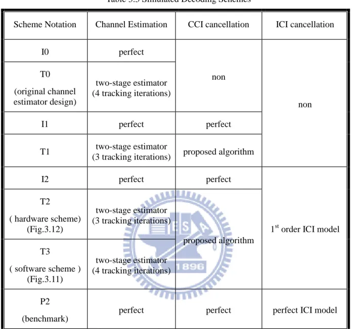
3.6.2 Proposed Decoding Scheme With Two-Stage Channel Estimator ... 44
3.7 Summary ... 52
Chapter 4 Architecture Design and Circuit Implementation ... 53
4.1 Design Overview ... 53
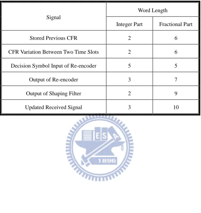
4.2 Word Length Optimization ... 58
4.3 STBC Re-encoder Block ... 61
4.4 Interference Shaping Filter Block ... 63
4.5 Simulation Results ... 65
4.6 Design Results ... 70
Chapter 5 Conclusion ... 72
IX
List of Figures
Fig.2.1 Conventional STBC-OFDM system with quasi-static channel ... 4
Fig2.2 Zero-th order Bessel function of the first kind... 9
Fig.2.3 Conventional STBC-OFDM system with time-variant channel ... 11
Fig.2.4 Proposed STBC-OFDM system with STBC interference canceller ... 16
Fig. 3.1 An OFDM frame structure in TDD mode ... 18
Fig. 3.3 Frame format ... 23
Fig.3.5 Relationship between CFR estimations in time domain ... 29
Fig.3.6 The diagram of an observation block ... 32
Fig.3.7 BER performances versus decoding iteration number for 16QAM at vehicle speed 360 km/h and 240 km/hr ... 41
Fig.3.8 BER performances versus decoding iteration number for QPSK at vehicle speed 360 km/h and 240 km/hr ... 42
Fig.3.9 BER performances versus decoding iteration number for 16QAM at vehicle speed 360 km/h and 240 km/hr ... 43
Fig.3.10 BER performances versus decoding iteration number for QPSK at vehicle speed 360 km/h and 240 km/hr ... 43
Fig.3.11 Proposed decoding scheme for software simulations (software version) ... 45
Fig.3.12 Proposed decoding scheme for hardware implementation (hardware version) . 46 Fig.3.13 BER performance versus Eb/No for 16QAM at vehicle speed 240 km/hr ... 50
Fig.3.14 BER performance versus Eb/No for 16QAM at vehicle speed 360 km/hr ... 50
X
Fig.3.16 BER performance versus Eb/No for QPSK at vehicle speed 360 km/hr ... 51
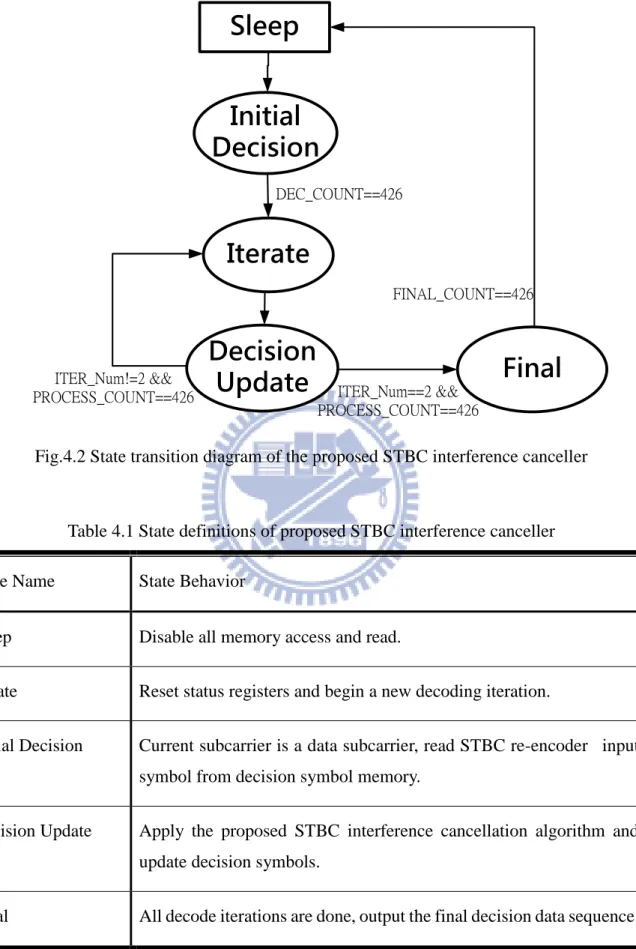
Fig.4.2 State transition diagram of the proposed STBC interference canceller ... 56
Fig.4.3 Architecture of the proposed STBC interference canceller ... 57
Fig.4.4 Output SNR versus different fractional part word lengths for the shaping filter output ... 59
Fig.4.5 STBC re-encoder circuit design ... 62
Fig.4.6 Design of shaping filter circuit design of (a) the first transmit antenna branch and (b) the second transmit antenna branch ... 64
Fig.4.7 BER performance versus Eb/No at vehicle speed 240 km/hr ... 66
Fig.4.8 BER performance versus Eb/No at vehicle speed 360 km/hr ... 66
Fig.4.9 Improved performance ratio of 16QAM at vehicle speed 240 km/hr ... 68
Fig.4.10 Improved performance ratio of 16QAM at vehicle speed 360 km/hr ... 68
Fig.4.11 Improved performance ratio of QPSK at vehicle speed 240 km/hr ... 69
Fig.4.12 Improved performance ratio of QPSK at vehicle speed 360 km/hr ... 69
XI
List of Tables
Table 2.1 Transmit symbols of Alamouti STBC encoding scheme ... 5
Table 2.2 Frequency domain channel matrices of an STBC code word ... 11
Table 3.1 802.16e and 802.16m comparison ... 21
Table 3.2 Major parameters of proposed STBC-OFDM system ... 22
Table 3.3 Simulated Decoding Schemes ... 48
Table 4.1 State definitions of proposed STBC interference canceller ... 56
Table 4.2 Word lengths of several key signals in the proposed STBC interference canceller ... 60
1
Chapter 1 Introduction
1.1 Overview of IEEE 802.16e/m OFDM systems
Wireless Metropolitan Area Network (WiMAN), allowing end-users to travel throughout a hot zone cell without losing connectivity, has been an very important technique in wireless communication. The services provide portability and mobility to make users more convenient to access information. For the high quality service, the channel capacity seems more important for WiMAN, therefore, the error correcting capability is a great issue in WiMAN. WiMAN is defined by IEEE 802.16 Working Group on Worldwide Internet access (BWA) standards and commercially known as Worldwide Interoperability for Microwave Access (WiMAX) which defines broadband Internet access from fixed or mobile devices via antennas.
IEEE 802.16e standard [1] was released in 2005 and is often referred to as mobile WiMAX. It is an extension of IEEE802.16-2004 for providing high data rate transmission and mobility of WMAN. It enables mobile speed up to 120 km/hr, but also backward compatible to support the fixed mode in IEEE 802.16-2004. Operation in mobile mode is limited to the license bands between 2-6 GHz. It is based on an OFDMA technique to support multiple access scheme and multiple-input multiple output (MIMO) systems over multipath fading channels.
IEEE 802.16m standard [2] is an updated version of IEEE 802.16e. It is also fully backward compatible to support the older IEEE 802.16 standards, and targets to attract new operators that starts the deployment from 2012. Note that the enabled mobile speed is increased to 350 km/hr. The other major differences between 802.16e and 802.16m are discussed in Section3.1.4.
In this thesis design and implementation of STBC interference canceller for high mobility WiMAN is proposed. The implementation uses IEEE802.16e as a test vehicle and can also be adopted in IEEE802.16m application.
2
1.2 Motivation
IEEE 802.16e/m systems effectively provide wireless transmission of data using a variety of transmission modes from point-to-multipoint links to portable and fully mobile internet access. The research of IEEE 802.16e/m systems have gained more and more interest and become the world wide topic. However, in mobile wireless communication, the channel often varies rapidly, which results in a large Doppler spread, particularly when the mobile station (MS) moves at a vehicular speed. A fundamental phenomenon that makes credible wireless transmission expensive and difficult is time-varying multipath channels. In order to improve the transmission quality in fast and selective fading channels, transmit diversity is an effective technology for reducing fading effect in mobile wireless communication, especially when receive diversity is expensive or impractical to acquire.
In recent years, space time block code (STBC) has been shown to give high code rate and good performance. It is suggested to be applied in an OFDM system since OFDM system with multiple antennas can provide better communication performance by exploiting transmit diversity and it was also supported by IEEE 802.16e/m standard. Nevertheless, STBC is sensitive to the temporal channel variation inside one code word which results in the symbols inside one codeword interferes with each other. Also, time-varying multipath channel introduce intercarrier interference (ICI) among OFDM subcarriers. These interference noises degrade STBC-OFDM system performance. Hence, an STBC interference cancellation scheme is required for better performance when the detailed channel statistics information (CSI) variation is unavailable.
In this thesis, we focus on the design and development of an STBC interference canceller applied in an IEEE 802.16e down link baseband receiver. The proposed algorithm and hardware architecture are proposed to present an efficient and low-overhead solution for any conventional STBC-OFDM system.
3
1.3 Thesis Organization
The rest of this thesis is organized as follows. Chapter 2 introduces the principle of STBC OFDM and formulates its interference noise components introduced by time-variant channels. Chapter 3 presents the algorithm design and its simulation results. The goal of the proposed design is to integrate with an recently published two-stage STBC-OFDM channel estimator [3] to improve system performance at high-mobility and high-QAM constellation applications. In Chapter 4, an efficient architecture is provided to keep high performance without increasing hardware overhead. Finally, Chapter 5 is the conclusion.
4
Chapter 2 Interference of STBC-OFDM Systems
in Wireless Mobile Environment
MIMO-ODFM technique employs multiple antennas at the transmitter or receiver to increase diversity gain and improve system performance without additional bandwidth or transmit power. But in modern wireless mobile applications, receiver diversity is considered too costly to be implemented. The concept of space-time block code (STBC) provides a very efficient method to exploit transmit diversity. In recent years, STBC-OFDM has been adopted in 802.16e/m to support high speed applications.
STBC requires the channel between each transmit-receive antenna pair to be constant over the symbol periods inside 1 code word. However, this assumption rarely holds in highly mobile applications. Time domain channel variation results in several kinds of interference noise during decoding and impact system performance. In this chapter, we will derive these interference noises and demonstrate their effects on system performance through simulation.
2.1 STBC-OFDM Systems under Quasi-Static
Channel
We begin this chapter with the assumption that the channels do not vary over a STBC code word period, it is also known as “quasi-static condition”. Fig.2.1 is a conventional OFDM system having transmit diversity.
STBC Encoder Channel Estimator STBC Decoder IFFT IFFT FFT F X * S X * F X XS F X S X (1) H (2) H F X S X (1) M M(2) R
5
2.1.1 STBC Encoding
Among various STBC scheme that has been studied, Alamouti coding scheme is the most popular and practical one [4]. This scheme requires 2 transmit antenna and 1 receive antenna as shown in Fig.2.1. Each block code word occupies the length of 2 symbol interval, or 1 “time slot.” 2 OFDM symbols, and , are encoded and transmit from different antenna in the manner described in Table 2.1, where is the subcarrier index , N is the total number of subcarriers ,and the superscript * stands for complex conjugate.
Table 2.1 Transmit symbols of Alamouti STBC encoding scheme Transmit Antenna
1st Antenna 2nd Antenna
One time slot duration 1st Symbol Interval XF XS 2nd Symbol Interval X*S * F X
2.1.2 STBC Decoding
The channel frequency response between the first transmit antenna and receive antenna at the
ts
-th time slot is denoted as H [ ](1)ts k and the other one is denoted as(2)
H [ ]ts k . Within this
time slot, the 1st and 2nd received OFDM symbols, Rts[1, ]k and Rts[1, ]k , can be expressed as
(1) (2) (1) * (2) * [1, ] H [ ] H [ ] [1, ] [2, ] H [ ] H [ ] [2, ] ts ts ts F S ts ts ts ts S F ts R k k X k k X k Z k R k k X k k X k Z k (2.1)6
and Zts[1, ]k and Zts[2, ]k are the uncorrelated additive white Gaussian noise (AWGN) with zero-mean and variance
z2.To demonstrate decoding process clearly, we reformulate (2.1) as below.
(1) (2) * * * (2) (1) * ts ts H [ ] H [1, ] [1, ] [2, ] H - H [2, ] X[ ] Z [ ] Y A ts ts ts F S ts ts ts ts k k R k X k Z k X k R k k k Z k k k k k (2.2)To perform simple Alamouti decoding, we multiplying AtsH
k with received signals and the 2symbols in X[ ]k are decoupled from each other:
ts ts ts ts ts 2 2 (1) (2) A Y A A X [ ] A Z [ ] [ ]X [ ] A Z [ ] [ ] H [ ] H [ ] H H H ts ts ts ts H ts ts ts ts ts k k k k k k k k k k k k k k (2.3)where superscript “H” stands for Hermitian transpose. Based on the latest estimated channel
frequency response M(1) and M(2), the decision of 2 transmitted symbol can be made
independently by the following equations
* * (1) (2) * * (2) (1) 2 2 (1) (2) 1 [ ] [ ] [1, ] [ ] [2, ] [ ] 1 [ ] [ ] [1, ] [ ] [2, ] [ ] [ ] [ ] [ ] F ts ts ts ts ts S ts ts ts ts ts ts ts ts X k M k R k M k R k k X k M k R k M k R k k k M k M k (2.4)7
2.2 Time-variant Multipath Channel and ICI Effect of
OFDM Systems
2.2.1 Time-variant Multipath Channel
In mobile wireless environment, multipath channels are usually time-variant. Although the degree of channel variation over an sampling period decrease as data rate becomes higher, the time variation of a fading channel over an OFDM symbol interferes the orthogonality between subcarriers. This undesired effect in known as intercarrier interference (ICI). As the vehicle speed increases, it introduces Doppler spread and increases the error floor.
Without loss of generality, we consider an single-input-single-output (SISO) OFDM
system that has only one transmit antenna. Let X k be the data symbol transmitted through
the k-th subcarrier for an OFDM symbol. Then after N-point inverse fast Fourier transform
(IFFT) modulation and appending cyclic prefix with length Ng, the transmitted time domain
data symbol at time q is denoted as
2 1 0 1 [ ] [ ] , , 1, , 1 kq N j N g g k x q X k e for q N N N N
(2.5)Assuming the multipath fading channel between the i-th transmit antenna and the receive
antenna is made of L discrete paths, the received signal can be expressed as [4].
1 [ ] [ ] [ ] [ ] L l g g l r q h N q x q l z N q
(2.6)where h bl[ ] and z b[ ] represents the complex path gain for the -thl path and AWGN at time b respectively. By removing the cyclic prefix and taking the fast Fourier transform (FFT), the demodulated signal in frequency domain is given by
8 2 ( ) 1 1 2 0 1 0 1 0 1 [ ] [ ] [ ] [ ] H[ , ] [ ] [ ] l q m k m N L N j j N N l m l q N m R k X m h q e e Z k N k m X m Z k
(2.7) 2 ( ) 1 2 1 0 1 [ , ] l [ ] m q m k L j N j N N l l q H k m e h q e N
(2.8)where H k m[ , ] represents the frequency domain channel coefficient between the m-th
transmitted subcarrier to the k-th received subcarrier, Z k[ ] is the FFT of AWGN,
l denotesthe delay of the l -th path ,and m0,1, 2, ,N-1.
The significance of channel variation can be measured as the correlation of 2 channel impulse response samples separated by an given time , defined as
E h q
l[ ] [ ]h ql*
.According to the studies of [5], the correlation function and vehicle speed has the following relation
0
2 d
E d c c J f V f f V (2.9)where f is the Doppler frequency, d VE represents vehicle speed, V stands for light speed, c
c
9
Fig2.2 Zero-th order Bessel function of the first kind
And the spectral density of
is the renowned “Jakes model”. It can be observed fromFig.2.2 that given a fixed carrier frequency, the absolute value of
decreases whenvehicle speed increases. Therefore, the temporal channel variation becomes more random and abrupt in high speed environment. Rapid temporal channel variation results in Doppler spread
effect in frequency domain described by (2.10), where PJ
f stands for the power spectraldensity at frequency f .
2 1 1 , if 1 0 , elsewhere d d J d f f f f P f f (2.10)In OFDM systems, Doppler spread effect causes ICI between neighboring subcarriers. The performance loss due to the ICI becomes significant as the carrier frequency, OFDM block interval, and vehicle speed increase.
10
2.2.2 ICI effect
The channel matrix H can be simplified as
1 2 0 2 ( ) 1 2 1 0 0
[ ]
; if
[ , ]
1
[ ]
; if
l l k L j N l m q m k L j N j N N l l q lk e
k
m
H k m
e
h q e
k
m
N
h
(2.11) 1 01
[
]
N l g q lh N
q
N
h
(2.12)where hl is time average of the l -th complex path gain over the effective duration of an
OFDM symbol interval. It should be note that the diagonal terms of H is the FFT of hl, and
is equivalent to our desired channel frequency response. Those off-diagonal terms stands for the coupling coefficient between different subcarriers which results in ICI effect. For better comprehension, (2.7) can be rewritten as
1 0
[ ]
H[ , ] [ ]
H[ , ] [ ]
[ ]
ICI term
N m m kR k
k k X k
k m X m
Z k
(2.13)If our channel is time invariant, complex path gain at any time within the effect duration of an OFDM symbol is equal to hl, and it is easy to show that the off-diagonal terms of H
becomes zero.
2 ( ) 2 ( ) 1 1 0 0[
]
0
1
1
[ ]
0
[ , ]
0
l g q m k q m k N j N j N N l q q lh N
p
p
p
N
hl
h q e
e
k
m
N
N
H k m
k
m
h
(2.14)11
This implies that there is no ICI for time-invariant channel, and the received signal contains only the multiplicative distortion and AWGN. They can be easily dealt with one-tap equalizer
and MAP detector. More detailed interpretations of h and l H are provided in [4].
2.3 Interference Noise of STBC-OFDM Systems
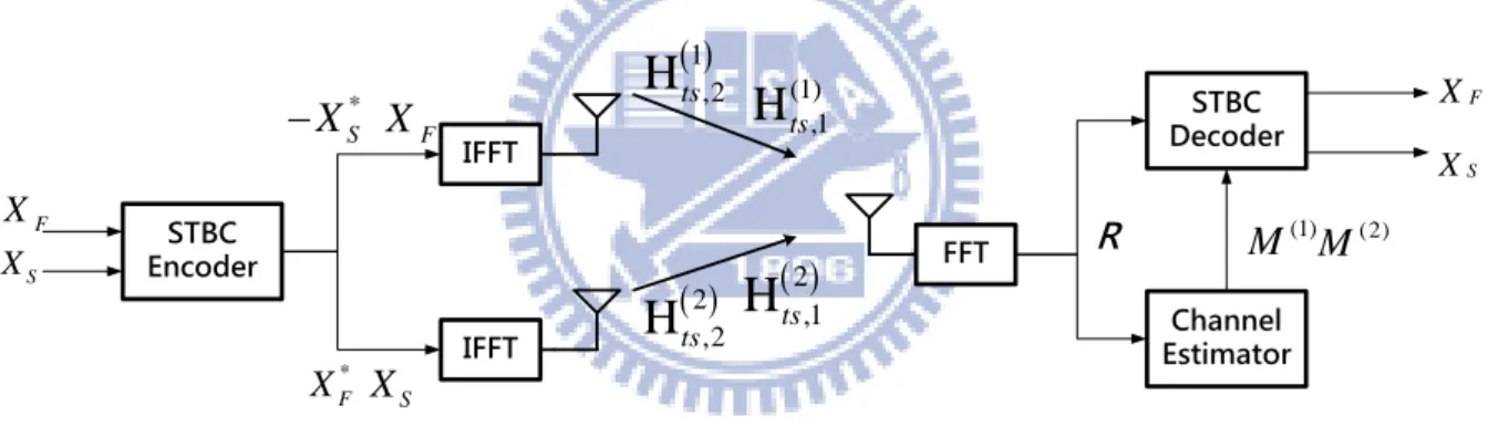
For time-variant channels, channel variation between OFDM symbols become significant, and the “quasi-static condition” inside 1 STBC codeword period no longer holds. We have to consider the channel frequency response of the 2 symbol period respectively , and the OFDM system block diagram is modified as shown in Fig. 2.3., where
H
( )ts bi, denotes for the frequencydomain channel matrix of
i
-th transmit antenna at theb
-th symbol interval of thets
-th timeslot, where
i
1, 2
,b
1, 2 ,and ts1, 2,3, . The relationship of channel frequency response between different antenna and symbol interval is illustrated as Table. 2.2.STBC Encoder Channel Estimator STBC Decoder IFFT IFFT FFT F X * S X * F X XS F X S X F X S X (1) M (2) M (1) ,1
H
ts 2 ,1H
ts 1 ,2H
ts 2 ,2H
ts RFig.2.3 Conventional STBC-OFDM system with time-variant channel
Table 2.2 Frequency domain channel matrices of an STBC code word Transmit Antenna
1st Antenna 2nd Antenna
One time slot duration 1st Symbol Interval (1) ,1
H
tsH
ts2,1 2nd Symbol Interval
1 ,2H
tsH
ts2,212
As a result, the received signals of (2.2) becomes
2 (1) 1 ,1 ,1 * * * 2 (1) * 0 ,2 ,2H [ , ]
H
,
[1, ]
[1, ]
[2, ]
H
,
- H
,
[2, ]
X[ ]
Z [ ]
Y
A
,
N ts ts ts F ts m S ts ts ts ts ts ts tsk m
k m
R
k
X
m
Z
k
X
m
R
k
k m
k m
Z
k
m
k
k
k m
(2.15)Note that when the channels are in quasi-static condition, they are also time-invariant. So the off-diagonal terms of
H
( )ts bi, vanish and its diagonal terms is equivalent to H( )i as shown in the following equations
( ) ( ) ( ) ,1 ,2 H [ ] if H [ , ] H [ , ] 0 if A , 0 A A , i ts i i ts ts ts ts ts k k m k m k m k m k m k m k k k (2.16)and the simple Alamouti decoding in (2.4) offers maximum likelihood (ML) performance [6]. However, under time-varying channels, the off-diagonal terms of
H
( )ts bi, are not zero. If we separate those off-diagonal terms and time-varying components, equation (2.15) can be reformulated as
1
1
, , 0 0 Y A , X[ ] A [ , ]X [ ] A , X[ ] A , X [ ] N N ts ts ts ts ts ts ts m m m k m k k k k k k k k k m m k m m
(2.17)13
( ) ( ) ( ) ,1 ,2 (1) (2) * * (2) (1) , ts ( ) ( )1
H [ , ]
H [ , ] H
[ , ] ,
{1, 2}
2
H [ , ]
H
,
A
,
H
,
- H
,
A
,
A
,
A
,
H [ ]
H [ , ]
A
A
,
i i i ts ts ts ts ts ts ts ts ts ts i i ts ts ts tsk m
k m
k m
i
k m
k m
k k
k m
k m
k m
k m
k m
k
k k
k
k k
(2.18)where Ats is composed of the averaged frequency domain channel matrix
( )
Htsi over the ts-th
time slot, and Ats, is the variation part. If we apply the same Alamouti decoding technique
using the above identity, then we have
2 2 (1) (2) A , Y [ ]X [ ] A , + +Z k [ ] H [ , ] H [ , ] H H ts ts ts ts ts ts ts ts ts ts ts ts ts k k k k k k k k k k k k k k k k (2.19)
A , [ , ]X[ ] ts k ts k k k (CCI noise) (2.20)
1
0 A , X[ ] N ts ts m m k k k m m
(averaged ICI noise) (2.21)
1
, 0 A , X[ ] N ts ts m m k k k m m
(variant ICI noise) (2.22)where ts
k ts
1,k ts
2,k T denotes the co-carrier interference (CCI) ,
T1, 2,
ts k ts k ts k
14
part of ICI respectively. ζts
k ts
1,k ts
2,k T stands for the ICI from pilot subcarriers which we will discuss in Section 3.4.3. The presence of these 3 interference components in time-varying channels results in severe performance degradation.It has been studied that CCI problem is more important than ICI problems, and simulation results provided in [7] suggests that the CCI power is larger than the ICI power by 7~8dB regardless of the channel variation rate.
15
2.4 Proposed Decoding Flow
In order to mitigate the impact of CCI and ICI, various approaches have been studied [6-9]. In [7], an successive interference cancellation (SIC) and least squares (LS) method was proposed. In [9] the ML method was used to deal with CCI problem. In [6], a modified ML method was proposed to reduce the complexity of traditional ML method. Most of the previous works do not use Alamouti simple decoding technique and instead they use other sophisticated symbol detection methods. However, those symbol detection methods results in significant hardware overhead.
One design target of this thesis is to integrate the interference cancellation algorithm with an existing STBC-OFDM system [3]. Under limited clock cycle and hardware budget, our trade-off is to use simple Alamouti decoding technique for symbol detection and to focus on modeling interference noise components. Based on the method in [8], we use the following decoding flow:
(A) Channel Estimation
Estimate the channel frequency response without dealing with CCI and ICI noise to obtain
(1)
ts
M and Mts(2) in Fig. 2.1. (B) Initial Symbol Decision
Generate initial decision symbols using (2.4), denoted asX [ ](0) (0) (0)
T
F S
k X X
.
(C) Interference Modeling
Approximate CCI and ICI based on channel estimation results, M(1)and M(2).
(D) Decision Symbol Updating
1
16
where Dec
stands for simple Alamouti decoding using (2.4) , CCI and ICI are the approximated CCI and ICI noise generated by X [ ] k , and denotes decoding
iteration index.
(E) Iteration
Go back to step (C) until the simulated BER performance can no longer improved.
STBC Encoder Channel Estimator STBC Decoder IFFT IFFT FFT F X * S X * F X XS F X S X (1) H (2) H F X S X (1) M (2) M R CCI ICI Interference STBC X Canceller
Fig.2.4 Proposed STBC-OFDM system with STBC interference canceller
The CCI and ICI modeling algorithm will be proposed in Chapter 3, and the proposed STBC OFDM system with STBC interference canceller is illustrated in Fig.2.4.
17
Chapter 3 STBC OFDM Interference
Cancellation Algorithm
In Chapter 2 we derived the interference noise components of STBC-OFDM under time-variant channels, and a decoding flow was proposed to reduce the impact of interference noise during simple Alamouti decoding. In this Chapter, we propose an algorithm to model CCI and ICI components jointly, and then cancel these noises from received signals to provide a cleaner input for STBC decoding. We will start with an overview of the specification of our STBC-OFDM system, and introduce a robust two-stage channel estimator that has been proposed in [3] to provide an accurate channel frequency response. Then we propose the modeling algorithms for CCI and ICI respectively. Finally, the channel estimator and the proposed interference canceller will be integrated together, and some simulation results will show the improved system performance.
3.1 802.16e STBC OFDM System Specification
3.1.1 Frame Structure
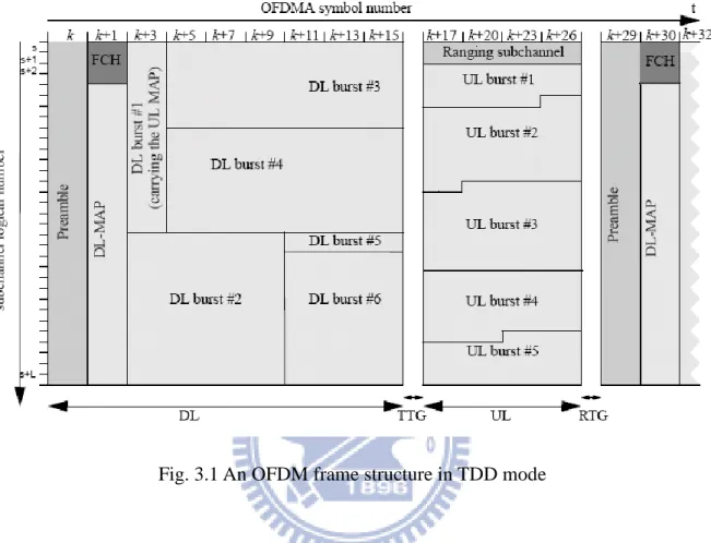
In the licensed band, IEEE802.16e system can support time-division duplexing (TDD) or frequency division duplexing (FDD). The other license-exempt bands, only TDD should be used. Fig. 3.1 shows a frequently referred model of TDD mode frame structure. The frame structure includes the following elements. The first transmitted symbol of a frame is the preamble symbol which its elements are known at the receiver. Preamble is used for cell search, synchronization, and channel estimation. Following the preamble, the frame control header (FCH) with fixed size is transmitted for resource allocation such as subcarrier used, length of DL-MAP and DL_Frame_prefix, The quadrature phase shift keying (QPSK) modulation with code rate 1/2 and four repetitions is used for FCH transmission. DL_MAP and UL_MAP following FCH message for resource allocation of the various users in DL and UL data bursts. Transmit transition gap (TTG) is used to give base station (BS) and subscriber station (SS)
18
enough time to change from down link mode to up link mode.
Fig. 3.1 An OFDM frame structure in TDD mode
For supporting various physical channel conditions, IEEE 802.16e defines two modes of sub-channel building method: the distributed subcarrier permutation mode, including partial usage of sub-channels (PUSC) and full usage of sub-channels (FUSC) types, and the adjacent subcarrier permutation mode, including adaptive modulation and coding (AMC) type.
In this thesis, PUSC mode is mainly supported and more details of the subcarrier allocation scheme were described in Section 3.3 of [3].
3.1.2 Preamble Format
The preamble symbol consists of a specific pattern known to the receiver and occupies the duration of an OFDM symbol time. It is used for frame detection, synchronization and initial channel estimation. IEEE 802.16e standard provides three types of carrier set for different
19
segments in preamble symbol which can be expressed as
PreambleCarrierSets s 3 k (3.1)
where s
0,1, 2
is the index of the subcarrier set, and kdenotes a running subcarrier index.These subcarriers in the preamble symbol are modulated by binary phase shift keying (BPSK) with a specific Pseudo-Noise (PN) code. The PN series modulating the pilots in preamble can be found in [1]. Each segment in a zone uses one type of preamble carrier set. For different FFT size, there are total 114 PN series to be chosen by the ID cell parameter and the segment index. The guard band subcarriers are contained both on the left and right side of the spectrum. The DC subcarrier is always be zeroed even if the type of carry set is 0. The power of the preamble subcarrier is boosted by a factor, 2 2 , to increase the reliability of preamble. The pilot
subcarrier pkin the preamble symbol are modulated as
1
Re 4 2 , Im 0 2 k k k p w p (3.2)where wk denotes the PN series, and Re
and Im
stands for the real and imaginary partof
.3.1.3 Pilot Modulation
The OFDM symbol structure is constructed using pilots, data, and null subcarriers. The symbol is first divided into basic clusters and null carriers are allocated. In down link PUSC mode, pilots and data carriers are allocated within each cluster as shown in Fig. 3.2. For the proposed system with two transmit antennas, when the pilot subcarrier is transmitted from one antenna, the other antenna will not transmit a pilot in the same subcarrier to avoid inter-antenna interference. The pilot location schemes periodically change every four OFDM symbols.
20 Symbol 4k+3 Symbol 4k+2 Symbol 4k+1 Symbol 4k Data subcarrier
Pilot subcarrier from antenna 0 Pilot subcarrier from antenna 1
Subcarrier Time
Fig.3.2 Pilot cluster structure
Each pilot is boosted 2.5dB over the average non-boosted power of each data subcarriers.
The value of the pilot modulation on subcarrier kshall be derived from a pseudo-random
sequence z . The pilot subcarriers k pk are modulated as
8 1
Re , Im 0 3 2 k k k p z p (3.3)3.1.4 Differences Between 802.16e and 802.16m
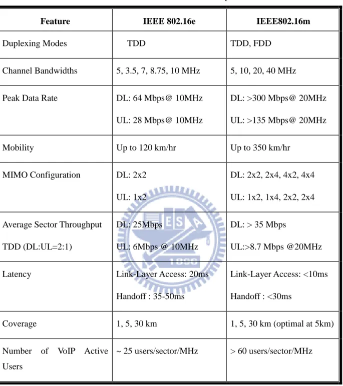
IEEE 802.16m [2] provides continuity to the first released of Mobile WiMAX (802.16e) and offer evolution path to existing WiMAX operators and win new operators targeting the deployments from 2012. It improves system performance, enables more flexible radio network architecture, and is fully backward compatible with 802.16e. The main differences between 802.16m and 802.16e are summarized in Table 3.1.
21
Table 3.1 802.16e and 802.16m comparison
Feature IEEE 802.16e IEEE802.16m
Duplexing Modes TDD TDD, FDD
Channel Bandwidths 5, 3.5, 7, 8.75, 10 MHz 5, 10, 20, 40 MHz
Peak Data Rate DL: 64 Mbps@ 10MHz
UL: 28 Mbps@ 10MHz DL: >300 Mbps@ 20MHz UL: >135 Mbps@ 20MHz Mobility Up to 120 km/hr Up to 350 km/hr MIMO Configuration DL: 2x2 UL: 1x2 DL: 2x2, 2x4, 4x2, 4x4 UL: 1x2, 1x4, 2x2, 2x4
Average Sector Throughput TDD (DL:UL=2:1)
DL: 25Mbps
UL: 6Mbps @ 10MHz
DL: > 35 Mbps
UL:>8.7 Mbps @20MHz
Latency Link-Layer Access: 20ms
Handoff : 35-50ms
Link-Layer Access: <10ms Handoff : <30ms
Coverage 1, 5, 30 km 1, 5, 30 km (optimal at 5km)
Number of VoIP Active Users
~ 25 users/sector/MHz > 60 users/sector/MHz
3.1.5 Major Parameters and Design Targets
The IEEE 802.16e specification for multi antenna technique is adopted in the proposed STBC-OFDM system, and the major parameters are summarized in Table 3.2.
22
Table 3.2 Major parameters of proposed STBC-OFDM system
Parameters Deriving formulas Values
FFT size (N) 1024
Symbol Length (Ns) 1152
Cyclic Prefix Length (Ng) 128
System channel bandwidth (BW) 10 MHz
Sampling frequency (Fs) 11.2 MHz
Subcarrier spacing (Δf) Fs/ N 10.94 kHz
Useful symbol time (Tb) 1/Δf 91.4 us
Guard time (Tg) (Ng /Ns)Tb 11.4 us
OFDMA symbol duration (Ts) Tb+Tg 102.8 us
Frame duration (TF) 5 ms
PUSC Number of null subcarriers (Nn) 184
Number of clusters (Nu) (NFFT-Nn)/14 60
Number of pilot subcarriers (Np) Nu2 120
Number of data subcarriers (Nd) Nu12 720
Design Target
Modulation Mode 16QAM
Uncoded Data Rate 27.32 Mbps
Vehicle Speed Up to 360 km/h
Normalized Maximum Doppler Frequency ( fd f ) 0.075
23
The system occupies a bandwidth of 10 MHz and operates in 2.5GHz frequency band. The sampling frequency is 11.2 MHz. FFT size (N) is set to 1024. Each OFDM symbol is composed of 1024 subcarriers, among which 720 and 120 subcarriers are data and pilots. The remaining 184 subcarriers are used either as a DC subcarrier or virtual subcarriers. In 802.16e, the modulation scheme of QPSK, 16QAM, and 64-QAM are supported for data subcarriers, while only QPSK is adopted for pilot subcarriers and preamble symbol. The length of cyclic prefix
(CP) is 128 sampling periods, equivalent to 1/8 of the useful symbol interval (Tb).
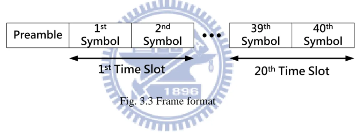
Fig. 3.3 depicts the frame format which starts with one preamble and is followed by 40 successive OFDM data symbols. A time slot is equivalent to the time duration of two OFDM symbols.
Preamble Symbol1st Symbol2nd Symbol39th Symbol40th
1st Time Slot 20th Time Slot
Fig. 3.3 Frame format
Originally, the proposed STBC-OFDM system and channel estimator design [3] is optimized for vehicle speed 120 km/h. In this thesis, we propose an STBC interference canceller to improve system performance and enable vehicle speed up to 360 km/h. The
coherence time at this speed is Tc 0.423 fd 0.75 ms, which is about 7.4 times of an OFDM
symbol period and is smaller than one frame. Theoretically, the channel should be treated as quasi-static. Under the assumption that the channel variation inside one time slot is insignificant, one should intuitively think of ICI as the major interference noise that hampers the accuracy of STBC decoding.
However, it has been shown that even if ICI is perfectly cancelled and the coherence time is as long as 13.3 times of an OFDM symbol, the system performance would be severely corrupted by CCI noise alone [6]. Furthermore, it has been demonstrated that CCI power is
24
larger than ICI power about 7~8 dB regardless of the channel variation rate [7]. Therefore, with the aid of proposed STBC interference canceller, a significant improve of system performance can be expected, and the design targets are listed in the bottom rows of Table. 3.1.
3.2 Overview of DFT-based Channel Tracking
Estimation
STBC-OFDM exploits transmission diversity to provide system performance improvement. However, for STBC decoding and our proposed STBC interference canceller, accurate channel state information (CSI) is essential. It is very difficult to obtain in mobile wireless channels. Therefore, high quality channel estimator with acceptable hardware complexity would be an advantage for our proposed STBC interference canceller. An DFT-based two stage channel estimator has been proposed in [3] to serve our purpose, and we will introduce its principle and architecture in this section.
3.2.1 Two-Stage Channel Tracking Estimation Method
Various DFT-based channel estimation method has been studied using either minimum mean square error (MMSE) criterion or maximum likelihood (ML) criterion have been studied for OFDM system with preambles [10, 11]. Since CSI and signal to noise ratio (SNR) are unavailable at receiver in real implementation, the ML scheme is easier to implement than MMSE scheme. Moreover, the decision-feedback (DF) scheme can be adopted in DFT-based channel estimation to use decision data as pilot to track channel variations for providing sufficient tracking information. Recently, Ku and Huang [12] presented a two-stage DF DFT-based method to apply in STBC-OFDM systems under fast time-varying multipath channels. They concluded that a refined two-stage channel estimator is more robust than classical DFT-based method.
An initialization stage uses a multipath interference cancellation (MPIC)-based decorrelation method to identify the significant paths of channel impulse response (CIR) in the beginning of each frame. However, the CIR estimated by the preamble cannot be directly applied in the following data bursts since the channel is time-variant. Thus a tracking stage is
25
then used to track the path gains with known CIR positions. The details are described as follows.
(A) Initialization Stage
First, two parameters NPandW are defined as a presumptive path number of a channel B
and an observation window set, respectively. Second, the cyclic cross-correlation CRP
between the received and transmit preambles as well as the normalized cyclic auto-correlation
PPC of the transmitted preambles are calculated. The index l and which stand for a path
computing variable and the number of legal paths found by the MPIC-based decorrelation are
initialized to zero. Third, the process is found by picking only path whose time delay l yields
the largest value in CRP
, for lWB. If the path delay l is larger than the length of CP, this path is treated as an illegal path and discarded by settingCRP
l 0. Otherwise, this path isrecorded as the -th legal path with a time delay l and a averaged complex path gain
RPl C l
. Note that l is an estimation of the actual averaged complex path gain hl in
(2.11).
Then, the interference associated with this legal path is canceled from CRP
to obtain arefined cross-correlation function
RP RP PP , B\ 0, , l 1
C C C W (3.4)
Meanwhile, is increased by one. The value of l is also increased by one at the end of each
iteration, and the iterative process is continued until l reaches the presumed value of NP.
(B) Tracking Stage
26
multipath delays l( )i , the averaged multipath complex gains l( )i , for
( )
0, , i 1
l , and
the corresponding CFRs, where i is corresponding to the i -th transmit antenna. Under the
assumption that the multipath delays do not change over the duration of a frame, the DF
DFT-based channel estimation method in ts-th time slot can be equivalently expressed in
Newton’s method as [13]
, ,
, , -1 2 2 * * , , , , 1, 1 M 2, H F S ts ts ts ts S F F S X X R k k k R k X X X X (3.5)
( ) (i) ( ) ( ) , IDFT , 2 ( ) DFT q F F [ , ] ; 0,1, , 1 , 0,1, , 1 i l i i ts ts m j i m l e N m N l L (3.6) -1 ( ) ( ) ( ) ( ) (i) , , 1 DFT , Mtsi=Mtsi Fi Ei qts (3.7)The vector ts,
k
ts( )i,
k :i1, 2
calculates the difference between the previous estimated CFR vector Mts,1
Mts( )i,1:i1, 2
and the least-square (LS) estimated CFR of the ts-th time slot, where the subscript stands for the iteration index. The inverse DFT (IDFT) matrix FDFT( )i multiplying by ts( )i, in (3.6) is to form the gradient vector q(i)ts, inNewton’s method. In addition, the weighting matrix ( ) -1
Ei
in (3.7) is in fact the inverse of the
Hessian matrix in Newton’s method. The
l l -th entry of , ' ( )Ei is given by
( ) ( )'
( ) ( )'
( ) 2 2 E , ' cos sin i i i i l l l l i k k k k l l j N N
(3.8)where Θis a subset of data subcarrier indices.
In this channel estimation method, pilot symbols as well as data symbols are simultaneously adopted to perform tracking iterations. From the view point of optimization, since pilots inserted in each OFDM symbol are more reliable than the decided data symbols,
27
they should play a dominant role in providing a global direction search at the first tracking iteration. Thus, the first iteration of the channel tracking is modified as
( ) ( ) ( ) ( )
,1 ,0 DFT ,
M =Mtsi tsi Fi qtsi
(3.9)
where the gradient vector (i)
q is calculated according to (3.5)-(3.6) by using the pilot
subcarrier set J instead of the set Θ, and the value is an experimental constant of step
size to provide the best performance.
3.2.2 Channel Estimator Architecture
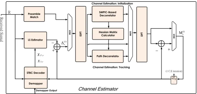
Based on the two stage DFT based algorithm studied in [12], an low complexity and accurate implementation was proposed by [3]. The overall block diagram of this proposed channel estimator is shown in Fig.3.4. The initialization stage is decomposed to a preamble match, an IFFT, a straight MPIC (SMPIC)-based decorrelator, and an FFT. The tracking stage is decomposed to a STBC decoder, a demapper, an LS estimator, an IFFT, a path decorrelator, a Hessian matrix calculator, and an IFFT. Moreover, the IFFT and FFT are shared between the initialization stage and the tracking stage.
28
M
U
X
Channel Estimation: Initialization
Channel Estimation: Tracking
Demapper Output Channel Estimator
Path Decorrelator Preamble Match LS Estimator STBC Decoder Demapper M U X M U X SMPIC-Based Decorrelator Hessian Matrix Calculator ID FT D FT Reg . (1 C.E iteration) R ec eiv ed S ig na l
Final Decision Output
(i) M R ( )i , F X , S X
29
3.3 Co-carrier Interference modeling
CCI noise component in STBC-OFDM system was defined by (2.20). It results from channel variation between two symbol intervals inside one time slot. Various studies has demonstrated that CCI is the major impact on STBC-OFDM system [6-9], so CCI problem shall be solved first than ICI problem in our proposed algorithm.
To calculate CCI noise, we need to know the frequency domain channel matrix of two OFDM symbol intervals between two transmit antennas and receive antenna, i.e.,
( ) ,
H [ , ], ts bi k k b 1, 2 ,i 1, 2 ,k 0,1, ,N1 . Nevertheless, most channel estimator design for STBC-OFDM system are aimed at estimating the averaged CFR over two symbol intervals inside one time slot, not the CFR of each symbol interval. The goal of this thesis is to provide an efficient solution for any existing STBC-OFDM systems suffering interference, so we propose an algorithm using only the existing time slot CFR estimation results to approximate the CFR of the two symbol intervals inside the time slot.
Fig.3.5 Relationship between CFR estimations in time domain
Fig.3.5 demonstrates the relationship between CFR tracking estimations in time domain, where Mts v, denotes the estimated CFR of the -th tracking iteration in current time slot,
30
1
Mts denotes the final CFR estimation of previous time slot, and Dts, Mts1Mts v, .
,1
Uts [ , ]k k , Uts,2[ , ]k k represents our approximated CFR of the 1st and 2nd symbol interval
respectively, and k
0,1, ,N1
. We should note that no matter what method is used toobtain Uts,1[ , ]k k and Uts,2[ , ]k k , the following constraint shall hold
,1 ,2
,1
U [ , ] U [ , ]
2 ts k k ts k k Mts v (3.10)
A low cost solution for Uts,1[ , ]k k is to interpolate the already existed information, Mts v, and 1
Mts . But the estimation of CFR in the 2
nd
symbol interval, Uts,2[ , ]k k , is not-causal for real implementation, a predictive approach is needed.
In the study of [14], three types of predictive model are proposed for time varying channel using only previous information from estimator. First one, the zeroth order predictive model assume the variation between Uts,2[ , ]k k and Mts v, can be ignored, and simply set them equal,
, ,2
Uts [ , ]k k Mts v
. The second one is the 1st order predictive model; it assumes the variation of CFRs separated by the same time interval are the same. In other word, Uts,2[ , ]k k is linearly
extrapolated from Mts v, and Mts1 . The last one is the 2rd order predictive model; it
extrapolates Uts,2[ , ]k k using 2nd order fitting, and requires the CFR estimation of the
previous two time slots. They concluded that the 1st order predictive model outperforms the other two under time varying channel. Moreover, only by applying the 1st order predictive model on Uts,2[ , ]k k , we can interpolate Uts,1[ , ]k k independently without violating the
constraint in (3.10). As a result, our proposed approximation is given by
, 1 , 1 ,1 ,2 3 1 U [ , ] , (linear interpolation) 4 4 5 1 U [ , ] ,(linear extrapolation) 4 4 M M M M ts v ts ts v ts ts ts k k k k (3.11)
31
3.4 Inter-carrier Interference modeling
In time variant channel, both CCI and ICI appears in STBC-OFDM systems, and CCI component has been proved to be more significant than ICI component. As a result, proposed schemes for STBC interference cancellation target only on CCI and simply ignore ICI problem[6-9]. In this section, we will propose a low complexity algorithm to model ICI by exploiting the information used for CCI modeling in section 3.3. In this way, CCI and ICI noise
can be cancelled simultaneously with little overhead. The variant ICI noise tsis comparably
smaller than βts, and it’s very difficult to obtain an accurate estimation from existing time slot
CFR. So we ignore this component and focus on modeling the averaged ICI noise.
3.4.1 Polynomial Modeling of Channel Variation
The averaged frequency domain matrix H( )tsi is defined in (2.11) and (2.18). It requires
temporal variation complex gain inside each useful symbol interval but the channel estimator provides only the temporal averaged CSI. As a result, we adopt a LS fitted polynomial method
[15-20] to model the detail of the l-th complex path gains between the i -th transmit antennas
and receive antenna, as follows:
1 ( ) 0 [ , ] [ ] c N i i d l l d q l d q q
ε (3.12)where l i
q is the modeled complex path gain at time sample q ,( )
[ , ]
i
l d
is the d -th
order complex polynomial coefficient, d
0,1, ,Nc1
, and(Nc1) denotes the order ofthe LS fitting polynomial. It requires N observations to solve this c (Nc1)-th order LS fitting
problem, so we consider the estimated CFR of the latest N time slots and group them as a c
observation block for each ICI modeling computation. As illustrated in Fig.3.6, every time
slot inside an observation block is distinguished by an index, n , where nNc1stands for the