行政院國家科學委員會/經濟部能源局
「能源科技學術合作研究計畫」成果報告
無線感測網路應用於能源節約之個人化適性服務
計畫類別:
█
個別型計畫 □ 整合型計畫
計畫編號:NSC 96-2623-7-009-002-ET
執行期間:96 年 1 月 1 日至 96 年 12 月 31 日
計畫主持人:曾煜棋
計畫參與人員:
潘孟鉉、葉倫武、梁家銘、吳鈞豪、胡淑琼、陳志誠、盧奕丞
成果報告類型(依經費核定清單規定繳交):□ 精簡報告
█
完整報告
本成果報告包括以下應繳交之附件:
□赴國外出差或研習心得報告一份
□赴大陸地區出差或研習心得報告一份
□出席國際學術會議心得報告及發表之論文各一份
□國際合作研究計畫國外研究報告書一份
處理方式:除產學合作研究計畫、提升產業技術及人才培育研究
計畫、列管計畫及下列情形者外,得立即公開查詢
□涉及專利或其他智慧財產權,
□一年□二年後可公開查詢
執行單位:國立交通大學資訊工程系
中 華 民 國 96 年 12 月 17 日
摘要
無線感測器網路提供了一種非常方便的形式來監控環境中之資
訊,故在近幾年來,無線感測網路已被大量運用在各項應用方面。本
計畫使用無線感測器網路來監控室內之環境資訊,並結合控制系統至
室內家電,來達到省電之效益。
本系統以節約能源為目標,並且考量到不同使用者均有不同偏
好,且在從事不同行為時,所需之環境因素也不儘相同,且根據使用
者事前設定好之偏好值,並加上無線感測器所收集之即時環境資訊,
再透過一套可適性之決策演算法,計算出最適於目前環境之設定值,
且透過幾項家電控制協定,來將室內之電器自動的調整至最適於使用
者之狀態,以滿足所有使用者之偏好值。
關鍵字:節能、無所不在的運算、智慧型生活環境、無線通訊、無線
感測網路
Abstract
Wireless sensor networks (WSNs) provide a convenient way to
monitor the physical environment. In recent years, WSNs have been
widely discussed in many applications. We combine wireless sensor
networks and control systems to achieve energy saving.
Different users have different preference. When user does different
activities, he needs different environmental factors. The goal of our system
is energy saving. According the environmental information which is
collected by wireless sensor networks, our system would do an adaptive
decision algorithm. According the result of decision algorithm, our system
would adjust the appliance automatically to achieve energy saving.
Keywords:energy conservation, pervasive computing, smart environment,
wireless communication, wireless sensor network
一、 前言
電力的發現是人類史上非常重要的里程碑,它不但推動了後續許
多的發明,更豐富了我們的生活,直到今日,我們的生活沒有一天不
能不使用到電力。雖然電力便利了我們的生活,但近幾年來,電力的
過渡使用,造成了電力的供不應求,舉例來說,在炎炎夏日裡,電力
往往因大家過度的使用,常超過了可負荷的極限,而發生了跳電的情
形,過度用電不但容易造成用電緊張,更可能為了製造這些電力而造
成環境的汙染。因此,為了響應日趨重視的環境意識,
『節約用電』可
說是非常重要的議題。
二、 研究目的
在日常生活之中,電力消耗最多的莫過於暖氣機(Heating)、通風
設備(Ventilating)與冷氣機(Air Conditioning),除此之外,還有電燈也
佔了不少耗電之比重,這些電器統稱為 HVAC 系統,根據資料顯示,
HVAC 系統消耗了三分之一以上之用電量,倘若能夠節省這些電器之
耗電量,勢必可以節省十分可觀之能源。
根據統計資料顯示,最常見之電源浪費情形,為使用者之疏忽,
舉例來說,在一辦公室內,當人員離開時,常常忘了關閉其座位之檯
燈,仰或是當辦公室人員全離去時,忘了關閉辦公室內的冷氣,此類
的疏忽,所消耗之能源,一年累績下來,所以浪費之電力相當可觀,
倘若能夠有一套良好的機制,能夠節省此類的能源,不儘能為地球之
環保儘一份心力,也能夠節省公司電力之開銷。
除了使用者之疏忽以外,在室內之中,冷氣之溫度之高低與日光
燈之強弱,也是影響用電量很重要的一環,舉例來說,室內人員偏好
之空調溫度並非非常低時,空調可不必開太冷,也可搭配電扇來使用,
冷氣調高一度可節省之能源即相當可觀了,除了溫度之外,每位人員
偏好光線強度也不儘相同,所提供之光度越高,所花費之電量亦越高,
若能將室內之光線開啟在適當之光度之下,且能夠滿足所有使用者之
偏好光度,也可節省不少用電。
為了達到上述的研究目的,我們使用無線感測器網路,利用無線
感測器之特性,來收集環境中之資訊,並整合至室內之家電之中,來
達到家電可調適性之自動化,並在符合每位使用者需求之下,做一項
能源最有效之運用。
三、 文獻探討
近幾年來,無線感測網路被廣泛的運用在各項領域之上,最貼近
於人們日常生活之應用,莫過於應用於一般家電之上,主要為省電與
滿足使用者偏好為主要之議題。如何根據使用者在室內之行為與位
置,來決定家電之反應,國內外已有不少此類之相關研究,舉例來說,
在[1]之中,作者提出了一套系統,藉由情境感知來建構出智慧型之生
活環境,其主要是利用感測器來感測環境之資訊,來做為家電控制之
依據,以達到情境感知之目標。而有些研究,則是著重在分析使用者
之歷史記錄,在[2]之中,其記錄使用者多筆歷史記錄,藉由這些歷史
記錄,可推測使用者未來之行為與位置等等,讓此環境能夠自動化的
來因應使用者之需求。而有些則是提出了一套軟體架構,在[3]之中,
其提出了一套一般性之軟體架構,來達到家電控制的功能。
上述的種種研究,主要為家電控制與家電自動化,而有些研究,
則是集中在單一家電之上,舉例來說,在[4][5][6][7]裡,主要探討的
均為燈光之控制,如何調節室內之燈源,以滿足使用者需求,仰或是
能達到省電之功能,在[5]之中,其定義了多種不同之使用者需求與其
相關之代價函數,而其目標主要為最小化此代價函數,來滿足使用之
需求。而在[6]之中,則是將燈光控制問題描述為一能源消耗與滿足使
用者偏好光度之損益問題,其對每一位使用者偏好之光度值,均個別
定義一項效益函數,而其目標為最大化所有使用者之效益函數,讓多
數使用者均能夠有其偏好之光度值。而[4]和[7]則是著重在省電之議題
之上,利用無線感測網路之優勢,來節省大樓內之各項能源消耗。
四、 研究方法
本系統以省電為目標,來自動的關閉室內不必要開啟之電器,並
能夠滿使用者之偏好,而在滿足使用者偏好方面,主要是集中在光度,
來做為實驗與實做之項目,但本系統為一套一般性之系統,可直接套
用於其他同性質之環境因素,如溫度、聲音等等,讓使用者能夠滿足
其生活空間之的各項環境因素。
1、 系統情境
在環境中的使用者,其身上會備帶有一識別裝置,此裝置會發送
無線訊號,讓本系統可得知此使用者之位置,以其辨別使用者身份,
且使用者可透過此裝置,讓本系統得知其目前所從事之行為,根據不
同行為,本系統可自動的來調節其需之電器,及其所需之光源強弱,
用以節省能源。圖一為系統情境示意圖,室內有冷氣、檯燈以及天花
板之日光燈,而本系統會根據使用者之行為,來自動之開啟或關閉電
情境示意圖,不同之行為,所需之光度均不相同,舉例來說,看電視
儘需適當之亮度,但看書時,則需要較強之光度,讓使用者能夠在其
作業面上專心閱讀,而本系統會依據感測器數值以及使用者行為與喜
好,來自動調整光源強弱,用以節省能源。
圖一:系統情境示意圖
看電視,儘需 適當的亮度。 看書,需較 亮的光度。圖二:光度偏好情境示意圖
2、 光度特性
為了滿足每位使用者偏好的光度值,首先要了解不同光度在不同
距離下所呈現之關系,以及不同光度,所消耗之能源為多少,故我們
做了底下幾項實驗,以輔助本系統模型之設計與實作。
第一項實驗為距離與亮度之實驗,此實驗使用一盞燈源,並每次
固定其亮度,但在不同距離之下(0、5、10、15 和 20cm)測量其光度值
(lux),並做多次實驗,每次調整不同之光度值,其結果為圖三(a)所示,
在開啟同樣光度之條件之下,距離越遠,則感測到之光度越低,若以
光源距離為 0 cm 為基準值(在此訂為 1),而其他距離依此做標準化,
則可得到圖三(b),由圖中發現,所有亮度值之實測結果,都重合於同
一線段上,由此可得知,若系統事先量測每定點每盞光源所以提供之
最強光度,則之後可由此關系來推得該光源所開啟之強度。
圖三:亮度衰減實驗
第二項實驗為亮度與耗電之實驗,此實驗為開啟一盞檯燈,固定
電壓為 12V,每次將檯燈之光度增加 100 Lux,並記錄其電流值(mA),
和其對應之耗電功率,而由圖四可得知,光度越強,則耗電功率越大,
故若能控制適當的亮度,則勢必能節省可觀之耗電量。
光度耗電實驗 0 1000 2000 3000 4000 5000 6000 7000 500 600 700 800 900 1000 1100 1200 1300 1400 1500 光度(Lux) 耗電量 電流(mA) 功率(mW)
圖四:光度耗電之實驗
3、 系統模型
本系統是應用於室內之電器,舉例來說,如冷氣,其所影響之範
圍為整間房間,故系統模型並不定義其有效範圍,但如光度,如圖三
之實驗結果所示,其影響範圍與距離有密切之關系,故本系統將環境
切割為多個格網,且定義每盞光源可影響之格網。
圖五:網路情境示意圖
在本系統中,一般照明設備之照明可能會影響多個網格區域,例
如圖五之光源 4 會影響網格五與格網六內之固定型感測器所感測之數
值。由於光線也是隨著距離而衰減,因此我們假設在系統建置階段我
們可以得知一般照明設備對網格內感測器亮度值之影響程度。例如:
某一般照明設備 A 對網格 G
j的亮度影響程度為 0.7,則代表在網格 G
j中感測器所感測之亮度值為一般照明設備所發出之亮度值的 0.7 倍。
根據圖三顯示之亮度衰減實驗,由這實驗可知,無論燈光目前之調控
值為何,光線衰減程度都可為一線性關係。在本系統中,我們將一般
照明裝置對網格之影響程度記錄於一矩陣 W 中。我們可以利用 W 矩
陣來求得目前一般照明設備所提供之亮度值,其計算方法如下:假設
我們已知每個一般照明裝置所處之位置,我們利用所處位置之資訊由
取出 m 條相對應之 row,建構一矩陣 W
',並取出一般照明裝置所處
位置之感測器亮度值記錄於一列矩陣 S
f,假定一般照明設備目前提供
之亮度值為 L
D,則 S
f、W
'及 L
D有這下列關係:S
f=W
'L
D。L
D可使用
一簡單地以解聯立方程式求得。
4、 系統架構
本系統主要可分為三大部分,無線感測網路、控制伺服器以及執
行機構。底下分述各項之細節。
E th erne t RS232Portable sensors Fixed
sensors
Sensor data handler User status handler Decision handler Dimmer handler Illumination requirement database
Administrative user interface Control Server
Report forwarding Commands
On-level settings
Trigger
Light intensity report User status update
WSN Actuators
Sink node
Device control algorithm Adaptive illumination decision algorithm INSTEON Lighting devices UPnP Query
圖七:系統實作堆疊圖
z 無線感測網路
此部分我們使用了 Jennic[8]做為無線傳輸之節點,Jennic 為符
合 IEEE 802.15.4[9]協定之無線感測模組,其運作在 2.4 GHz 頻帶
之上,而在感測器之部分,我們自製了一塊感測板,其使用 Si
photodiode[10]做為光度感測器,並在此感測板上設置數個按鈕,
使用者可回報其目前之行為至本系統,而使用者則隨身攜帶此感
測器,用以感測其作業面之照度,並可回報其行為。而在環境之
中,我們佈建了許多無線感測器,這些感測器會定期回報環境中
的資訊,如光度、温度等等,並且藉由這些感測器之訊號強弱,
本系統可定位出使用者目前所在之位置。環境中之無線感測器均
將資料回傳到無線基地台(sink),而此無線基地台以 RS232 連接至
控制伺服器。
z 控制伺服器
此部分為系統之核心所在,主要採用 Java 程式語言來撰寫,
可分為五大部分,即 user status handler、decision handler、sensor data
handler、dimmer handler 以及 administrative user interface,底下分
述各部分之細節。
i.
Sensor data hander:此部分會定期的接收無線感測器網路
所傳回之環境資訊,如光度、溫度等,以及使用者所回傳
目前從事之行為。
ii.
User status handler:根據 sensor data handler 所回傳之資
訊,可計算出使用者目前所之位置,並予以記錄,當使用
者位置或其行為有改變時,則通知 decision handler,以重
新計算出最適於目前狀況之節能策略。
iii.
Decision handler:此部分接收了由 sensor data handler 傳回
之環境資訊,以及 user status handler 所維護之使用者資
訊,再加上使用者事前定義好之環境偏好,如偏好之溫度
或亮度等,綜合以上資訊來執行一項可適性調節演算法,
來決定出目前環境中之電器應如何開啟或調整,並將此決
策傳送至 dimmer handler。
iv.
Dimmer handler:此部分會根據 decision handler 所計算出
之結果,發送一對應之指令至室內之電器,在目前實作之
版本中,有 INSTEON 協定與 UPnP 協定。
v.
Administrative user interface:除了底層複雜的系統之外,
我們還實作了一套完整的介面,讓管理者可以透過此介面
來維護和監控整套系統,舉例來說,可藉由此介面來設定
使用者偏好之光度值,或藉由此介面來觀看系統中所有感
測器之讀數與狀態等。
z 執行機構
在目前我們實作的項目裡,執行機構分成兩部分,一般電器和
局部照明設備使用 INSTEON[11]來做為控制之協定,我們使用
INSTEON PowerLinc 控制器和 INSTEON LampLinc 調光器來控制
檯燈,其中 INSTEON PowerLinc 以 RS232 連接至控制伺服器,而
控制伺服器從 RS232 發送 INSTEON 指令至 INSTEON PowerLinc
後,此指令透過電力線傳送至 INSTEON LampLinc,而 INSTEON
LampLinc 則根據指令內容,來關閉、開啟或調整電流大小,以控
制相對應之電器。
而在全區照明設備方面,則是使用 UPnP[12]來做為控制之協
定,我們實作了 UPnP Lighting Controls v1.0 之標準來控制室內之
全區照明設備,控制伺服器發送 UPnP 指令至 UPnP 控制伺服器,
而此 UPnP 控制伺服器則連接至 EDX-F04[13]調光器,此調光器可
根據指令來調整全區照明之強弱,其調控刻度為 0 至 100。
五、 結果與討論
在本節模擬之中,以一小型辨公室為情境,並假設有五位使用者、
一台冷氣機與五盞檯燈,其中每盞檯燈均位於每位使用者之辨公桌
上,表格一表示了不同電器所耗費之能源,而對於冷氣機,在此假設
每降攝氏一度,則需要多增加 100 瓦特的用電。
表格一:電器耗電量
電器
耗電量
冷氣 800
瓦特/小時 (28°C)
檯燈 80
瓦特/小時
表格二:使用者偏好溫度
使用者
偏好溫度值
A
25°C
B
27°C
C
26°C
D
22°C
E
24°C
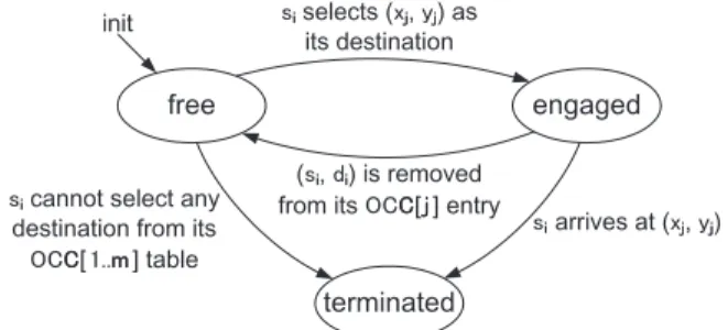
對於辨公室內使用者之行為,我們以二狀態離散馬可夫模型
(two-state discrete Markov)來模擬其每小時之行為,如圖八(a)所示。每
位使用者有兩種狀態 leave 或 stay,當使用者狀態為 leave 時,其檯燈
之狀態為關閉。而當使用者狀態為 stay 時,我們以另一個二狀態馬可
夫模型來描述其每二十分鐘之行為,如圖八(b)所示,其狀態可為 still
stay 或是 temporarily leave,當使用者之狀態為 temporarily leave 時,
若不使用本系統,則其辨公桌上之檯燈為開啟,若使用本系統則為關
閉。對於每位使用者,其均有不同之偏好溫度,如表格二所示,當室
內有兩位以上之使用者,則冷氣開啟之溫度為使用者偏好溫度之平均
值,當不使用本系統時,冷氣只有在使用者進入辨公室才會更動,當
有使用者離開時並不會調整冷氣溫度。
圖八:使用者之二狀態離散馬可夫模型
圖九為十小時內之能源消耗,從圖九可觀察到,當不使用本系統
時能源消耗均大於使用本系統,因為當使用者暫時離開辨公桌時,其
檯燈之狀態仍然為開啟,而若是使用本系統,則本系統會自動偵測到
無人在該辨公桌,則自動關閉該盞檯燈,用以節省不必要之能源浪費。
圖十為不同人數之總能源消耗,由圖中可觀察到,使用本系統可節省
約 16.5%~46.9%之能源。
圖九:十小時內之能源消耗
圖十:不同人數之總能源消耗
本系統將無線感測網路結合於一般日常生活中,以節約能源為目
標,並且考量到環境中使用者之行為與其偏好,如光度、溫度等,在
滿足室內使用者之需求之下,來達到省電的需求。並以模擬來驗證使
用本系統確實可節省大量電源,且實做出系統之雛型。
六、 計畫成果自評
z 熟悉並了解無線感測傳輸節點(Jennic)的各項功能,並可將收到的
資訊加以處理,且回報至控制伺服器。
z 使用 Si photodiode 做為光度感測器,並實際設計出此電路板,且
將感測到之資料傳送至無線感測傳輸節點。
z 設計一套無線通訊協定,來將無線感測器節點所偵測到的環境資
料傳回至 sink,並回報至控制伺服器。
z 設計了一套省電之演算法,可根據使用者之行為,及其位置,來
決策出目前室內應開啟那些電器,及其強弱。
z 實作出 UPnP 燈光控制標準,用以整合至本系統,來控制全區照
明設備。
z 結合 INSTEON 協定,用以控制一般家電其局部照明設備。
z 撰寫模擬,用以驗證所設計之演算法確實可節省非常可觀之用電
量。
z 整合上述所有元件,並將其整套系統完整實作。
研究成果
[1]
L.-W. Yeh, Y.-C. Wang, and Y.-C. Tseng, “iPower: An Energy
Conservation System for Intelligent Buildings by Wireless Sensor
Networks", Int'l J. of Sensor Networks, to appear
[2]
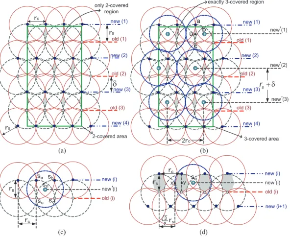
Y.-C. Wang and Y.-C. Tseng, "Distributed Deployment Schemes for
Mobile Wireless Sensor Networks to Ensure Multi-level Coverage",
IEEE Trans. on Parallel and Distributed Systems, to appear (SCI, EI).
參考文獻
[1] S. Helal,W. M. H. E. Zabadani, J. King, Y. Kaddoura, and E. Jansen, “The gator
tech smart house: a programmable pervasive space,” IEEE Computer, vol. 38, no. 3,
pp. 50–60, 2005.
[2] S. K. Das, D. J. Cook, A. Battacharya, E. O. H. III, and T. Y. Lin, “The role of
prediction algorithms in the mavhome smart home architecture,” IEEE Wireless
[3] H. Schulzrinne, X. Wu, S. Sidiroglou, and S. Berger, “Ubiquitous computing in
home networks,” IEEE Communications Magazine, vol. 41, no. 11, pp. 128–135,
2003.
[4] F. O’Reilly and J. Buckley. Use of wireless sensor networks for fluorescent
lighting control with daylight substitution. In Proc. of Workshop on Real-World
Wireless Sensor Networks (REANWSN), 2005.
[5] H. Park, M. B. Srivastava, and J. Burke. Design and implementation of a wireless
sensor network for intelligent light control. In Proc. of Int’l Symposium on
Information Processing in Sensor Networks (IPSN), 2007.
[6] V. Singhvi, A. Krause, C. Guestrin, J. H. Garrett, and H. S. Matthews. Intelligent
light control using sensor networks. In Proc. of ACM Int’l Conference on
Embedded Networked Sensor Systems (SenSys), 2005.
[7]
Y.-J.Wen, J. Granderson, and A. M. Agogino. Towards embedded
wireless-networked intelligent daylighting systems for commercial buildings. In
Proc. of IEEE Int’l Conference on Sensor Networks, Ubiquitous, and Trustworthy
Computing (SUTC), 2006.
[8] Jennic, JN5121 IEEE 802.15.4 Evaluation Kit. http://www.jennic.com/.
[9] IEEE standard for information technology - telecommunications and information
exchange between systems - local and metropolitan area networks specific
requirements part 15.4: wireless medium access control (MAC) and physical layer
(PHY) specifications for low-rate wireless personal area networks (LR-WPANs),
2003.
[10] S1133 si photodiode. http://cn.100y.com.tw/PNoInfo/10155.htm.
[11] INSTEON, Lamplinc and Powerlinc controller. http://www.insteon.net/.
[12] UPnP Forum. http://www.upnp.org/.
[13] EDX-F04. http://www.liteputer.com.cn/china/liteputer-tw/product.asp.
附件
z 附件一:L.-W. Yeh, Y.-C. Wang, and Y.-C. Tseng, “iPower: An Energy
Conservation System for Intelligent Buildings by Wireless Sensor Networks”,
Int'l J. of Sensor Networks, to appear
z 附件二:Y.-C. Wang and Y.-C. Tseng, "Distributed Deployment Schemes
for Mobile Wireless Sensor Networks to Ensure Multi-level Coverage",
IEEE Trans. on Parallel and Distributed Systems, to appear (SCI, EI).
附件一
L.-W. Yeh, Y.-C. Wang, and Y.-C. Tseng, “iPower: An Energy Conservation System
for Intelligent Buildings by Wireless Sensor Networks", Int'l J. of Sensor Networks,
to appear
iPower: An Energy
Conservation System for
Intelligent Buildings by
Wireless Sensor Networks
Lun-Wu Yeh
Department of Computer Science,
National Chiao-Tung University, Hsin-Chu, 30010, Taiwan E-mail: [email protected]
You-Chiun Wang
Department of Computer Science,
National Chiao-Tung University, Hsin-Chu, 30010, Taiwan E-mail: [email protected]
Yu-Chee Tseng*
Department of Computer Science,
National Chiao-Tung University, Hsin-Chu, 30010, Taiwan E-mail: [email protected]
*Corresponding author
Abstract: Wireless sensor networks (WSNs) provide a convenient way to monitor the physical environment. Exploiting the context-aware capability of WSN to achieve energy conservation in intelligent buildings is an attractive direction. We thus propose an iPower (intelligent and personalized energy-conservation system by wireless sensor networks) system which combines WSNs and appliance control devices to provide per-sonalized energy conservation services. A WSN is deployed in each room to monitor the usage of electric appliances and to help determine if there are electric appliances that can be turned off for energy conservation. The iPower system is quite intelligent and can adapt to personal need by automatically adjusting electric appliances to satisfy users’ requirements. The design and implementation details of iPower are reported in this paper.
Keywords: context awareness; energy conservation; sensor network; smart environ-ment; wireless communication.
Reference to this paper should be made as follows: Yeh, L.W., Wang, Y.C. and Tseng, Y.C. (2007) ‘iPower: An Energy Conservation System for Intelligent Buildings by Wireless Sensor Networks’, Int. J. Sensor Networks, Vol. 1, Nos. 1/2/3, pp.XX–XX. Biographical notes: Lun-Wu Yeh received his M.S. degrees in Computer and Information Science from the National Chiao-Tung University, Taiwan, in 2005. He is currently pursuing Ph.D. in Computer Science from the Chiao-Tung University, Taiwan. His research interest is wireless sensor network.
You-Chiun Wang received his Ph.D. in Computer Science from the National Chiao-Tung University, Taiwan, in 2006. He is currently a postdoctoral research associate at the Department of Computer Science, National Chiao-Tung University, Taiwan. His research interests include wireless communication, mobile computing, and sensor network.
Yu-Chee Tseng received his Ph.D. in Computer and Information Science from the Ohio State University in 1994. He was an Associate Professor at the Chung-Hua University (1994∼1996) and at the National Central University (1996∼1999), and a
1 Introduction
The discovery of electricity is one of the most important milestones in human history. Electricity is so essential in our daily life that many people cannot live without it. However, today, energy has been overly used and energy shortage has become a global concern. According to the re-port in Gassmann et al. (2001), more than one third of elec-tricity is spent on HVAC systems, which include heating, ventilating, air conditioning, lighting, and other related equipments. According to experiences, a large portion of energy consumed by HVAC systems is due to improper use of electric appliances. Therefore, how to exploit the text information of an environment to automatically con-trol the usage of electric appliances has a great potential to reduce the waste of energy.
In this work, we therefore propose an intelligent and personalized energy-conservation system by wireless sensor networks (iPower) to reduce energy consumption of HVAC systems by exploiting the context-aware capability of sen-sors. In the iPower system, WSNs are deployed in rooms of a building to collect information of the environment. Such information is reported to a control server to determine whether to turn off those unnecessary electric appliances in the building. Such a system needs to be designed with user friendliness in mind to minimize the involvement of users in making decisions. As an example, when sensor nodes detect a low temperature or a high brightness in a likely unoccupied room, they can report to the server that the electric appliances in that room (e.g., air conditioners or lights) could be turned off. The server then sends an alarm signal to notify people in the room that the electric appli-ances could be turned off shortly. If there are still users in that room, they can signal the system that these appli-ances should not be turned off by triggering some events (such as making some voices, changing the light reading of any sensor, or moving any furniture attached with sen-sors). If there is no such intentional events made by human being detected in a predefined amount of time, the server will turn off the electric appliances through some power-line control devices. In this way, the iPower system can work even if users are not wearing any particular badge.
In the iPower system, we also provide personalized ser-vices in which electric appliances can be automatically ad-justed to satisfy users’ preferences. In particular, each user can create a profile to describe his/her favorite tempera-ture and brightness. Such users are considered priority users and need to carry user identification devices so that our system can retrieve their profiles. When there are pri-ority users in a room, the server will adjust the air condi-tioners and lights in that room according to the profiles of these users.
The rest of this paper is organized as follows. Section 2 reviews some related works. Section 3 presents the design of our iPower system. Section 4 gives the implementation experiences. Section 5 gives some simulations to evaluate
our system. Section 6 concludes this paper and discusses some research issues in our system.
2 Related Works
WSN has been widely used to provide context informa-tion in smart spaces/environments. How to automatically control electric appliances according to users’ locations and their requirements has been intensively discussed for smart homes/offices. The work in Schulzrinne et al. (2003) con-siders a ubiquitous computing architecture in which elec-tric appliances are controlled by a SIP (session initiation protocol) (Rosenberg et al., 2002) server, under which ar-chitecture users can make calls to communicate with the SIP server to control their electric appliances. In the MavHome system (Das et al., 2002), the mobility pattern of a user in a house is exploited and is forwarded to the system to provide advanced services (e.g., controlling the corresponding electric appliances) in the predicted loca-tions of the user. In Semantic Space (Wang et al., 2004), the authors propose some semantics to describe the en-vironment, which can be used to query the status of the environment where users are located. The work in Helal et al. (2005) proposes a context-aware smart house in which electric appliances can be automatically adjusted accord-ing to the environmental information collected from sen-sors. Our work is motivated by observing that the issue of energy conservation, which is very critical to our environ-ment, has not been well addressed.
3 Design of The iPower System
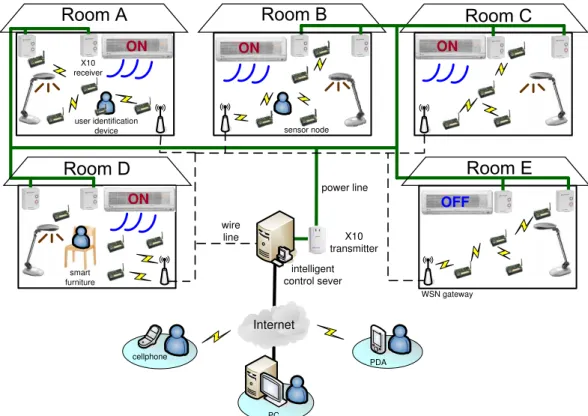
3.1 System Architecture
The architecture of our iPower system is illustrated in Fig-ure 1, which consists of many sensor nodes, several WSN gateways, an intelligent control server, some power-line control devices, and user identifications devices. Below, we describe the functions of each component separately.
• Sensor nodes: In each room, we deploy sensor nodes to monitor the environment. These nodes will form multi-hop WSNs to collect information in the rooms. In our current prototype, three types of sensing data can be collected, including light, sound, and temper-ature. An event is defined when the sensory input is higher or lower than a predefined threshold. To con-serve the energy of sensor nodes, reporting of events is reactive, in the sense that a node will report its sensing data only when some predefined events oc-cur. Different events can be combined to describe a room’s condition. For example, a low temperature (or a high brightness) together with some sound events in a room may indicate that the corresponding electrical appliances are turned on to serve users in that room;
Internet cellphone PC PDA intelligent control sever X10 receiver X10 transmitter sensor node smart furniture user identification device wire line ON ON ON OFF ON WSN gateway power line
Figure 1: System architecture of the iPower. indicate that users in that room are moving around;
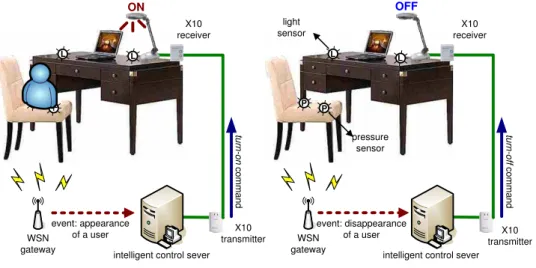
and a low temperature (or a high brightness) with no sound event for a certain amount of time may indi-cate that the air conditioners (or lights) in that room are unnecessarily turned on because no one is in the room. We can include more types of sensors to provide more intelligence. For example, as shown in Figure 2, a smart desk may include some pressure sensors un-derneath the cushion of a chair and some light sensors nearby the lamp on the desk. When someone is sit-ting on the chair, such an event can be detected by the pressure sensors, and the system can adjust the lamp according to the light degree nearby the lamp. When the user leaves the chair, the pressure sensors can detect the disappearance of the user and make en-ergy conservation decision by notifying the server to turn off the lamp.
• WSN gateways: The set of sensor nodes in each room will form a WSN. For each WSN, there is a WSN gateway. A WSN gateway has a wireless inter-face to communicate with sensor nodes and a wire-line interface to communicate with the intelligent control server. It has four major functionalities: issuing com-mands to sensor nodes, gathering data from sensor nodes, reporting the room’s condition to the intelli-gent control server, and maintaining the WSN. Specif-ically, the gateway will notify sensor nodes in the WSN to begin collecting environmental information when it receives a start command from the server. After
will determine the room’s condition and report to the server. In order to maintain the WSN, the gateway will periodically broadcast a heart-beat message to the network. A sensor node receiving such a message will reply an alive message to the WSN gateway. If the gateway does not receive any alive message from a sensor node for a predefined amount of time, it will notify the server that the node may be broken. • Intelligent control server: The intelligent control
server is used to collect the system’s status (e.g., rooms’ conditions and sensors’ states) and to perform power-saving decisions. It maintains a database of user profiles and periodically checks the states of elec-tric appliances in each room. It will decide whether to turn off an electric appliance in a room accord-ing to the sensory data collected from that room. The server can also adjust the electric appliances in a room according to the profiles of users in that room. Such decisions or adjustments are achieved by sending commands through the power-line control devices to turn off or adjust electric currents of the correspond-ing electric appliances. The server also provides user interfaces to allow users to maintain the iPower sys-tem. In particular, users can modify their profiles and obtain the system’s status through remote devices. • Power-line control devices: The power-line
con-trol devices allow the system to turn on/off or ad-just the electric currents of appliances. In our
cur-WSN gateway
(a) the user sits on the chair (b) the user leaves
light sensor pressure sensor OFF event: disappearance of a user tu rn -o ff c o m m a n d WSN gateway P P ON event: appearance of a user tu rn -o n c o m m a n d
intelligent control sever intelligent control sever X10 transmitter X10 receiver X10 receiver X10 transmitter L L L L P P
Figure 2: The “smart desk” scenario. by SmartHome (2006). Such devices contain one X10
transmitter and several X10 receivers. The X10 trans-mitter can talk to X10 receivers via power lines. In the iPower system, the X10 transmitter is connected to the control server to transmit the server’s commands. • User identification devices: The user identifica-tion devices are portable devices that can be carried by users so that the system can determine users’ IDs and retrieve their profiles. It can be any identifica-tion device. In this work, we simply use the processor board of our sensor platform (without sensors) for user identification. When a user enters a room, his/her user identification device will join the WSN in that room and provide its ID to the server via the WSN gateway.
3.2 Energy Conservation Scenarios
Next, we give five scenarios to demonstrate how the iPower system works in an intelligent building. Let us consider the five rooms in Figure 1.
• Room A: electric appliances are turned on and somebody is in the room (with a user identi-fication device). In this case, since the system can detect that the room is occupied, energy conservation commands will not be issued. So the electric appli-ances in room A will remain on.
• Room B: electric appliances are turned on and somebody is in the room (without a user iden-tification device). In this case, energy conserva-tion commands will be given depending on whether some events (such as sound events) indicating that the room is occupied can be detected or not. If there are such events, the electric appliances will remain on. Without such events, some signals (such as beeps or blinking lights) will be triggered to warn users in that
the system that the room is occupied (such as mak-ing some noise by clappmak-ing, covermak-ing any sensor with a light sensor to change its light reading, or switching on or off any electrical appliance that is under con-trol of the iPower system). As long as any of such events can be detected, the server can realize that the room is still in use and thus will not turn off the elec-tric appliances. Note that to reduce bothering users too much, the interval to warn users next time will be increased in an exponential manner after each in-tentional event being generated by users in that room. Further, after several warning signals without success, the system will stop trying (to make energy conserva-tion decisions) for a long period of time.
• Room C : electric appliances are turned on but nobody is in the room. In this case, since sen-sor nodes have detected a low temperature, a high brightness, and no sound event for some while, the WSN gateway will report to the control server that this room is abnormal, implying that electricity may be wasted in room C. The server will then send an alarm message to room C, which triggers the beepers attached to sensor nodes. These beeps are used to an-nounce that the system will turn off air conditioners and lights in room C in a few minutes. Alternatively, we can blink lights on and off to signal users that ap-pliances in that room will be turned off soon. This is to avoid our system to make wrong decisions. Since there is no one in the room, the server will turn off these appliances after timeout to conserve energy. • Room D: electric appliances are turned on in
the room with smart furniture. If there is smart furniture in the room, they can help detect the exis-tence of people in that room. For example, if there is a person sitting on a smart chair, the system will keep on reporting that someone is on the chair, so
Internet
PC WSN gateway
sensor node
1. start command 2. event-driven query 4. normal/abnormal 7 . tu rn -o ff c o m m a n d
5. alarm signal 6. beeps command
electric appliance user identification device 8 (b) sy stem con figu ra tion 8 (a ) u s e r I D 8(c ) eve nts ofh um an beh avi ou rs 3. report event 6 . b lin k c o m m a n d
Figure 3: Message flows in the iPower system. the smart furniture is not in use, then the scenario in room B may be applied.
• Room E : electric appliances are turned off. In this case, the WSN gateway will report to the server that the room is normal so the server will not take any action.
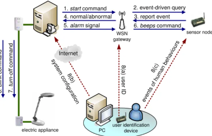
3.3 System Operations and Message Flows
Figure 3 illustrates the message flows and the interaction of system components in the iPower system. The details are discussed below.
1. The control server starts checking the usage of electric appliances in a room by sending a start message to the WSN gateway in that room. Checking can be done periodically or at predefined time, according to the system configuration file.
2. On receiving the start message from the server, the WSN gateway will notify its sensor nodes by issuing some event-driven queries to collect information from the environment. The WSN gateway then sets a timer to wait for sensing reports from sensor nodes. 3. When a sensor node detects any event (such as a low
temperature or a high brightness), it will report its sensing data to the WSN gateway.
4. If the WSN gateway receives any sensing report and any human behavior report from step 3 before its timer expires, it can determine the room’s status ac-cording to the following rules:
(a) If any piece of smart furniture reports that some-one is using it (e.g., the case in Figure 2(a)), the WSN gateway will report a normal status to the server. However, if it is reported that users leave the smart furniture, the WSN gateway will re-set its timer and go back to step 2 to repeat the
(b) If sensors report any human behavior (such as sound events or change of light readings), the WSN gateway will report a normal status to the server. However, it will also notify the existence of people to the server so that the system will check this room’s status later on.
(c) Otherwise, the WSN gateway will report an ab-normal status to the server to indicate that the electric appliances in the room may be turned on unnecessarily.
5. When the server receives an abnormal report from the WSN gateway, it will warn the people (if any) in the corresponding room by sending an alarm message to the WSN gateway.
6. Once receiving the alarm message, the WSN gateway will instruct one of its sensor nodes to turn on its buzzer to generate a beeping sound. Alternatively, the server can send a blink command to the X10 receiver to blink any light on and off for a short period of time. These actions are used to notify people in the room that the server will turn off the electric appliances after a short period of time (e.g., ten minutes). 7. If the server does not receive any human behavior
event from the room after a predefined period of time, it will know that there is no one in that room and thus turns off the electric appliances by sending a turn-off command to the X10 receivers in that room.
8. If there is any user in the room hearing the beeping sound or seeing blinking light, he/she can notify the server that the room is still in use by any of the fol-lowing three methods:
(a) If the user has carried a user identification device, the device will directly inform the server (via the WSN gateway) his/her ID. In this case, the user does not need to take any action.
(b) If the user can access the Internet, he/she can login the web page of the iPower system to set up the next checking time of this room so that the server will not disturb the user before he/she leaves the room.
(c) Otherwise, the user can make some intentional events by changing the room’s environment, such as making some noise by clapping or turning off and then turning on any light. In this way, sensor nodes will detect an unusual sound or change of light degree and thus report these events to the WSN gateway.
According to these reports, the WSN gateway can notify the existence of users to the server and thus the system will back off and check the room’s status later on. The next checking time can be set manually by users, by any default value (such as one hour), or in any typical exponential
<? xml version="1.0" encoding="UTF-8" ?>
-<User> <Id>007</Id>
<Name>HSCC</Name>
-<Attribute>
<Name>temperature</Name> <Value type="Float"/>
<Range max="28"min="25">true</Range> </Attribute>
-<Attribute>
<Name>light</Name>
<Value type="Float">70</Value> <Range max="0"min="0">false</Range> </Attribute>
</User>
Figure 4: An example of the user profile.
3.4 Personalized Services and User Profiles
The iPower system also provides personalized services in which electric appliances can be automatically adjusted to satisfy users’ preference. In particular, each user can spec-ify his/her favorite temperature and brightness. When a user enters a room, the iPower system can adjust the air conditioners and lights to meet the user’s preference. To achieve this goal, the user has to create a profile in the server’s database and carry a user identification device when entering our system. The user’s location is deter-mined by the WSN gateway which collects the user’s ID.
In our current implementation, we follow the format of XML (2006) to describe user’s profiles. The current def-inition is illustrated in Figure 4. Specifically, the profile includes user’s ID, name, and several attributes with the user’s favorite temperature and brightness. For example, Figure 4 indicates that user’s preference temperature is from 25oC 28oC and light is 70 lux.
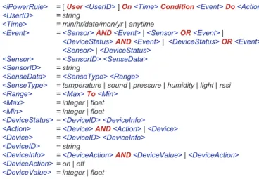
3.5 Events and Actions
One of the main components of iPower is its automatic rules. A rule can be composed of time, events and actions. A rule can be event-driven or time-driven. Actions can be triggered by simple events or compound events, where the latter are combinations of multiple simple events. For example, when someone is sitting on a smart chair near a smart desk with a low light degree, to automatically turn on the lamp on the desk, we need to combine events from pressure sensors and light sensors. Note that compound events can be combined through logical operations, such as “AND” and “OR”.
In Figure 5, we list the definition of iPower’s rules, which are written in the format of EBNF (Extended Backus-Naur Form) (Sebesta, 1999) recursive grammar. Each iPower’s rule defines for a certain User, when some Time and some Conditions are matched, the corresponding actions to be taken. Terms quoted by [· · ·] are optional. For example, when <UserID> in a rule is not specified, it means that anyone can match this rule. Figure 6 shows the rules for rooms A, C, and D in Figure 1. Note that here we use
<iPowerRule> <UserID> <Time> <Event> <Sensor> <SensorID> <SenseData> <SenseType> <Range> <Max> <Min> <DeviceStatus> <Action> <Device> <DeviceID> <DeviceInfo> <DeviceAction> <DeviceValue>
= [User<UserID>]On<Time>Condition<Event>Do<Action>
= string
= min/hr/date/mon/yr | anytime
=<Sensor>AND<Event>|<Sensor>OR<Event>|
<DeviceStatus>AND<Event>|<DeviceStatus>OR<Event>| <Sensor>|<DeviceStatus>
=<SensorID> <SenseData>
= string
=<SenseType> <Range>
= temperature | sound | pressure | humidity | light | rssi =<Max>To<Min>
= integer | float = integer | float
=<DeviceID> <DeviceInfo>
=<Device>AND<Action>|<Device>
=<DeviceID> <DeviceInfo>
= string
=<DeviceAction>AND<DeviceValue>|<DeviceAction>
= on | off = integer | float
Figure 5: The iPower’s EBNF-like recursive grammars. Room A:
UseruserID_1
Onanytime
Condition( sensorID_1 temperature 28 To 50 )
Dodevice_aircon on
Room C:
Onanytime
Condition( sensorID_2 rssi 0 To 40 ) AND ( sensorID_2 rssi 80 To 100 ) AND ( device_lamp on )
Dodevice_lamp off
Room D:
Onanytime
Condition( sensorID_3 light 0 To 20 ) AND ( sensorID_4 pressure 10 To 100 )
Dodevice_lamp on
Figure 6: Examples of the iPower’s rules.
to indicate that a user’s badge is within the range of a WSN.
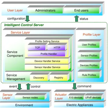
3.6 Protocol Stack
To implement the iPower system, we have designed a pro-tocol stack in Figure 7, which consists of the following layers:
• User layer: The user layer defines how a user can access the system through the user interface. Here we consider two kinds of users: administrators and end users. An administrator can add or remove equip-ments (e.g., electric appliances, sensor nodes, and power-line control devices) in the system, change their attributes and profiles, and manage end users. An end user can only create and modify his/her user profile. • Service layer: The service layer defines the rules by
which the system provides and manages its services. We follow the interface defined in OSGi (1999), which is a service-oriented architecture for networked sys-tems. An OSGi platform provides a standardized, component-oriented computing environment for the cooperating networked services. Using this architec-ture can help reduce complexity to build and main-tain applications. Following OSGi, the service layer is separated into service component and service
manage-User Layer Administrator End users
User Layer Administrators End users
Sensor Layer
Environment Sensor nodes
configuration status
event control command
Intelligent Control Server
Actuator
X10 devices UPnP devices
Actuator Layer X10 devices Electric Appliances UPnP devices Profile Layer Service Layer Service Component Service Management Rule Profiles TCP HTTP Profile Handler
Device Handler Service
Sensor Handler Service Profile Setting Service
Discovery Registry Devices Profiles Sensor Profiles User Profiles Profile Layer Service Layer Service Component Service Management Rule Profiles TCP HTTP Profile Handler
Device Handler Service
Sensor Handler Service Profile Setting Service
Discovery Registry
Devices Profiles Sensor Profiles User Profiles
Figure 7: Protocol stack of the iPower system. by the system, while the latter provides a management mechanism to maintain these services. In our current implementation, three service components are defined, including profile setting service, device controller ser-vice, and sensor handler service. The profile setting service is used to create and modify a profile, while the device controller service and sensor handler ser-vice are used to control the power-line control deser-vices and sensor nodes, respectively. To manage services, a new service component must be first registered to the server. The administrator can obtain the statues of all service components in the system by the service discovery mechanism.
• Profile layer: The profile layer maintains all pro-files for users, sensor nodes, power-line control devices, and rules. The sensor profiles describe the locations and sensing types of sensor nodes. The device pro-files describe the electric appliances controlled by the power-line control devices. Finally, the rule profiles define how the components in the iPower system in-teract with each other. All profiles are depicted in the format of XML.
• Sensor layer: The sensor layer controls the actions of sensor nodes. These actions include executing com-mands from the WSN gateway (such as to detect events and to generate beeping sounds) and report-ing sensreport-ing data to the WSN gateway.
• Actuator layer: This layer provides an abstraction of electric appliances to upper layers (i.e., service layer and profile layer). In our implementation, we choose
Through these protocols, we can turn on, turn off, and adjust the electric currents of appliances.
4 Implementation Details
4.1 Hardware Specification
We use MICAz (2005) as sensor nodes. The MICAz is a 2.4 GHz, IEEE 802.15.4-compliant module that enables low-power operations and offers a data rate of 250 kbps with a DSSS radio. Each sensor node has a sensing board that can collect sensing data from their surroundings, in-cluding light, sound, and temperature. More sensors can be added on the board to increase the sensing capabilities. Each sensor node also has a buzzer to generate a beeping sound when they are commanded by a WSN gateway.
For the power-line control devices, we adopt the X10 products by SmartHome. The X10 devices consist of X10 transmitters and X10 receivers. They can communicate with each other by the X10 communication protocol, which encodes messages on the electric signal with a frequency of 60 Hz. With the X10 communication protocol, an X10 transmitter can send commands to an X10 receiver through a power line. To control electric appliances, we connect one X10 transmitter to the server via an RS-232 interface and connect all electric appliances with X10 receivers. Each X10 receiver has a unique address and at most 256 ad-dresses can be selected.
4.2 Design of The Intelligent Control Server
The intelligent control server is the core of our iPower sys-tem. Figure 8 illustrates the design of the server. The implantation details are discussed below.
1. An administrator can add a sensor profile or a device profile through the profile setting component. Re-lated information such as sensing types and device attributes can be created in the profile database. 2. An administrator can interact with the profile
inter-face to create rules through the rule setting compo-nent.
3. A gateway can report environment information through the sensing data I/O interface.
4. The decision handler combines the user profiles, rules, and sensing data to generate proper actions.
The actions are sent to the action handler, which can generate commands to X10 devices or sensor nodes.
4.3 User Interface
We provide a user interface to manage the system and al-low users to create their profiles at the server, as shown in Figure 9. The user interface has an object area, a
moni-Rule Setting Profile Setting TCP/HTTP TCP/HTTP Action Handler Sensing Data I/O Decision Handler Rule Database Profile Database Action Profile Interface User Profile Sensor Profile Device Profile Rules X10 command
Intelligent Control Server
X10 transmitter X10 receiver
power line WSN gateway
Figure 8: Design of the intelligent control server. interface to deploy all devices in a room, including WSN gateways, sensor nodes, electric appliances, and X10 de-vices. This area also allows users to start or stop the sys-tem. In the monitor area, the administrator can visualize the deployment of sensor nodes and devices. He/She can add new objects in the room by dragging objects from the object area to the monitor area. The monitor area also shows the network topology and electric appliance in the room. In the status area, the administrator can observe the attributes and the current status of each sensor node.
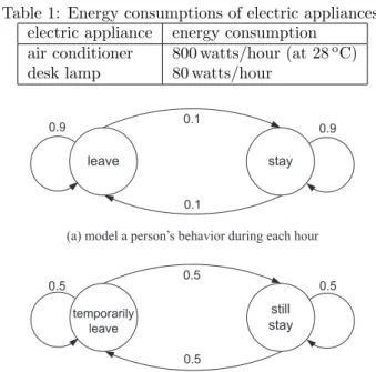
5 System Evaluation
In this section, we present some simulation results to eval-uate the system performance. We consider the energy con-sumption of an office with five people, one air conditioner, and five desk lamps, where each lamp is owned by one person. Table 1 lists the energy consumptions of differ-ent electric appliances. For the air conditioner, we assume that it will spend extra 100 watts when the temperature is decreased by 1oC. A two-state discrete Markov model (Kleinrock, 1975) is used to model a person’s behavior dur-ing every hour, as shown in Figure 10(a). A person can be either in one of the two states: leave or stay. When a person is in a leave state, the corresponding desktop lamp will be turned off. We use another Markov model to model the detailed behavior of a person when he/she in a stay state, as shown in Figure 10(b). In particular, during
Figure 9: The user interface at the intelligent control server.
Table 1: Energy consumptions of electric appliances. electric appliance energy consumption
air conditioner 800 watts/hour (at 28oC)
desk lamp 80 watts/hour
leave stay still stay temporarily leave 0.5 0.5 0.5 0.5 0.9 0.1 0.9 0.1
(a) model a person s behavior during each hour
(b) model a person s detailed behavior during each twenty minutes, ,
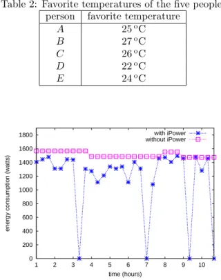
Figure 10: Two-state discrete Markov models. “still stay” in the office or “temporarily leave” the office. When the person decides to temporarily leave the office, his/her own desktop lamp will remain on if the iPower sys-tem is not applied. Table 2 lists the favorite sys-temperatures of the five people. When there are two or more people in the office, the temperature of the air conditioner will be adjusted to the average of favorite temperatures of those people in the office. Note that without iPower, we only adjust the temperature of the air conditioner when people enter the office.
peo-Table 2: Favorite temperatures of the five people. person favorite temperature
A 25oC B 27oC C 26oC D 22oC E 24oC 0 200 400 600 800 1000 1200 1400 1600 1800 10 9 8 7 6 5 4 3 2 1
energy consumption (watts)
time (hours)
with iPower without iPower
Figure 11: Energy consumptions during 10 hours.
0 5000 10000 15000 20000 25000 30000 35000 40000 45000 5 4 3 2 1
energy consumption (watts)
number of people with iPower
without iPower
Figure 12: Total energy consumptions with different num-bers of people.
the energy consumption of the office is always higher than 1500 watts, even when there is no person in the office (i.e., hours 3, 7, 9, and 10). This is because when all people temporarily leave the office, the air conditioner and some desk lamps are still turned on. On the other hand, the iPower system can detect such situation and thus prop-erly turn off some electric appliances to conserve energy. Figure 12 compares the total energy consumptions of the office with different numbers of people in the simulation. As can be seen, our iPower system can save approximate
6 Conclusions and Discussions
In this work, we have proposed the iPower system designed for energy conservation in an intelligent building and provi-sion of personalized services for environment control. The iPower system can detect if there is possible waste of tricity by WSNs and then turn off these unnecessary elec-tric appliances via the X10 power-line control devices with a user-friendly design. The iPower system also provides personalized services in which electric appliances can be automatically adjusted to satisfy users’ requirements. We have presented the design and implementation details of iPower. Prototyping experiences and design issues are also given in this paper.
The prototyped iPower system can be further improved in several ways. First, since the X10 protocol is somewhat slow and sometimes unreliable, in the future we plan to replace X10 by INSTEON (2007), which could be more reliable and could transmit at a higher speed. Also, we are considering integrating other intelligent furniture into our system. Below, we point out several important design issues that deserve attention.
• Conflicting profiles: When two or more people are in the same room, their profiles may conflict with each other since each person may have different require-ment or preference in temperature and light. To solve the profile-conflicting problem, we propose to assign a weight to each user and adopt the weighted aver-age to determine the desired degrees of temperature and light. For example, suppose that two users have favorite temperatures of 23oC and 26oC in their pro-files, and their weights are 3 and 2, respectively. Then the desired temperature will be
3
3 + 2× 23 + 2
3 + 2 = 24.2 oC.
Note that the weight assignments can depend on the application requirements or user priorities.
• Privacy and security: In the iPower system, the complete user profiles are stored in the control server. A user identification device only needs to transmit its ID to the control server to find out the corresponding profile. Thus, the personal information will not be exposed through the user identification device. The ID of a user can be represented either by the address or the network interface card or a higher-level identity. Since the network address must be in clear text in any communication, it is insecure to use such addresses as user IDs. So, the latter approach is preferred (which can be protected by any encryption algorithm). • Message reliability: Most of the signalling messages
in Figure 3 require an acknowledgement mechanism to guarantee their delivery. Unfortunately, the X10 devices do not support such acknowledgement mech-anism. To solve this problem, we can enforce sensor
to check whether the X10 devices have successfully deliver the commands from the control server. For example, in Figure 3, suppose that sensor nodes re-port that there is nobody in the room and thus the control server will send a command to the X10 re-ceiver to turn off the electric appliance (e.g., the desk lamp). If the turn-off command is lost due to channel errors in the power-line, the sensor node can maintain a timer to check whether the command from the con-trol server has been reflected from its reading related to the desk lamp. Therefore, the message loss problem on X10 can be resolved.
• Incorrect sensing readings: Due to environmen-tal noises or errors, the readings of sensor nodes may not be accurate. This may mislead the control server to make incorrect decisions. To solve this problem, we can apply the solutions in Branch et al. (2006); Zhuang et al. (2007); Sheng et al. (2007) to alleviate the effects of these inaccurate sensing readings. • Environmental factors: Some environmental
fac-tors like sunlight can be considered to help conserve more energy. For example, the work in Singhvi (2005) suggests adjusting lamps according to users’ require-ments and the sunlight. Similarly, we can apply this extension in our system.
ACKNOWLEDGMENT
Y. C. Tseng’s research is co-sponsored by Taiwan MoE ATU Program, by NSC grants 93-2752-E-007-001-PAE, 96-2623-7-009-002-ET, E-009-058-MY3, 95-2221-E-009-060-MY3, 95-2219-E-009-007, 95-2218-E-009-209, and 94-2219-E-007-009, by Realtek Semiconductor Corp., by MOEA under grant number 94-EC-17-A-04-S1-044, by ITRI, Taiwan, by Microsoft Corp., and by Intel Corp.
REFERENCES
Gassmann, O., Meixner, H., Hesse, J.W.G.J. and Gopel, W. (2001) ‘Sensors in intelligent buildings: sensors ap-plications’, Wiley-VCH.
Schulzrinne, H., Wu, X., Sidiroglou, S. and Berger, S. (2003) ‘Ubiquitous computing in home networks’, IEEE Communications Magazine, Vol. 41, No. 11, pp.128–135. Rosenberg, J., Schulzrinne, H., Camarillo, G., Johnston, A., Peterson, J., Sparks, R., Handley, M. and E. Schooler (2002) ‘SIP: session initiation protocol’, IETF RFC 3261.
Das, S.K., Cook, D.J., Battacharya, A., Heierman. III, E.O. and Lin, T.Y. (2002) ‘The role of prediction algo-rithms in the mavhome smart home architecture’, IEEE
Wang, X., Dong, J.S., Chin, C.Y., Hettiarachchi, S.R. and Zhang, D. (2004) ‘Semantic space: an infrastructure for smart spaces’, IEEE Pervasive Computing, Vol. 3, No. 3, pp.32–39.
Helal, S., Zabadani, W.M.H.E., King, J., Kaddoura, Y. and Jansen, E. (2005) ‘The gator tech smart house: a programmable pervasive space’, IEEE Computer, Vol. 38, No. 3, pp.50–60.
SmartHome (2006) X10-1132B.
Available at: http://www.smarthome.com/. W3C (2006) Extensible markup language (XML).
Available at: http://www.w3.org/TR/REC-xml/. Sebesta, R.W. (1999) ‘Concepts of programming
lan-guages, 4th ed.’, Addison-Wesley. OSGi Alliance (1999).
Available at: http://www.osgi.org/. UPnP Forum (1999).
Available at: http://www.upnp.org/. Crossbow (2005) MOTE-KIT2400.
Available at: http://www.xbow.com/.
Kleinrock, L. (1999) ‘Queueing systems, volume 1: theory’, John Wiley & Sons, Inc..
INSTEON (2007).
Available at: http://www.insteon.net/.
Branch, J., Giannella, C., Szymanski, B., Wolff, R. Kar-gupta, H. (2006) ‘In-network outlier detection in wire-less sensor networks’, Proceedings of IEEE International Conference on Distributed Computing Systems.
Zhuang, Y., Chen, L., Wang, X. S. and Lian, J. (2007) ‘A weighted moving average-based approach for cleaning sensor data’, Proceedings of IEEE International Confer-ence on Distributed Computing Systems.
Sheng, B., Li, Q., Mao, W. and Jin, W. (2007) ‘Outlier detection in sensor networks’, Proceedings of ACM In-ternational Symposium on Mobile Ad Hoc Networking and Computing, pp.219–228.
Singhvi, V., Krause, A., Guestrin, C., Garrett, J. and Matthews, H. S. (2005) ‘Intelligent light control us-ing sensor networks’, Proceedus-ings of ACM International Conference on Embedded Networked Sensor Systems, pp.218–229.
![Fig. 1. The 1-coverage sensor placement method proposed in [15]: (a) the case of r c < √](https://thumb-ap.123doks.com/thumbv2/9libinfo/8596202.189948/33.892.457.820.309.584/fig-coverage-sensor-placement-method-proposed-case-lt.webp)