國
立
交
通
大
學
生醫工程研究所
碩
士
論
文
時序特徵分類與投票之三選項腦機界面
系統
Three-choice Brain-Computer Interface System through
Classification and Voting of Temporal Features
研 究 生:陳亮維
時序特徵分類與投票之三選項腦機界面系統
Three-choice Brain-Computer Interface System through Classification
and Voting of Temporal Features
研 究 生:陳亮維 Student:Liang-Wei Chen
指導教授:陳永昇 Advisor:Yong-Sheng Chen
國 立 交 通 大 學
生 醫 工 程 研 究 所
碩 士 論 文
A ThesisSubmitted to Institute of Biomedical Engineering College of Computer Science
National Chiao Tung University in partial Fulfillment of the Requirements
for the Degree of Master
in
Computer Science
June 2009
Three-choice Brain-computer Interface System
through Classification and Voting of Temporal
Features
A thesis presented
by
Liang-Wei Chen
to
Institute of Biomedical Engineering
College of Computer Science
in partial fulfillment of the requirements for the degree of
Master
in the subject of
Computer Science
National Chiao Tung University Hsinchu, Taiwan
Three-choice Brain-computer Interface System through Classification and Voting of Temporal Features
Copyright c 2009
by
摘要 腦機界面系統(BCI)提供一個單靠腦部活動來取代平常使用的肌肉做為和外界 溝通的管道。而腦電波圖(EEG)廣泛的應用在腦機界面系統中。透過記錄和分析 使用者執行特定任務時的腦部活動,可以將分析過後的結果轉換成對應的指令而 達到像是控制義肢或指標、打字或回答問題。時至今日,像是運動想像腦機界面 或事件相關腦機界面等許多腦機界面系統蓬勃發展。在現存的腦機界面研究中, 以 P300 為基礎的腦機界面因穩定且不需預先訓練受試者的優點,因而被廣泛研 究。 為了達到降低訓練時間和降低使用者的負擔,我們使用一個三選項的界面實作 以 P300 為基礎腦機系統。我們並使用一個經典的 P300 分析方法步進線性鑑別分 析(Stepwise linear discriminant analysis)做為特徵選取和分類。並提出一 投票策略來達到系統可自動且即時的依使用者做調整,以增進線上系統的效能。 更具體來說,我們結合步進線性鑑別分析和活動窗口(moving window)來產生時 序特徵做投票。透過這些時序特徵我們可以決定門檻值使得線上系統可以在維持 一定的分辨率的條件下動態決定結果。因此,我們可以增進線上系統溝通的效能 和效率。 三個健康的受試者被邀請參與離線和線上的實驗。研究結果顯示,我們的系統 比 Sellers 和 Donchin 在 2006 所發表的四選項腦機系統有更好的效能。在離線 分析我們在 83.4%的分辨率下達到 7.7 bits/min 的轉移率,而當線上系統達到 5.23 bit/min 的轉移率時則有 100%的分辨率。這些結果都證明了比四選項系統 在 97%的分辨率下達到 1.8 bit/min 有更好的效能,也顯示了適應性在腦機界面 系統上的優點。
Abstract
Brain-computer interface (BCI) provides a channel to communicate with external world only through cerebral activity, thus replacing the normal pathway of communication by using muscles. The electroencephalography (EEG) is commonly used in the BCI system. When a subject is performing specific tasks, the EEG signals induced by the subject’s neuronal activities are recorded and analyzed. Then, the analyzed EEG signals will be translated to the corresponding commands to control prosthesis or cursor, spell words, answer questions. Nowadays, there are many development of BCI systems such as Motor-imagery based BCI systems, ERP-based BCI systems. In the existing BCI studies, P300-based BCI systems are commonly conducted, because P300 ERP can be reliably measured without initial user training. To reduce training time and subjects’ burden, our P300-based BCI system is implemented by using a three-choice paradigm. We use a typical P300 analysis method, stepwise linear discriminant analysis (SWDA) for feautre selection and classification. To improve the system, we propose a ”voting strategy” to automatically make the online system adaptable to users. More specifically, we combine SWDA with moving window to produce the temporal features for voting. Through the temporal features which can decide the threshold, the online system can dynamically make decision while maintaining the accuracy of classification. In this way, we improve the performance and efficiency of communication in online BCI system. Three able-body subjects are recruited to participate in the offline experiments, and seven able-body subjects are recruited to participate in online experiments. The results of this study present better performances than those in the four-choice offline system provided by Sellers and Donchin (2006). In offline analysis, the transfer rates can be achieved up to 7.7 bits/min with an accuracy of 83.4%, while the transfer rates of online testing can be achieved up to 5.28 bits/min with an accuracy of 100%. These results suggest that the performances of our system are better than four-choice system in which transfer rate is 1.8 bits/min with accuracy of 97%, thus indicating the advantage of the adaptability in BCI system.
致謝 碩士班這二年的研究生活,首要感謝的是指導教授陳永昇老師和陳麗芬老師, 陳永昇老師除了在研究上極有耐心和熱忱的給予我指導,讓我學到如何有系統且 有效率的完成進度,並了解到在處事態度上,認真細心的重要。生活上,老師總 是不吝於關心我們的生活和心理狀況。讓我們在研究上更加順利。也感謝梁勝富 教授和林昌宏醫師在論文上的審察,以及口試時的建議和指導。 這段實驗室的日子裡,很高興有這麼多伙伴的陪伴。搞笑的乙慈、陽光的發哥、 阿呆的郁萱、瘋瘋的 sheep 還有神秘的育宏,平時的打打閙閙,低潮時的互相心 理輔導,瓶頸時的腦力激盪,讓研究生活一直都好開心。也感謝所有無怨無悔當 我受試者的勇者們,柏志、筱苑、億婷、清偉和乙豪,真的很謝謝你們。還有謝 謝慧玲、嘉修和詠成,你們的關心是我學習上很大的幫助。另外要特別感謝的是 士瑋,從我入學到畢業,即使當兵仍持續的關心我的研究狀況,口試時有你坐在 台下,真的讓我安心許多。 最感謝還是筱雯,謝謝妳沒日沒夜的聽我哀嚎,並在最重要的階段給我最大的 幫助,沒有妳我也無法順利完成這本論文。也謝謝我的家人總是在我低潮時給我 暖暖的叮嚀和擁抱,是讓我堅持下去的最大動力。
Contents
List of Figures vii
List of Tables ix
1 Introduction 1
1.1 Motivation . . . 2
1.2 Electroencephalography . . . 3
1.2.1 Introduction to Electroencephalography . . . 3
1.2.2 Basic Analysis of Electroencephalography . . . 4
1.3 Brain-computer Interface . . . 5
1.4 Event-related Potentials . . . 6
1.5 Thesis Overview . . . 9
2 Survey of Brain-computer Interface 11 2.1 Categories of Brain-computer interface systems . . . 12
2.2 Basic components in BCIs . . . 13
2.3 Present-day BCI systems . . . 15
2.3.1 ERP-based BCI . . . 15
2.3.2 Motor-imagery based BCI . . . 16
2.4 Review of P300-based BCI systems . . . 17
2.5 Limitations . . . 19
2.6 Key-issues in BCI systems . . . 20
2.7 Thesis scope . . . 22
3 Proposed P300-based BCI System 23 3.1 Data preprocessing . . . 24
3.2 Stepwise linear discriminant analysis . . . 24
3.2.1 Introduction . . . 24
3.2.2 Linear regression . . . 25
3.2.3 Forward selection method . . . 26
3.2.5 Stepwise procedure . . . 27 3.3 Voting . . . 28 3.3.1 Moving window . . . 29 3.3.2 Voting strategy . . . 31 3.4 Performance evaluation . . . 33 3.4.1 Bootstrap method . . . 33 3.4.2 Bit rate . . . 33 4 Experiments 35 4.1 Offline . . . 36 4.1.1 Experiment paradigm . . . 36 4.1.2 Experiment setup . . . 37 4.1.3 Experiment result . . . 39 4.2 Online . . . 46 4.2.1 Training . . . 46
4.2.2 Online adaptive strategy . . . 47
4.2.3 Feedback . . . 48 4.2.4 Experiment result . . . 49 4.3 Summary . . . 51 5 Disscusion 53 6 Conclusions 61 Bibliography 65
List of Figures
1.1 EEG measuring devices . . . 4
1.2 The international 10-20 system . . . 5
1.3 The P300 ERP . . . 7
2.1 Speller and Virtual apartment . . . 17
2.2 Cursor control and brain-controlled wheelchair . . . 18
3.1 Regression fitted straight line . . . 25
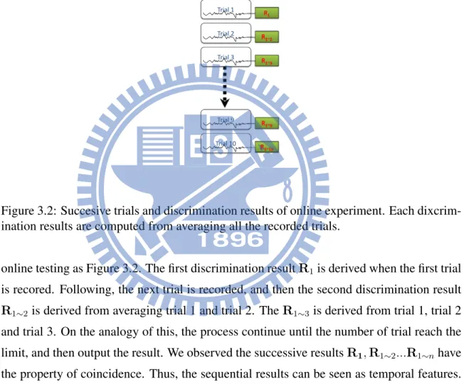
3.2 Succesive trials and discrimination results of online experiment . . . 29
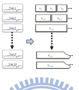
3.3 Using a moving window to produce the combination results of the trials . . 30
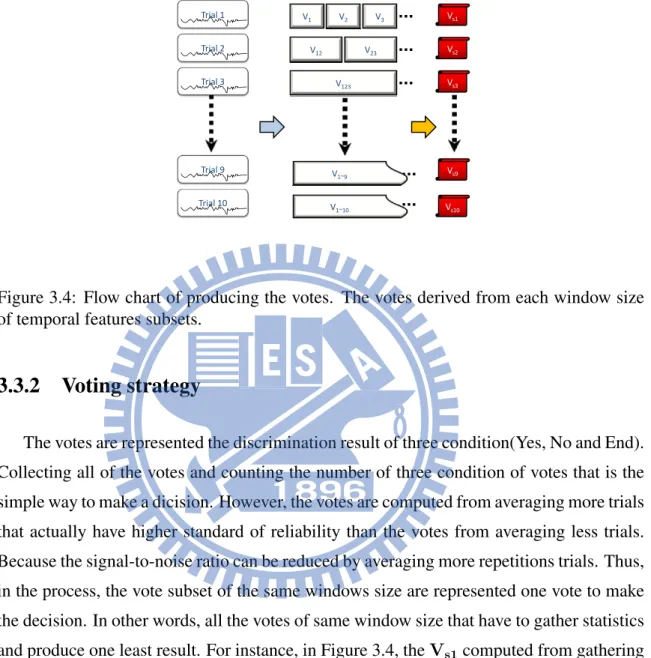
3.4 Flow chart of producing the votes . . . 31
3.5 Flow chart of bootstrap . . . 33
3.6 Bit rate in different number of possible selections . . . 34
4.1 Experiment paradigm . . . 36
4.2 No condition averaging data . . . 37
4.3 Seven channels (Fz, Fcz, Cz, Cpz, P3, Pz, P4) were used . . . 38
4.4 Result of voting under three condition of Subject 1 . . . 40
4.5 Result of voting under three condition of Subject 2 . . . 41
4.6 Result of voting under three condition of Subject 3 . . . 42
4.7 Result of online simulation of Subject 1. . . 44
4.8 Result of online simulation of Subject 2 . . . 44
4.9 Result of online simulation of Subject 3 . . . 45
4.10 Three condition averaging data of target. . . 46
4.11 Online system flowchart . . . 47
4.12 Onine result . . . 49
4.13 Onine result . . . 50
5.1 Feature points . . . 54
5.2 Three condition comparison . . . 55
5.3 Moving window based . . . 57
List of Tables
3.1 Percentage of votes in 10 successive trials . . . 32
4.1 Information transfer rate of offline analysis . . . 45
4.2 Information transfer rate of online testing . . . 51
5.1 Information transfer rate of Subject 1 . . . 58
Chapter 1
Introduction
In this first chapter we give some background knowledge to this thesis. We briefly introduce from the Electroencephalography to brain-computer interfaces to event-related potentials (ERPs). In Section 1.2 we give some introduction to Electroencephalography (EEG), so called brain wave. The measurement way, some basic analyses and researches are presented. In Section 1.3 we give a brief introduction to brain-computer interfaces (BCI). In Section 1.4, we give a description of the ERPs that can be used in BCI system. The detail of BCI systems will be provided in the next Chapter.
1.1
Motivation
Diseases like Amyotrophic Lateral Sclerosis (ALS) make patients being unable to com-municate with the external world through the normal pathway, such as talking or taping. However, their brain is still healthy, even thouhgh they have the paralyzed body. Nowa-days, to help those who suffer from diseases like ALS, the development of brain-computer interface can provide a new way to communicate with external world. In other words, a Brain-computer interface is defined as a communication system which does not depend on the brains normal output pathways of peripheral nerves and muscles. Specifically, subjects can communicate with the external world only with barin waves.
In order to provide a realistic application in daily life, a pratical brain-computer inter-face system should have real time response and felxibility in various situations. A real time BCI system, the so-called online BCI system, can facilitate subject to express ideas or to have direct communication with other people. In addition, a flexible online BCI system can adapt to differnt subjects, thus improving the efficiency of the system.
Even though the developement of BCI systems thrives in recent years, usability is still a debatable issue in BCI systems. For instance, subjects under some BCI systems have to move their eyes to gaze at differet stimulus in order to transmit commends. However, if dis-abled patients can move their eyes or even one muscle in a controlled way, other interfaces based on eye-gaze or EMG switch technology are more efficient than some existing BCI systems. Moreover, some systems require long subjects training time, and some may be only suitable for certain subjects. Thus, an online BCI system with short training time and
simple tasks can reduce subjects’ burden and make the system eazier to use. Consequently, if a practical online BCI system is established, it may be widely used. In this case, subjects are more willing to accept this system. Thus, this research project is of great worth.
1.2
Electroencephalography
1.2.1
Introduction to Electroencephalography
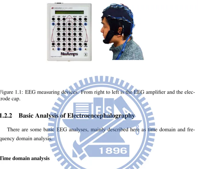
There exists various non-invasive techniques to monitor the brain activity such as func-tional Magnetic Resonance Imaging (fMRI), magnetoencephalography (MEG), and Elec-troencephalography (EEG). EEG is used to measure the electrical activity of the brain. This activity is generated by billions of nerve cells, called neurons. Each neuron is connected to thousands of other neurons, and the neurons send action potentials to other neurons when they are communicating. When we measure the EEG, we actually measure the combined electrical activity of millions of neurons on the cerebral cortex because the potential of a single neuron is too small to be measured. A typical EEG measuring device consists of sev-eral components, including EEG electrode cap that receives the electrical avtivity from the scalp, EEG amplifier that amplifys the signal, computers that record the data, and monitors that give the subjects visual stimulus. The devices are shown in Figure 1.1.
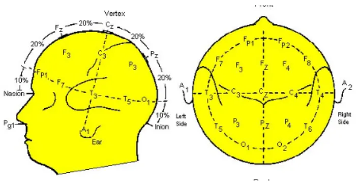
The EEG signal has a good temporal resolution, but it has a poor spatial resolution, which depends on the electrode number of an EEG electrode cap. The electrode layout on an EEG electrode cap has a international standtard called the international 10-20 system, as Figure 1.2 shows. When we are measureing EEG, we often put some single electrodes surrounding the eye. This is used to measure the electrical activity of eye movement and eye blinking, which is called EOG. This EOG contaminates the EEG signal badly, so by measuring it we can remove the trials that was affected. This processing is called EOG rejection.
When we use an EEG electrode cap to measure EEG, we have to fill each electrode with the electrolyte gel using a blunt needle. This makes the electrodes contact the scalp and lower the impedance. In an EEG experiment we often wait until all the electrodes have an impedence lower 3k ohm before we start the signal acquisition.
Figure 1.1: EEG measuring devices. From right to left is the EEG amplifier and the elec-trode cap.
1.2.2
Basic Analysis of Electroencephalography
There are some basic EEG analyses, mainly described here as time domain and fre-quency domain analysis.
Time domain analysis
Usually we use time domain analysis to observe an Event-related Potential (ERP). An ERP is a potential change in the EEG when a particular event or stimulus occurs. The potential change is time-locked and phase-locked, it is a very small potential change and can not be easily observed in a single trial. So we have to average a few trials to observe it. Because of the time-locked and phase-locked characteristic, by the averaging technique we can eliminate the random noise and enhance the signal-to-noise ratio (SNR). That is the common technique to observe an ERP. Another technique that is often used to sepa-rate these signals from background activity and noise is lowpass or bandpass filter. It is rereasonable because most of the energy of ERP is concentrated at low frequencies. Some well-known ERP-based BCI have employed filtering and averaging, including P100 in the Visual-evoked Potential (VEP), P300, N400, and Audio-evoked Potential (AEP).
Figure 1.2: The international 10-20 system. The ”10” and ”20” means the 10% and 20% interelectrode distance. The ’F’, ’C’, ’P’, ’O’, ’T’ represent with respect to frontal, central, parietal, occipital, temporal lobe. The odd number is placed in the left side and the even number the right side [3]
Frequency domain analysis
Frequency domain analysis are used to observe the changes in oscillatory activity. Such changed can be evoked by presentation of stimulus or by concentration of the subject on a specific mental task. Usually, the phase of oscillatory activity is not time-locked to the stimulus or to mental task of subject. Thus, time domain analysis technique cannot be used. Instead, frequency domain analysis are used to observe the oscillatory activity. For instance, SSVEP have band power in the harmonics of the visual stimulation frequency at occipital cortex. Fast Fourier transform can be used to estimate the band power as features. Another example in systems based on motor imagery, the bandpower in the mu and beta rhythm over the sensorimotor cortex is used as features.
1.3
Brain-computer Interface
Over the past few decades, the EEG has been used mainly for evaluation of neuro-logical disorders in the clinic and for the investigation of brain functions. Until recently, researchers found it possible to translate some specific EEG to commands. That is, people can communicate with others or control devices directly by their brain activity, without using any normal pathways of the peripheral nerves. This communication and control technique was then called Brain-computer Interface [22] . Among the methods to measure
electrical activity, MEG and EEG are more suitable for a BCI system because they can give the instantaneous continuous recording of brain activity. And EEG is even more suit-able because of the following advantages, the devices to measure EEG are more portsuit-able and cheaper, and we don’t have to be in a shielding room when measuring EEG. Although the EEG signal is having low spatial resolution compared to the others. Almost all BCI researches are using EEG signal nowadays.
A general BCI has many components. The BCI system goes through the data acquisi-tion, then some signal processing, followed by a command translaacquisi-tion, in the end output commands to communicate with others or to control cursors or devices. The details of a BCI system will be described in the next Chapter.
1.4
Event-related Potentials
Servel kind of internally or externally paced events will result in time-locked and phase-locked brain signals. Almost all of these kinds evoked activities have a more or less fixed time-delay to the stimulus. These time-locked and phase-locked called event-related po-tentials (ERP) or evoked popo-tentials (EP). ERP can be viewed as potential changes of the neurons when our brain deal with mental tasks. Usually the brainsignals of mental task is smaller than the ongoing brain signals, thus concealed in the irregular and noisy ongoing brain signals. In order to extract the ERPs, synchronous averaging are performed, imply-ing we have toexecute the same mental tasks more than once, after applyimply-ing synchronous averaging, most of the noise will be eliminated, therefore enhancing the signal-to-noise ra-tio and obtaining the time-locked and phase-locked signals, ERP. Here, we introduce four common ERPs.
SCP
SCPs are the slow voltage changes of the brain cortex, with a 0.5-10.0s potential shifts. They are settled in the frequency range below 1-2Hz. SCPs can be divided into two types, negative and positive. Negative SCPs represent the mobilization or readiness while positive SCPs represent ongoing congnitive and inhibition of neuronal activity [21].
VEP
Visual evoked potential (VEP) is induced when the user’s eyes are stimulated by look-ing at a test pattern which often is a flashlook-ing pattern. To measure VEPs, the recordlook-ing electrodes are placed over the visual cortex [19].
SSVEP
The SSVEP is brain oscillations recorded at occipital cortex that elicited by a brief visual stimulus modulated at a specific frequency. The visual stimulus flick at different fre-quencies lead to brain oscillation at the same frequency and at harmonics and subharmonics of the stimulation frequency.
P300
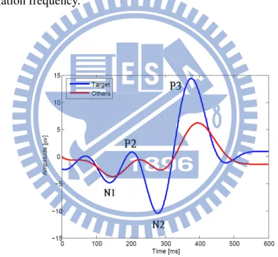
Figure 1.3: The P300 wave. The P300 (P3) is a positive deflection in the EEG, which appears approximately 300 ms after presentation of a rare or suprising stimulus. A series of negative and positive components (N1, P2, N2) procede the P3. While the P3 reflect high-level processing of stimuli, the earlier components reflect low-high-level, automatic processing of stimulus.
The P300 is a positive deflection in the EEG, appearing approximately 300 ms after the presentation of rare or surprising (Figure 1.3), task-relevant stimulus. [10, 20] It is one
of the endogenous ERPs are the result of later, more conscious processing of stimulus and have characteristics that depend mainly on the stimulus context. Specifically, subjecs should pay attention to the stimulus that presented in experiment. Many different stimulus modalities can be used to evoked the P300, such as visual, auditory, tactile, gustatory or olfactory. The P300 is a common research topic because it can be reliably measured and because the characteristics of the P300 waveform. For instance the latancy and amplitude can be influenced by various factors. Some important factors influencing the P300 are listed below.
• Target probability
The amplitude of P300 is inversely related to the probability of the stimulus. High amplitude of P300 are elicited while the probability of the target stimulus is low. In practice, the target stimulus usually presented around 10% probability to elicited a stable P300 response [18].
• Interstimulus interval
In recent study, the interstimulus interval (ISI) are positively related tothe P300 peak amplitude. The longer the ISI be used, the larger the P300 amplitude are presented. • Attention
The amplitude of the P300 depand on how the subjects focus on the stimuluse. In an oddball paradigm, the P300 can’t be elicited while the subjcets don’t concentrate on the target stimulus.
• Task Difficulty
The difficult task in the P300 experiment lead to the latency increases and amplitude decreases. For instance the P300 amplitude decreases while it is difficult to discrim-inate the target and non-target stimulus [8].
Two typical paradigms are used in P300 experiments, oddball paradigm and three stim-ulus paradigm. In the first paradigm, two different stimstim-ulus are used, target stimstim-ulus and non-target stimulus. The target stimlus are presnted rarely and the non-target stimulus are
presented frequently in a random successive order. Subjects are asked to focus on the tar-get stimulus. In three-stimulus paradigm, a novelty stimulus or a distracter stimulus are used besides target and non-target stimulus. This paradigm is modified from the oddball paradigm. The different type of P300 so-called P3a are elicited by the distracter stimu-lus that differ from P300 are elicited by oddball pradigm. The P3a could be elicited even though subjecs completely ignore the distractor stimulus. Nevertheless, the P300 so-called P3b are mostly used in BCI system.
1.5
Thesis Overview
Chapter 2 provides the overview of BCI systems, including the basic components and key-issues. We also introduce some present-day BCIs and some P300-based BCIs. The methods used in our BCI will be introduced in Chapter 3. Chapter 4 provides the experi-ment steup and detail of the online system we designed, and we show the analysis results of the offline experiment and onilne testing. In Chapter 5, we give some brief discussion. In Chapter 6 we give this thesis some conclusion.
Chapter 2
In this chapter we will give an overview to BCI systems. We first introduce some categories of BCI systems, then we briefly introduce some present-day BCIs and some P300-based BCIs. Next we list and explain some basic components and nowaday key-issues in a BCI system. In the end of this chapter we provide the thesis scope.
2.1
Categories of Brain-computer interface systems
Invasive and non-invasive systems
We have mentioned th non-invasive brain monitor techinques in previous cheapter. The BCI systems based on these techniques are non-invasive BCI systems and among these techniques, EEG is the most suitable for a BCI system. The ”non-invasive” means we don’t hav to directly record the brain activity by putting the electrodes into the brain, in which the user will be at medical risks. Therefore, the non-invasive BCIis less debatable. The disadvantages of the non-invasive BCI is the influence of the volume conductor effect, thus the quality of electrodes containing other noise overlappoing the brain activity.
On the contrary, for the invasive BCI systems, we have to put the electrodes into a user’s skull to monitor the brain directly. This is the main drawback of invasive BCI systems. The other disadvantage of the invasive ones is that the quality of the signals decades over time. However, the signals in a invasive BCI is of higher signal-to-noise ratio.
Due to the medical risks, present-day almost all of the BCI systems are non-invasive.
Pattern-recognition-based and operant-conditioning-based systems
The pattern-recognition-based BCI is based on congitive mental tasks. This kind system are often predefined. Commonly used mental tasks in current BCI system include motor imagery, arithmetic, visual, spatial operations. And user will perform more tha once these mental tasks to train a classifier used to recoginze his wish. The operant-conditioning-based BCI is operant-conditioning-based on the self-regulation of the EEG response. In other words, we train a user to control the BCI systems by regulate his brain signals. The representative work is Wolpaw µ-rhythm BCI and SCP BCI [22].
Synchronous and asynchronous systems
In a synchronous BCI, the user is notified to perform a mental activity when a specific external cue is shown. That means this kind of system operates in a cue-based mode and has the information about the onset of the mental activity in advance. The analyses and classification of the brain signals in the system is limited to the predefined fixed time period. Besides, the system is active only during the predefined period as well. BCI systems based on evoked potentials and ERPs belong to this category, such as P300, SCP. Besides EPRs, the BCI developed in Graz that analyzed the spontaneous EEG are also synchronous BCIs. The BCI that a user can intend a mental activity whenever he wishes to perform such mental activity is an asynchronous BCI. In the asynchronous BCI, the brain signals are an-alyzed and classified continuously. We have to not only classify from the redefined mental tasks but also discriminate events from noise and nonevents such as resting or idling states. Such a BCI system is more flexible and attractive to be utilized in practice. Besides the above advantages, it also offer a rapider response time than synchronous ones. However, the classification in an asynchronous BCI system is not accurate enough today.
2.2
Basic components in BCIs
Signal pre-processing
The goal of the stage is to enhance the signal-to-noise ratio. Typical procedures include amplification, filtering, possible artifact removal. For the filtering, the bandpass filtering is usually applied. In addition, a notch filter is also used to suppress the 60 Hz power line interference. As for the artifact removal, almost all BCIs rule out the signals if the EOG or EMG is detected to be used or over a predefined threshold.
Feature extraction
In this stage, certain features are extracted from the preprocessed signals. ERP, ERD/ERS and brain rhythms are typically used features in a BCI system. Besides the above fea-tures, various feature extraction methods have been studied to extract more discriminative
features, such as discrete wavelet transform, continuous wavelet transform, autoregress model(AR) or adaptive autoregress (AAR) model, power spectrum. All the above methods can be found in BCI competition 2003 papers.
Classification
The features extracted from feature extraction are fed to train a classifier. Many clas-sification methods have been proposed in pattern recognition field. The classifier in a BCI can be anything from a simple linear model to a complex nonlinear or a machine learning models. In general, the BCI has two phases training phase and testing phase. The training phase consists of a repetitive process of cue-based mental tasks to train a classifier. In the testing phase, we use the classifier built in the training phase to recognize different mental tasks.
Command translation
The goal of this step is to translate the classification output in previous step to an op-erator command. The command can be, e.g. a letter in a spelling system, choice of multi-choice system, a movement of a course on the user’s screen or nothing to be performed when the classification is ”resting” or ”idle”. The design of translation algorithm and de-vice control depends on what applications the BCI want to provide with.
Biofeedback
A feedback which make the user more easily adaptive to the system is a very important component for a BCI system. A feedback can indicate how well the asked mental activity was recognized by the system. When the system gives the feedback to a user, he will create a biofeedback which is the process that the user receives information about his biological state.
By Biofeedback, the user can monitor his physiological states, shape his brain electrical behavior, and voluntary modification of his EEG response. Today, nearly all BCI systems provide a feedback to users.
2.3
Present-day BCI systems
Here we introduce some present-day BCI systems, we mainly introduce two kinds of BCI systems, the ERP-based BCI and the motor-imagery based BCI.
2.3.1
ERP-based BCI
The event-related potential(ERP) is evoked by the external events, so this kind of BCI usually depends on the gaze of the user. We can always detect the ERP as long as we have enough trials. This kind of BCI has its advantages like the short training time and high accuracy. The drawbacks are the transition rate may be slow and the users may habituate to the system and lower the performance. Here we introduce three main ERP-based BCI, the P300-based, SSVEP-based BCI and SCP-based BCI.
P300-based BCI
The basic idea underlying P300-based BCI system is to use an similar oddball paradigm. Subjects decide which stimulus plays the role of the target stimulus. As the P300 occurs only if subjects voluntarily response to a specific stimulus, the specific stimulus chosen by the user can be automatically inferred from the EEG recorded during stimulus presen-tation. More specifically, the typical procedure in a P300-based BCI is as follows. First, the user decides a command which he wants to execute by the help of the BCI. Then, the stimulus are presented in the screen and the user focus on the selected stimulus. Finally, the recorded data is analyzed to infer which stimulus was chosen by the subject. This kind of BCI system had the advantage that needed a short training time and requiring no initial user training. The variant application of P300-based BCI are describe in Section 2.4
SSVEP-based BCI
The SSVEP is Steady-state Visual Evoked Potential. It is a response to a visual stimulus with a specific high frequency. The EEG signal power will increase at the specific stimulus frequency. Therefore with some different frequency stimulus on the screen we can detect which one has the user’s gaze. There are lots of BCI application using SSVEP, such as
Pfurtscheller [11], his team deveoped a application to control an electricla proschesis using SSVEP.
SCP-based BCI
This BCI is also called thought translation device (TTD) proposed at the University of Tbingen in Germany. TTD is an operant conditioning based BCI. The user is trained to control the BCI system for a long time by means of self-regulating his SCP. In the system, the user faces a screen and choose to move the cursor to the top or the bottom on the screen by controlling his amplitude of SCP. [2] The system will have a well performance if a user is completely trained. However, the drawback that hase to take a long time to train a user to fulfill self-regulation.
2.3.2
Motor-imagery based BCI
This kind of BCI basically no need to depend on the user’s gaze. The motor-imagery is a spontaneously induced EEG signal. Therefore this kind of BCI is more difficult to develop since the imagery and the concentration of each user may be different. One of the most successful BCI using motor-imagery tasks is Graz BCI is proposed by Gert Pfurtscheller. [12, 13] The development is mostly based on the detection of the ERD and ERS pattern in a motor-imagery task. Actually the concept of ERD and ERS was proposed by Pfurtscheller. In their works there are lots of research about different movement that causes different kind of ERD and ERS. They intend to left/right hand movement imagery, foot movement imagery, or tongue movement imagery. They use spatial filter as Common Spatial Pattern (CSP) or morlet wavelet transforms to extract the features. This kind of BCI has its advantages like high transition rate, and users may improve the performance through constant training. The drawbacks are, the training time is longer than a ERP-based BCI, and the user’s concentration is very improtant.
DONCHIN et al.: THE MENTAL PROSTHESIS: ASSESSING THE SPEED OF A P300-BASED BCI 175
Fig. 1. The stimulus matrix monitored by the subject. Every 125 ms one of the rows, or one of the columns of the matrix was intensified.
II. METHODS
A. Subjects
Ten able-bodied (six female) and four disabled subjects (wheelchair-bound; three with complete paraplegia, one incomplete paraplegia; two female) from the university com-munity participated in the experiment.
B. Stimuli and Procedure
The subjects viewed a display of the matrix exhibited in Fig. 1. The characters were presented as white characters on a black background, using a moderate and easily visible intensity. The matrix used in the present study differed in a number of minor details from the display used by Farwell and Donchin. Intensifying, in a random sequence, each of the 6 rows and 6 columns of the matrix produced an oddball sequence. Each intensification lasted 100 ms, with an SOA of 125 ms. The interval between trials (6 row and 6 column intensifications) was 1500 ms.
The subjects sat 50 cm from the display and were instructed to observe the display and to count the number of times the row, or the column, containing the designated target letter “P” was intensified. Thus, Prob(Target) 2/12 or 0.167. The rows and the columns were intensified in a random sequence in such a manner that all 6 rows and 6 columns were intensified before any was repeated. A “trial” in the study is thus defined as the intensification of all 12 elements of the matrix. The total dura-tion of such a trial was 1500 ms. The specific implementadura-tion of the BCI, using two separate computers, one for data acquisition the other for controlling the display, forced an interval of 1000 ms between trials. In a BCI implemented as a special purpose device the intertrial interval could be made arbitrarily short, ex-cept for the time required shifting gaze between characters. Each subject performed blocks of 15 trials each.
1) Data Acquisition and Processing: The EEG was
recorded from tin electrodes in an electrode cap (Electro-Cap International) at the Fz, Cz, Pz, O1, O2, and right mastoid sites, referenced to the left mastoid. The data were referenced off-line to averaged mastoids. The EEG was amplified using Biologic amplifiers (0.01–100 Hz passband) and digitized at the rate of 200 Hz. Vertical and horizontal EOG artifacts were removed from the EEG by an eye-movement correction method [10].
The P300 detection method followed the procedure devel-oped by Farwell and Donchin. Single-trial EEG epochs were de-rived in association with each intensification, beginning 300 ms prior to the intensification and lasting for 1100 ms. Thus, each trial yielded 12 such epochs, each associated with a specific row and a specific column. The method assumes that the epochs as-sociated with the relevant column and the relevant row will con-tain a detectable P300, while the other epochs will not. The data submitted to the detection algorithms were obtained by aver-aging together each combination of row and column single-trial epochs. Thus, there were 6 rows by 6 columns 36 epochs for each trial.
As is generally the case for ERP components, it is virtually impossible to visualize, or to detect numerically, the presence of an ERP in the epoch following a single event. The ERP is substantially smaller than the ongoing EEG activity; hence de-tecting ERP’s requires a method that extracts the ERP signal from the EEG “noise.” While averaging over all the trials ob-tained in a given study provides a very clear picture of the pat-tern of the ERP’s, it cannot be relied on for the purposes of com-munication at a relatively acceptable speed. Hence, while we will examine the grand-average ERP’s to obtain a clear view of the pattern of the signal we seek, much of the effort of devel-oping the BCI consists of determining the smallest number of trials that must be averaged to insure reliable detection.
III. RESULTS
1) Grand Average ERP’s: The epochs associated with the
target and nontarget stimuli were averaged over all trials used with each of the subjects, for each of the electrode sites used in the study. These data, averaged over the subjects, are presented in Fig. 2. It is quite evident that the rare “targets” elicit a large P300 whose scalp distribution is that used to define the P300, with the largest amplitude elicited at centro-parietal electrode sites. Thus, ERP’s for “Target Letter” were associated with the cell at the intersection of the correct row and correct column. The ERP’s for “Target Row/Column” were associated with the cells at the intersection of the correct row or column and an in-correct column or row, respectively. The ERP’s for “Standards” were associated with the cells at the intersection of incorrect rows and columns.
It is evident that a communication system relying on an av-erage of 40 trials can achieve perfect accuracy. That is, target rows and columns definitely elicit a large P300 that, given 40 trials, can be easily detected. As such an average requires a total of 60 s to communicate each character (1.5 s per trial for 40 trials 60 s) the system, while perfectly reliable, is unac-ceptably slow. There is, of course, a direct relationship between (a) Speller
114 IEEE TRANSACTIONS ON NEURAL SYSTEMS AND REHABILITATION ENGINEERING, VOL. 11, NO. 2, JUNE 2003
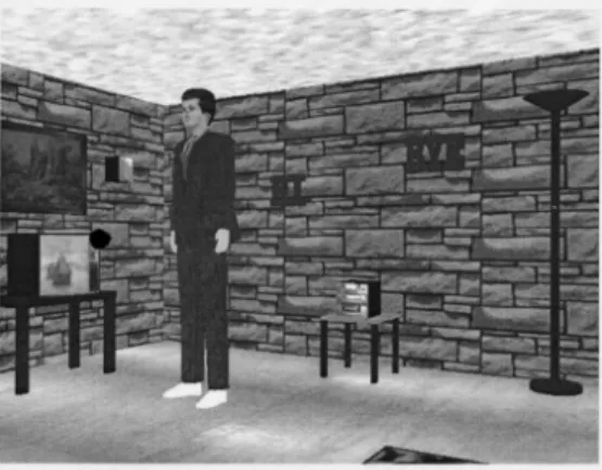
Fig. 1. Sample scene from the virtual apartment. The television, stereo, HI sign, BYE sign, and lamp are all controllable items. In this scene, a red sphere on the television set is blinking.
We conducted experiments to analyze the robustness of the P3 signal over virtual and nonvirtual environments. The goal was to determine if there were performance or qualitative experience differences between them. Subjects were asked to control several objects or commands in an online, single-trial classification experiment in a virtual apartment. Results indicate that there was no significant difference in signal or performance between use of VR and a computer monitor and that there was a performance difference between use of a fixed head view of the apartment versus freely viewing use of a computer monitor. The results and possible ramifications are discussed in the following.
II. EXPERIMENTALSETUP
We established five objects or commands that could be controlled by the user in the virtual apartment, as shown in Fig. 1—a lamp, a stereo system, a television set, a Hi command, and a Bye command. The lamp, stereo, and television all worked as toggle switches to turn the items on/off. The Hi and Bye commands would make a 3-D graphics figure appear (for Hi) or disappear (for Bye). These commands were chosen to show that commands could control simple objects such as lights as well as more complex operations like the control of the graphical figure. All responses to commands were visual—for instance, musical notes appeared over the stereo when the stereo was on and a picture appeared in the television screen when it was on.
A sphere associated with each controllable object or command was normally invisible (not drawn in the environment); when visible, it had a semitransparent red coloring. Semitransparency was done so that blinking spheres (see the following) would be less distracting to sub-jects concentrating on one specific sphere for the task. The size of the sphere in reference to the controllable item sizes may be seen in Fig. 1. Approximately once per second, a stimulus was provided when the sphere on a randomly chosen item appeared. The stimulus would last for approximately 250 ms. The stimulus presentation rate varied by up to 16 ms in a random manner. The P3 response occurs for task-rele-vant stimuli. To make the red sphere flashes on the controllable object task-relevant, subjects had to count the flashes on a particular item and not count the flashes on the other (not task-relevant) objects.
Two experimental environments were set up: one VR and one non-VR. The experimental setups for the VR and non-VR environ-ments were almost identical. The main difference was that all graphics for the non-VR environment were rendered on a 21-in Silicon Graphics
monitor, whereas the VR environment conditions were displayed in a head-mounted display (HMD). An onyx silicon graphics machine with an infinite reality graphics engine rendered the VR interface and all subjects sat in a chair to view the apartment environment.
Seven electrode sites were arranged on the heads of nine subjects with a linked mastoid reference. Sites FZ, CZ, PZ, P3, P4, as well as an upper and lower vertical electrooculographic (EOG) channel were used from the international 10–20 system of placement [9]. The EEG signal was amplified using Grass amplifiers with an analog bandwidth from 0.1 to 100 Hz. Electrode impedances were between 2–10 k for all subjects. Signals were then digitized at a rate of 512 Hz and stored to a computer. A numerical code for the particular sphere flash was then sent to the BCI over a serial port. An epoch size from0100 ms (prior to stimulus onset) to 1500 ms was specified for a total epoch size of 1600 ms. The data were recorded continuously and saved to a file.
Our experiment was designed to address the following questions. 1) Are there significant differences between the evoked potentials
obtained in VR and those obtained while watching a computer monitor?
2) Are there significant performance differences for trials obtained in VR as opposed to watching a computer monitor? 3) Are there performance differences over time?
4) Are there qualitative subject experience differences between the different conditions?
The answer to the first question could change the significance of results reported dealing with VR if the signals were different due to the environment. Performance differences could make VR a better or worse environment for BCI training. The last two questions were of interest since they could reflect learning due to online control and feedback as well as possible motivational reasons for using VR.
III. EXPERIMENT
The experiment consisted of four tasks.
1) Calibration: the subject counted the number of sphere flashes located on the virtual lamp on a monitor.
2) VR condition: the subject was fully immersed in the virtual apart-ment while wearing a HMD.
3) Monitor condition: the subject looked at the virtual apartment on a monitor.
4) Fixed-display condition: the subject looked at the virtual apart-ment on a fixed screen inside of the HMD. This represented a condition between truly immersive VR and watching a computer monitor, since it took place inside of the HMD, but had a fixed screen like a computer monitor.
The calibration task was used to train a signal processing algorithm on a particular subject’s P3 response. A total of 300 stimulus presen-tations were presented to the subject. In this task, subjects were told to count only the lamp sphere flashes; thus, in this task, only the lamp sphere flashes were task-relevant and these flashes should have caused a P3 response. Since the spheres flashed randomly over the five con-trollable items, 606 5 lamp flashes occurred over the course of 5 min. It can be seen from the grand average in Fig. 2 that the lamp sphere caused a P3 response, whereas the flashes on other items did not.
For online recognition and analysis, EOG artifacts were regressed out of the signals of interest using the algorithm by Semlitsch [11]. The signal recognition algorithms used for classification are described in [12]. While the experiment involved online classification and feed-back, an offline analysis was done to compare the obtained P3 signals between different conditions. Only epochs with a maximum vertical EOG signal of less than 50 uV were used. This eliminated the possi-bility of EOG contamination of the averages to be compared.
Authorized licensed use limited to: National Chiao Tung University. Downloaded on May 20, 2009 at 09:28 from IEEE Xplore. Restrictions apply.
(b) Virtual aparment
Figure 2.1: (a)An typical 6 x 6 P300-based Speller [5, 7] (b)Controling objects in virtual apartment base on P300 [1]
2.4
Review of P300-based BCI systems
P300 speller
The fisrt P300-based BCI has been presented by Farwell and Donchin in 1988. [5, 7] In this system, users are gazing at a 6x6 matrix on the screen.(Figure 2.1 (a)) In the matrix there are letters, numbers, and symbols. When the system starts, it flashes each row and column in the matrix with random sequence. The user is asked to focus his attention on the symbol he wants to select and count the number of time that this symbol is flashed. To infer which symbol the subject wanted to select, it was thus sufficient to find out which flashes evoked a P300. The principle of this system based on the less probability of the target symbol. The probability of each symbol are 1/6. The low probability led to evoke the P300 response.
Since the work of Farwell and Donchin several researchers have proposed extensions and modification of the basic P300 speller paradigm. Otherwise, many other studies were concerned with classification algorithms for the P300 speller.
Virtual apartment
A departure from the P300 spellerparadigm was initiated by Bayliss who tested if the P300 could be evoked in a virtual reality environment [1]. In the system, subjects viewed a virtual apartment as Figure 2.1(b) that alternatively on a monitor or through a head-mounted display. Subjects control five items in the virtual apartment, for instance switching on/off the television or stereo. The system work by concentrating on small spheres that were flashing in randm order over thecontrollable items. They reveal the small variance of P300 reponse between monitor and head-mounted display conditions. It was shown that virtual controllable experimental environments is an interesting alternative to implement a P300 paradigm.
and finally, the generation of feedback concerning the movement of the ball (seeFig. 1). The interval between the presentation of two arrows (inter-trial interval: ITI) was fixed to 2.5 s in order to achieve optimal on-line data processing. A session was defined as the sequence of trials sufficient to permit the reaching of the goal-point (rangeZ 5–90 trials).
(seeFig. 1c), the ball moved on the graphical interface according to the direction of the flashed arrow (seeFig. 1d). If the P300 was not detected then the ball remained still.
Each participant performed three learning sessions in the first day and 12 testing sessions (TS) spread over the following 11 days (i.e. second day: 3 TS/two-day-interval/fifth day: 3 TS/two-day-interval/eighth day: 3 TS/two-day-interval/eleventh day: 3 TS). 2.3. P300 acquisition
We used a standard procedure for recording ERPs (Heinze et al., 1999; Picton et al., 2000). Cup silver-chloride electrodes were placed according to the inter-national 10–20 system at Fz, Cz, Pz and Oz. All four electrodes were referenced to bilateral (joined) earlobes. The EOG was recorded from two electrodes, the first placed below the right eye and the second located 2 cm laterally to, and above, the outer canthus. The four EEG channels and the single EOG channel were amplified by SynAmps (NeuroSoft, Inc.), band-pass filtered between 0.15 and 30 Hz, and digitized (with a 16-bit resolution) at a 200 Hz sampling rate. Each recorded single-sweep epoch synchronized with the stimulus began 500 ms before stimulus onset, and lasted until 1000 ms after the stimulus trigger signal, for a total length of 1500 ms. Thus, 300 sampled points per channel were available after each stimulus to detect the presence or absence of the P300 wave. These data (a matrix of 300!5) were processed on-line through the following three-step-sequence.
2.4. P300 analysis
1. Independent components analysis (ICA) decomposition
ICA decomposition makes it possible to split up acquired raw signals into statistically independent source signals, on the basis of definite mathematics hypotheses (Cover and Thomas, 1991; Jung et al., 1998). More precisely, it is hypothesized that one of the source signals reflects the ERP. An automatic selection of this source, using a fuzzy method (Beverina et al., 2004), allowed us to use ICA decomposition during on-line testing sessions, aimed to select the P300 wave among other components such as the EOG signal.
The procedure for ICA decomposition is illustrated in
Fig. 2: ICA determines the components of the raw signal (i.e. spatially fixed and temporally independent sources; see
Fig. 2b). These components represent the observed time-varying responses (Fig. 2a), without directly specify their position in the brain. ICA uses statistical moments of high order to find the mixing matrix for these source, which creates the signals actually observed. One of these sources reflects the ERP’s characteristics (seeFig. 2c). The
ERP-Fig. 1. Representation of a trial. (a) The virtual object (blue ball in the starting-point), the required path (hatched-line, not visualized during the experiment), and the goal-point (red cross); (b) yellow flashed arrow (i.e. target) indicating the required direction of the movement of the ball towards the goal-point; (c) the P300 is elicited by the target stimulus and is recognised by the system; (d) movement of the ball following P300 recognition.
F. Piccione et al. / Clinical Neurophysiology 117 (2006) 531–537 533
(a) Curser control
Proceedingsofthe 2007 IEEE 10th InternationalConferenceon Rehabilitation Robotics, June 12-15, Noordwijk, The Netherlands
Controlling a wheelchair using aBCI with low information transfer rate
Brice Rebsamen1, Etienne Burdet2'1, Cuntai Guan3, Chee LeongTeol,Qiang Zeng1, Marcelo Ang1 and Christian Laugier4 1: Departmentof Mechanical Engineering, National University of Singapore
2: Departmentof Bioengineering, Imperial College London, UK 3: Institute for Infocomm Research, A*STAR, Singapore
4: INRIARhone-Alpes, France
{brice,zengqiang,mpeteocl,mpeangh} @nus.edu.sg, e.burdet@ imperial.ac.uk, [email protected], christian.laugier@ inrialpes.fr
Abstract-This paper describes a control hierarchy to drive
awheelchairusing an interface with asynchronous and very low information transfer rate signal. Path guiding assistance allows the user tobringhis or her wheelchair in abuilding
environment,from one destination to the next destination. The
user canstopthewheelchairvoluntarily duringmovement, or through a reflex elicited by sensors. Decisions aresimplifiedby presenting only the possible selections on the GUI, in a context dependent menu. This system isimplementedon aconventional wheelchair with a P300 Brain Machine Interface. Tests with healthysubjects show that this system can move the wheelchair in atypical building environment according to the wishes of its user, and that the brain control is not disturbed by the movement.
I. INTRODUCTION
Alternative Input Devices (AID) available on the market canhelp physically challenged peopletocontrol computers,
communication devices or a wheelchair. This includes a
simple stickheld between theteeth,buttons andjoysticks
of various sizes that can be activatedby various parts of
thebody,gazetracking systems orhead movement based
systems toenable control of a cursor on a screen, or even
relatively newBrain Computer Interfaces (BCI) for direct
control of a computerby thought.
While there exists a great number of AID, in many
cases controlling a device still remains a challenge. For
instance, a person with poor motor control andlargetremor
will haveproblemsto actuate even asystemwith asingle
switch,as weexperiencedrecently[1].As a consequence the
delaybetweenclicks may amount to severalseconds,and it is impossibleto producea command atregularintervals.
Further, the button may be pressedinvoluntarily.
Communication iseven moredifficult for locked inpeople
such as individuals suffering from Amyotrophic Lateral
Sclerosis,adegenerativedisease of themotor neuronwhich,
inthe advanced stage, leads tocomplete paralysisof every
single muscle in the body. These persons cannot use a
conventionalAID,but may be able tocommunicate with
other people and devices using a BCI. For instance, an
electroencephalograph (EEG)BCIuses theelectric signal
measured on thescalptodetectvoluntarycommands.
How-ever,theEEGsignalis verynoisyand hasalarge variability.
Therefore, either theuncertainty onthe command will be
Fig. 1. Photograph of the prototype wheelchair controlled by thought, which can move in abuildingenvironment.
high, or the time between consecutive commands will be
long,inthe order of seconds.
Can such a poorsignalbe used tosafelyandefficiently
control a wheelchair thatrequires areal-timespecification
of itspositionwithin the threedimensional space ofplanar
motion? This is the challenge we address in this paper.
We examine how to control a wheelchair usinga signal
which is asynchronousand has an ultra-low information
transferrate.Wepropose a robust control strategy, which
we then test on a Brain Controlled Wheelchair (BCW) (Fig. 1).Thisapplicationischallenging,as,inaddition to the
multidimensionalworkspace,the user has tocontrolsafety.
Safetyiseven moreimportantforawheelchairuser asfora
healthy driver,who is moresubjectto severeinjuriesbecause
he or she cannot reactappropriatelyto anaccident.
A solution to use an infrequent signal for controlling
1-4244-1320-6/07/$25.00(c)2007IEEE 1003
(b) Brain-controlled wheelchair
Proceedingsof the 2007 IEEE 10th International Conference on Rehabilitation Robotics, June 12-15, Noordwijk, The Netherlands
awheelchairconsists in endowing the system with some
autonomy,such that the useronlyneeds to providesimple
directives from time to time. Aconventional approachtoward
autonomyis to equip thevehiclewith sensors to perform
obstacledetection andlocalization.The robot has to be given
sufficientartificialintelligencetogenerate asuitable
trajec-tory tothe destination. However this strategy has aheavycost
(bothfinancialandcomputational)and the decision takenby
the systemmightseemawkward to a human observer[2].
Hence autonomousvehicleshave been observed to refuse to
moveforward due to someobstacles, whileahuman driver
wouldeasilybeableto moveits waythrough [3].
Forallthese reasons, we decided todevelopamotion
controlstrategybased on humansupervisionrather than
on sensorbasedreasoning.Weconstrain the movement to
guidepaths joining locationsof interest in the environment.
These paths, defined by the user or ahelper,arestored in
the computer memoryformingageometric graphof the
environment. Thewheelchairuser canthenselectadesired
destinationusinga contextdependentmenushowinghim or
her the currentpossibilities,and a pathfollowing controller
automaticalydrives thewheelchairalongtheappropriate
path.
This paper presents the robustcontrolstrategy we
pro-poseforvehicles controlledwith anasynchronousandlow
information rate commandsignal (SectionII).Itdescribes the
workingprototypeof the braincontrolled wheelchair(BCW)
wehavedeveloped [4],which uses thiscontrolstrategyand
aP300BCI,aswellasexperimentsweperformedto test
this roboticwheelchairinrealconditions(Section IV).
BCI have so far been used at staticpositions[5]-[11],and
it is not obvious thattheyworksatisfactorilywhen the user
ismovinginthe environment. However for ourwheelchair
weneed reactions of the userduringmovement.Wehave
thusdevelopedanalgorithm enablingintervention of the
userduringmovement,which ispresentedinSection III
describingthe P300 BCI. Wealsoperformed experimentsto
investigatewhether thecontrolis affectedbythe movement,
which arealsodescribed in Section IV.
II.ROBUST AND SAFE MOTION CONTROL STRATEGY
A. Motionguidance provides drivingassistance
Inorder to adress thecontradictorycontraints oflow
information transfer ratesignaland the wish of the user
tocontrol the wheelchairmovement, weneedasimple and
robustcontrolstrategy. We propose to representthe
envi-ronmentbyageometric graphofguiding paths connecting
locationsof interests.Fig.2shows such a map for atypical
home environment. Thissimplemapof the environment
canbebuiltupautomaticallyif aplanof thebuilding
isavailable. Alternatively,it can be formedusing walk
throughprogramming,i.e. the on-boardcomputerrecords the
trajectory whileahelperispushingthewheelchairbetween
twolocationsand aleast-squarefit with aB-splinesis used
asguiding pathforsubsequentmovements.
Usingaguiding pathmap, navigatingwith thewheelchair
becomesfairly simple.The GUI prompts the user with the
Fig. 2. Example of a mapwith guiding path in a home environment.The paths are defined by a small number of control points which have a clear geometric meaning as attraction points of a B-splines, and can be used to modify the path. For example the figure shows how the path in the kitchen ismodified to avoid a large object which makes obstacle.
Fig. 3. Contextdependent menu for selection of the next move. When the wheelchair reaches adestination, the commands displayed to thesubject areupdated to the new destination. Note that the number of commands is notlimited to nine. Inparticular,forthe P300 BCI the number ofpossible commanddisplayed on the GUI amounts about 30.
destinations connected to the currentlocation.Therefore the
menupresentedonthe GUI is contextdependent,which
reduces theselectionto afewpossibilitiesand thus reduces
thecomplexityof theselectionprocess.Upon selection
of adestination,thepath controller [12], [13]movesthe
wheelchairalong the pathtoits end.
Thewheelchairuser or ahelpercaneasily modifythe
guiding pathstoadapttomodificationsintheenvironment
such aschangesinthe furniturelocations orobstacles.
Simpleand efficienttoolsforpath editingaredescribed
in[14].Itisalsovery easy toextend the mapby adding
newpathsandnodes,orconnectingtwomapstogether,for
instance at alift.
B.Localisation
Using guiding paths,oursystemdoes notrequiretomodel
theenvironment,thus it does not needcomplexsensor
or sensorprocessing. However,successfully negotiatinga
1-4244-1320-6/07/$25.00 (c)2007IEEE 1004
Proceedingsof the 2007 IEEE 10th International Conference on Rehabilitation Robotics, June 12-15, Noordwijk, The Netherlands
awheelchairconsists in endowing the system with some
autonomy,such that the useronlyneeds to providesimple
directives from time to time. Aconventional approachtoward
autonomyis to equip thevehiclewith sensors to perform
obstacledetection andlocalization.The robot has to be given
sufficientartificialintelligencetogenerate asuitable
trajec-tory tothe destination. However this strategy has aheavycost
(bothfinancialandcomputational)and the decision takenby
the systemmightseemawkward to a human observer[2].
Hence autonomousvehicleshave been observed to refuse to
moveforward due to someobstacles, whileahuman driver
wouldeasilybeableto moveits waythrough [3].
Forallthese reasons, we decided todevelopamotion
controlstrategybased on humansupervisionrather than
on sensorbasedreasoning.Weconstrain the movement to
guidepaths joining locationsof interest in the environment.
These paths, defined by the user or ahelper,arestored in
the computer memoryformingageometric graphof the
environment. Thewheelchairuser canthenselectadesired
destinationusinga contextdependentmenushowinghim or
her the currentpossibilities,and a pathfollowing controller
automaticalydrives thewheelchairalongtheappropriate
path.
This paper presents the robustcontrolstrategy we
pro-poseforvehicles controlledwith anasynchronousandlow
information rate commandsignal (SectionII).Itdescribes the
workingprototypeof the braincontrolled wheelchair(BCW)
wehavedeveloped [4],which uses thiscontrolstrategyand
aP300BCI,aswellasexperimentsweperformedto test
this roboticwheelchairinrealconditions(Section IV).
BCI have so far been used at staticpositions[5]-[11],and
it is not obvious thattheyworksatisfactorilywhen the user
ismovinginthe environment. However for ourwheelchair
weneed reactions of the userduringmovement.Wehave
thusdevelopedanalgorithm enablingintervention of the
userduringmovement,which ispresentedinSection III
describingthe P300 BCI. Wealsoperformed experimentsto
investigatewhether thecontrolis affectedbythe movement,
which arealsodescribed in Section IV.
II.ROBUST AND SAFE MOTION CONTROL STRATEGY
A. Motionguidance provides drivingassistance
Inorder to adress thecontradictorycontraints oflow
information transfer ratesignaland the wish of the user
tocontrol the wheelchairmovement, weneedasimple and
robustcontrolstrategy. We propose to representthe
envi-ronmentbyageometric graphofguiding paths connecting
locationsof interests.Fig.2shows such a map for atypical
home environment. Thissimplemapof the environment
canbebuiltupautomaticallyif aplanof thebuilding
isavailable.Alternatively,it can be formedusing walk
throughprogramming,i.e. the on-boardcomputerrecords the
trajectory whileahelperispushingthewheelchairbetween
twolocationsand aleast-squarefit with aB-splinesis used
asguiding pathforsubsequentmovements.
Usingaguiding pathmap, navigatingwith thewheelchair
becomesfairly simple.The GUI prompts the user with the
Fig. 2. Example of a mapwith guiding path in a home environment.The paths are defined by a small number of control points which have a clear geometric meaning as attraction points of a B-splines, and can be used to modify the path. For example the figure shows how the path in the kitchen ismodified to avoid a large object which makes obstacle.
Fig. 3. Contextdependent menu for selection of the next move. When the wheelchair reaches adestination, the commands displayed to thesubject areupdated to the new destination. Note that the number of commands is notlimited to nine. Inparticular,forthe P300 BCI the number ofpossible commanddisplayed on the GUI amounts about 30.
destinations connected to the currentlocation.Therefore the
menupresentedonthe GUI is contextdependent,which
reduces theselectionto afewpossibilitiesand thus reduces
thecomplexityof theselectionprocess.Upon selection
of adestination,thepath controller [12], [13]movesthe
wheelchairalong the pathtoits end.
Thewheelchairuser or ahelpercaneasily modifythe
guiding pathstoadapttomodificationsintheenvironment
such aschangesinthe furniturelocationsorobstacles.
Simpleand efficienttoolsforpath editingaredescribed
in[14].Itisalsovery easy toextend the mapby adding
newpathsandnodes,orconnectingtwomapstogether,for
instance at alift.
B.Localisation
Using guiding paths,oursystemdoes notrequiretomodel
theenvironment,thus it does not needcomplexsensor
or sensorprocessing. However,successfully negotiatinga
1-4244-1320-6/07/$25.00 (c)2007IEEE 1004
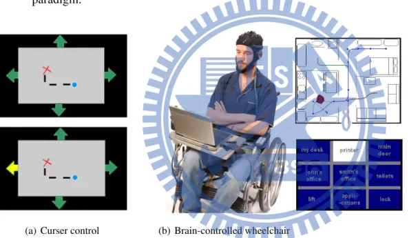
Figure 2.2: (a) Controling the curser by gazing on each arrows. [14] (b)Controling the wheelchair to nine places in the building. [15]
Cursor control
One system allow subjects to contorl a two-dimensional cursor with the help of P300 was presented by Piccione. [14]. In this paradigm, Visual stimuli consisting of four arrows (up, right, down,left) were randomly presented in peripheral positions on the screen.(Figure
2.4(a)) Participants hade to pay attention to the arrow indicating the correct direction for a ball to move. They proposed the system that had the well performance for healthy subjects but not suitable for locked-in sndrome patients.
Brain-controlled wheelchair
Another P300 BCI paradigm was presented by Rebsamen. [15]. The system presented a 3 x 3 matrix consist nine place choices in a building.(Figure 2.4(b)) This paradigm is similar to the P300 speller for reduce the matrix. It is implemented on a conventional wheelchair with embedded system. That is the first application of P300-based BCI for controlling a realistic object.
Four-choice BCI
A initial study of using P300-based BCI for disabled subjects that presented by Sellers and Donchin [16]. Four smtimulus (YES, NO, END, PASS) with successive order pre-sented randomly on the screen. The purpose of this paradigm was to simplify the system for disabled subjects who might have visual deficits. Because it is hardly to concentrate on a small item on a screen for disable subjects, and they also can’t do too much eye move-ments. In this study, two different stimulus are tested, auditory and combinations of visual and auditory. The results show the system based on visual and combinations of visual and auditory stimulus had better performance than only using auditory. Futhermore they proved that communicating with external world by P300-based BCI was possible for the disabled subjets.
2.5
Limitations
Although the BCI systems we introduced above looks well, there are still some lim-itations in present-day BCI systems. Here we list some normal difficulties when doing researches on BCI systems.
Habituation
In a ERP-based BCI, we use the evoked potential from the subejcts to develop a BCI system. For the evoked potential is not controlled by our own will, we may get used to the BCI system and that affects the performance [4].
Noise
As we mentioned before, the EEG signal is poor on the Signal-to-noise ratio. The artifact noise is always a big problem in analysing EEG signals. Eye blinking, eye move-ments, the heart beating, any possible single small movement causes artifact noises to the EEG signal. Furthermore, not only an artifact causes noises. The interference from the environment, the power line, or the devices, they are also contaminating the EEG signal. In a BCI system, we detect the spontaneous EEG signals or the evoked potential. Both are very small changes and can be easily affected by these noises. In addition to the artifacts and interference, a distraction of the user also causes noises to the EEG signal. As a hu-man being is very complicated, every little cognitive task has its own response on the EEG signal. We can’t be sure that every user of the BCI system are always concentrating to the system, one may easily lose concentration and that reduces the performance of a BCI.
Fatigue
Another limitation to BCI systems is the fatigue of the users. As we introduced in the previous section, the ERP-based BCI keeps giving stimulus to the users and detect their responses. These stimuli may be some quickly changed pictures or flashing, and these fatigue a user easily. Even if in a motor-imagery based BCI, the users may get tired easily because of the continuous concentrate on the imagenery.
2.6
Key-issues in BCI systems
Here we list some key-issues in BCI systems. The future researches on BCI systems may be mostly about these difficult issues.
Noise Reduction
As we mentioned in the previous section, the noise is a limitation to the EEG analyses and BCI systems. How to reduce the noise and the non-interested signals is an issue. Today there are some practical methods to reduce the noises, such as EOG rejection, bandpass filtering, Independent component analysis (ICA), or Laplacian spatial filtering. In this thesis, we use EOG rejection, bandpass filtering and averaging to reduce the noise.
Features
How to find significant features from the EEG signal is an important issue. People have been trying with many methods to extract significant features from the raw EEG data. In this work, we use the SWDA to select significant features from time points.
Adaptation
There are two adaptation issues in a BCI system. The first is the users should adapt themselves to the system, that is, self-training of the users. The second is, the BCI system should adapt itselves to the users, that is a machine learning issue. Both adaptation issues are important, and these two issues work totally different. If we are trying to self-training a user, we should lower the variability of the BCI system, or the users may not be able to get himself trained well because the feedback keeps changing. If we want to make the system adapt itselves to the users, the system should have more flexibilty that adative for variant subjects with variant situation. In our study, we using a threshold to online adaptive to stoping. We will describe in Chapter 3.
Biofeedback
As we mentioned before, the biofeedback is a important component in the BCI sys-tem. Nearly all BCI systems need a biofeedback to the users. This issue is about how the biofeedback affects the users, and how to design useful biofeedback. The design of differ-ent biofeedback may result in differdiffer-ent mdiffer-ental work and stimulus, which influences on the signal. Is is helpful for subjects to adapt themself to improve the performance. However,