This article was downloaded by: [National Chiao Tung University 國立交通大學] On: 21 July 2015, At: 02:24
Publisher: Taylor & Francis
Informa Ltd Registered in England and Wales Registered Number: 1072954 Registered office: 5 Howick Place, London, SW1P 1WG
Click for updates
Molecular Crystals and Liquid Crystals
Publication details, including instructions for authors and subscription information:http://www.tandfonline.com/loi/gmcl20
Individually Adapted LC-lens Array for 3D
Applications
Yi-Pai Huanga, Tai-Hsieng Jena, Yu-Cheng Changa, Po-Yuan Shieha, Chi-Wei Chena & Lin-Yao Liaoa
a
Department of Photonics/Display Institute, National Chiao-Tung University, HsinChu, Taiwan
Published online: 15 Dec 2014.
To cite this article: Yi-Pai Huang, Tai-Hsieng Jen, Yu-Cheng Chang, Po-Yuan Shieh, Chi-Wei Chen & Lin-Yao Liao (2014) Individually Adapted LC-lens Array for 3D Applications, Molecular Crystals and Liquid Crystals, 605:1, 267-274, DOI: 10.1080/15421406.2014.917487
To link to this article: http://dx.doi.org/10.1080/15421406.2014.917487
PLEASE SCROLL DOWN FOR ARTICLE
Taylor & Francis makes every effort to ensure the accuracy of all the information (the “Content”) contained in the publications on our platform. However, Taylor & Francis, our agents, and our licensors make no representations or warranties whatsoever as to the accuracy, completeness, or suitability for any purpose of the Content. Any opinions and views expressed in this publication are the opinions and views of the authors, and are not the views of or endorsed by Taylor & Francis. The accuracy of the Content should not be relied upon and should be independently verified with primary sources of information. Taylor and Francis shall not be liable for any losses, actions, claims, proceedings, demands, costs, expenses, damages, and other liabilities whatsoever or howsoever caused arising directly or indirectly in connection with, in relation to or arising out of the use of the Content.
This article may be used for research, teaching, and private study purposes. Any substantial or systematic reproduction, redistribution, reselling, loan, sub-licensing, systematic supply, or distribution in any form to anyone is expressly forbidden. Terms &
Conditions of access and use can be found at http://www.tandfonline.com/page/terms-and-conditions
Mol. Cryst. Liq. Cryst., Vol. 605: pp. 267–274, 2014
Copyright©Taylor & Francis Group, LLC
ISSN: 1542-1406 print/1563-5287 online DOI: 10.1080/15421406.2014.917487
Individually Adapted LC-lens Array for 3D
Applications
YI-PAI HUANG, TAI-HSIENG JEN, YU-CHENG CHANG,
PO-YUAN SHIEH, CHI-WEI CHEN, AND LIN-YAO LIAO
Department of Photonics/Display Institute, National Chiao-Tung University, HsinChu, TaiwanA low driving voltage with fast response LC-lens was developed. By implementing the LC-lens as an array structure, it can be adaptively used for 2D/3D switching and 3D rotation on auto- stereoscopic display. Additionally, it also can be utilized as a depth sensor for 3D capturing.
Keywords Liquid crystal lens array; 3D display; 3D image capturing
1. Introduction
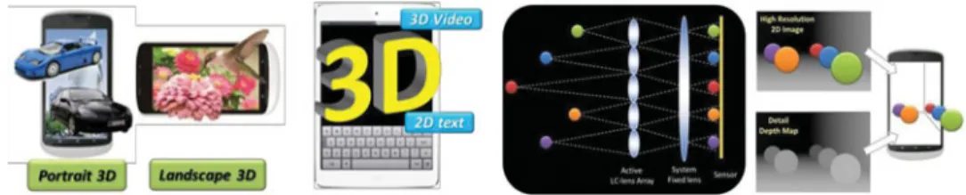
Recently, many types of 2D/3D switchable auto-stereoscopic displays are proposed in order to keep the 2D resolution [1-4]. The LC devices can perform the switchable parallax barrier and lenticular lens to enable 3D displays to switch between 2D and 3D modes. However, the 2D/3D switchable function is insufficient for current portable devices having auto screen rotate function, such as smart phones and tablet PCs, because the current 2D/3D switchable function is unable to achieve the 3D rotation due to disabling to change the arrangement direction of parallax barrier or lenticular lens. Additionally, those technologies cannot display full-resolution 2D contents and 3D contents at the same time, because these LC devices cannot locally perform parallax barrier or lenticular lens. The resolution of 2D contents will be reduced by at least half resolution depending on the number of views of the 3D display. Thus, we need an electrically switchable device having the 2D/3D switchable, dual-oriented 3D and partial 2D/3D switchable functions for current portable devices, as shown in Fig. 1.
For 3D Display, in this paper, we propose a multifunctional LC lens array that enabled auto-stereoscopic displays to achieve above three functions. Additionally, the design of LC lens devices is based on a compact size and easy-fabrication without any curved surface. Thus, the fabrication can be compatible with the fabrication of the current well-developed LCD industry and make auto-stereoscopic displays have more functions and applications used in our daily life.
This paper was originally submitted to Molecular Crystals and Liquid Crystals, Volume 594, Proceedings of Optics of Liquid Crystals 2013.
∗Address correspondence to Yi-Pai Huang, Rm. 516, CPT Building, 1001 TaShud Rd., HsinChu,
30010, Taiwan R.O.C. E-mail: [email protected]
Color versions of one or more of the figures in the article can be found online at www.tandfonline.com/gmcl.
267
268 Y.-P. Huang et al.
Figure 1. Schematic plot of adaptive LC-lens Array for (a) dual-oriented 3D and partial 2D/3D
switchable display and (b) High dynamic depth range(HDDR) 3D image capturing applications. Not only applying LC-lens array on 3D displays, it also can be implemented for 3D camera system. Light field camera [5-9] which adding a micro-lens array in front of the sensor can recode incident light directions by single shot frame. Unfortunately, it has low resolution issue and needs complex algorithm. Integral image system, in the other hand, can capture and reconstruct a directive 3D image through a micro-lens array without heavy calculation. However, it needs an all-in-focus plenoptic image to reconstruct a clear 3D image, which means the working range will be limited by the depth of field of camera main lens. Therefore, these methods are difficult to capture a clear 3D image in deep screen with both near and far objects, during the depth of field is narrow in near distance.
For 3D image capturing, in this paper, we proposed a depth information capturing system with high dynamic depth range (HDDR), which is inherited from the high dynamic range (HDR) camera. Unlike conventional extending depth of field (EDoF) method, the HDDR method doesn’t need applying optical units, and will not deteriorate the image quality. As show in Fig. 1, the active lens array will focus on different distance respectively. Each object in this screen will be clearly captured by at least three elemental lenses. Then we can estimate the distance of each object using the method depth from disparity. Finally, those depth map focused in different distance will be fused into one refined depth map.
2. Dual-Oriented 3D and Partial 2D/3D Switchable Display
A. Structure of Multi-functional LC Lens Array
The structure of a unit in the LC lens array consisted of an LC layer sandwiched between two resistive films, two kinds of arrangement directions of top and bottom electrodes, as shown in Fig. 2. The function of the resistive films is to divide the voltage gradually between the low and high electric potential and generate a gradient voltage distribution to form good lens effect. Additionally, the resistive film can make the stripe electrodes as a plane electrode to eliminate lens effect if applying a uniform voltage on those electrodes.
Figure 2. Sketch of the structure of multi-functional liquid crystal lens array, and driving method
for dual-oriented 3D switchable function.
3D LC-lens Array 269
Figure 3. Driving method of partial 2D/3D switchable function.
Therefore, this LC lens array can form uniform and gradient refractive index distributions locally.
B. Dual-oriented 3D Switchable Function
In order to achieve dual-oriented 3D switchable function, top electrodes and bottom elec-trodes must have different orientations, as shown in Fig. 3. When all bottom elecelec-trodes are connected to ground and top electrodes are driven by interlaced voltage, VD and ground, LC lens arrange in the horizontal orientation. Due to the same driving voltage, the bottom electrodes become a full electrode with ground voltage. When bottom electrodes are driven by interlaced voltage, LC lens switch to the vertical orientation.
C. Partial 2D/3D Switchable Function
The driving method partial 2D/3D switchable function is shown in Fig. 3. If we want to form the lens in the 3D region, there are no lenses in the other regions. This driving method needs three different voltages, V3D, V2D, TOPand V2D, BOT, which applied on the bottom electrodes in the 3D regions, the top and bottom electrodes in the 2D regions. The magnitude of V2D, TOPand V2D, BOTare higher than V3D. Therefore, there is a big potential difference between the top and bottom in the 2D regions. It make the whole LC are vertical.
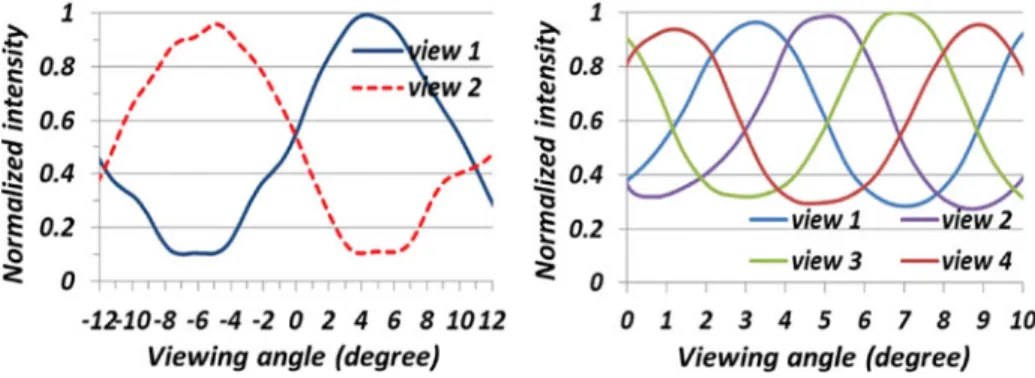
Figure 4. Angular distributions for horizontal and vertical 3D modes.
270 Y.-P. Huang et al.
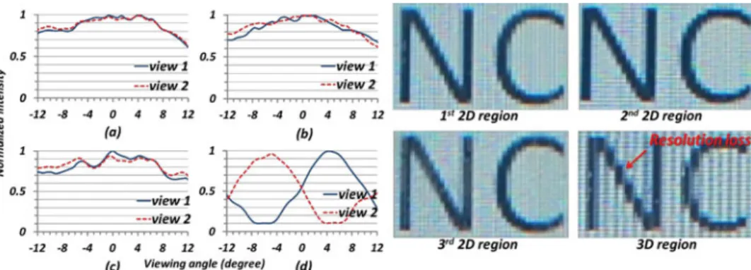
Figure 5. Angular distributions and captured images from the prototype for partial 2D/3D switchable
function in (a) first 2D, (b) second 2D, (c) third 2D and (d) 3D regions.
In the 3D region, the LC distribution has a gradient orientation from vertical direction to horizontal direction to produce lens effect.
3. Experiment Results of 3D Displays
The specification of the prototype is shown in Table 1. For dual-oriented 3D function, the driving voltages are 2Vrms. For partial 2D/3D switchable function, the driving voltages are 2Vrmsfor the bottom electrodes in the 3D region, 6Vrmsfor the bottom electrodes in the 2D region and 4Vrmsfor the top electrodes. The dual-oriented 3D switchable function is verified, according to the angular distributions for horizontal and vertical 3D mode, as shown in Fig. 4.
For partial 2D/3D switching, the 2D regions are divided into three regions according to the different driving conditions. The angular distributions of 2D regions are shown in Fig. 5 (Left a–c). In accordance with the measured data, multifunctional LC lens array can be applied on display devices to supply the partial 2D/3D switching function. In addition, we demonstrate the partial 2D/3D auto-stereoscopic display to show the text in 2D regions and the 3D region. The camera captures the text at the viewing direction with lowest 3D crosstalk. The full resolution of the texts can be displayed in the three 2D regions, as shown in Fig. 5 (Right a–c), respectively. The low resolution of the text is displayed in the 3D region, as shown in Fig. 5 (Right d). It can prove the display can actually show 2D contents with the full resolution.
4. High Dynamic Depth Range (HDDR) of 3D Image Capturing
In the HDDR algorithm, we captured N set of images focused on N-different distance. Each image set has left, center, and right view frames, which provide object disparity to generate the elemental depth map. The object edges are regarded as the indication to judge the object was focused or not. In other words, we applied an edge filter to analogize the region of depth of field. Those areas in where the object edges can pass the Laplacian of Gaussian (LoG) filter will be maintained to HDDR depth map.
In fusion process, once the representative focal point was discovered, we could find the corresponding gray level from the depth map. As a consequence, if N depth of field regions
Figur e 6. Fringing pattern and focusing spot for indi vidually controlled 3× 3 L C-lens array . 271
272 Y.-P. Huang et al.
Figure 7. Elemental images of three focal positions and captured under F/2.8 (a) (b) (c) focus at first
object (d) (e) (f) focus at middle object (g) (h) (i) focus at the last object from left, central and right perspective respectively.
were arranged in capturing, N representative focal points would be extracted. By the same token, N-1 threshold gray value could be decided by averaging the corresponding gray levels of two adjacent representative focal points. According to the result from threshold, we fused those correct regions of depth maps into the HDDR depth map.
Figure 8. Depth maps rendered of (a) HDDR system (b) large f-number (f/22).
3D LC-lens Array 273
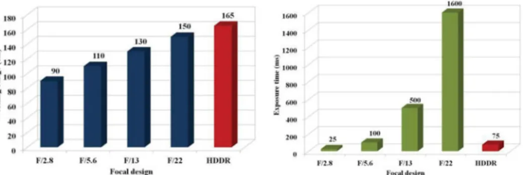
Figure 9. (a) Working range and (b) Exposure time of different focal designs.
5. Experiment Results of HDDR-3D Image Capturing
The experiment results of fringing pattern and focusing spot for individually controlled 3×3 LC-lens array is show in Fig. 6. By using three different focusing length on top, middle, and bottom lenses, the 9 images can be captured respectively, as shown in Fig. 7. Then we could estimate three elemental depth maps of the same screen, but focused on different distance by the DERS software. With HDDR algorithm, those three elemental depth maps are fused into a refined depth map as shown in Fig. 8(a). It shows that HDDR depth map maintained more details such as the doll’s arm and the butterfly wings than the depth map captured with large f-number lens.
The working range of HDDR system is counted from the first object to the terminal wall (200 cm). Apparently, the working range increase with larger f-number, but working range of HDDR using small f-number (F/2.8) is even wider than that of the largest f-number (F/22) of our camera. Furthermore, the exposure time is also minimized as illustrated in Fig. 9. Around 21 times shorter exposure time will benefit the capturing of the instantaneous moments. If spatial HDDR system is implemented, the exposure time will be reduced more and kept the same while stacking more depth of field.
6. Conclusion
To conclude, We successfully achieve a dual-oriented partial 2D/3D switchable auto-stereoscopic display using multi-functional liquid crystal lens array. It can display 2D images without resolution loss and 3D images together. The multi-functional LC lens array has advantages of low driving voltage and easy-fabricated to be compatible with LCD tech-nology. The 3D crosstalks for dual-orientation are 10.8% and 29%. For the 3D capturing, as long as the render depth map is less vulnerable to noise, the performance of HDDR depth map will be better. However, compared to largest f-number of our camera (F/22), HDDR system not only extends to the wider working range 165 cm (>150 cm), but also minimizes the exposure time by around 21 times shorter. And in the following section, we will change the pitch to a reasonable quantity, the size of lens, to verify the feasibility of applying lens array. Moreover, undersigned background is utilized in the scene to meet with more general situation in real word.
274 Y.-P. Huang et al.
Acknowledgment
This work was financially supported by National Science Council, Taiwan, under con-trasts NSC101-2221-E-009-120-MY3, and the polyimide was kindly supported by Chisso Corporation.
References
[1] Uehara, S., Takagi, Kashiwagi, M., & baba, M. (2013). “Function Integrated LC GRIN Lens for Partially Switchable 2D/3D Display”, SID Symp. Dig., Vol. 44, pp. 162–165.
[2] Kashiwagi, M., Uehara, M., Takagi, S., & baba, M., (2013). “LC GRIN Lens Mode with Wide Viewing Angle for Rotatable 2D/3D Tablet”, SID Symp. Dig., Vol. 41, pp. 154–157.
[3] Huang, Y. P. & Chen, C. W. (2012). “Superzone Fresnel Liquid Crystal Lens for Temporal Scanning Auto-stereoscopic Display”, IEEE/OSA Jol. of Display Tech., Vol. 8, No. 11, pp. 650–655.
[4] Huang, Y. P., Liao, L. Y., & Chen, C. W. (2010). “2D/3D Switchable Autostereoscopic Display with Multi-electrically Driven Liquid Crystal (MeD-LC) Lenses”, J. Soc. Inf. Display, Vol. 18, No. 9, pp.642–646.
[5] Kauff, P., Atzpadin, N., Fehn, C., M¨uller, M., Schreer, O., Smolic, A., et al., (2007). “Depth map creation and image - based rendering for advanced 3DTV services providing interoperability and scalability,” Signal Processing: Image Communication, vol. 22, pp. 217–234.
[6] Schulein, R., DaneshPanah, M., & Javidi, B. (2009). “3D imaging with axially distributed sensing,” Optics letters, vol. 34, pp. 2012–2014.
[7] Ng, R., Levoy, M., Br´edif, M., Duval, G., Horowitz, M., & Hanrahan, P. (2005). “Light field photography with a hand- held plenoptic camera,” Computer Science Technical Report CSTR, vol. 2.
[8] Chen, C. W., Cho, M., Huang, Y. P., & Javidi, B. (2012). “Three-dimensional imaging with axially distributed sensing using electronically controlled liquid crystal lens,” Optics Letters, vol. 37, pp. 4125–4127.
[9] Kuang, J., Yamaguchi, H., Liu, C., Johnson, G. M., & Fairchild, M. D. (2007). “Evaluating HDR rendering algorithms,” ACM Transactions on Applied Perception (TAP), vol. 4, p. 9.