Stable and Efficient White Electroluminescent Devices Based on a
Single Emitting Layer of Polymer Blends**
By Ping-I Shih, Ya-Hsien Tseng, Fang-Iy Wu, Ajay Kumar Dixit, and Ching-Fong Shu*
1. Introduction
White organic light-emitting diodes (WOLEDs) have at-tracted a considerable degree of attention because of their po-tential for application in solid-state lighting and backplane lighting for liquid-crystal displays.[1,2] Among these devices, WOLEDs based on semiconductor polymers (PLEDs) are of particular interest because they can be fabricated by spin-cast-ing of the luminescent materials from solution, i.e., by a simpler and, therefore, potentially less expensive, manufacturing pro-cess than those fabrication techniques requiring high-vacuum deposition of small molecules. Various approaches toward— and the challenges associated with—realizing white PLEDs have been reported.[2–11] One approach to obtaining white emission is to use polymeric blend systems containing red-, green-, and blue-light-emitting components. A polymer blend acting as a single emissive layer can be tailored to emit white light through control of the doping level.[2,4–6,8,9]This approach results in devices with simple structures and is therefore attrac-tive because of the possibility of performing low-cost, large-area fabrication. Unfortunately, single-layer-structured white PLEDs have their drawbacks: 1) poor color stability due to phase separation of the different polymer components;[12,13]
and 2) difficulties in controlling the doping level to achieve a balanced white-light emission.[5]
Polyfluorenes (PFs) are very promising candidates for blue-light-emitting materials because of their high photolumines-cence (PL) and electroluminesphotolumines-cence (EL) efficiencies, high thermal stabilities, and ready color tuning through the intro-duction of low-bandgap comonomers.[14–19]In addition, the fa-cile process of functionalizing the C-9 position of the fluorene unit provides the opportunity to tune these materials’ optoelec-tronic properties.[20,21]Moreover, PFs can be used as host mate-rials to generate other colors through energy transfer to lower-energy emitters in blends with other conjugated polymers, fluo-rescent dyes, and organometallic triplet emitters.[5–10,22–25] Con-sequently, PFs can function as both the host and the blue emit-ter in white-light-emitting PLEDs.
In this paper we report white PLEDs formed from polymer blends consisting of blue and orange polyfluorene copolymers. poly{[9,9-bis(4-(5-(4-tert-butylphenyl)-[1,3,4]-oxadiazol-2-yl)- phenyl)-9′,9′-di-n-octyl-[2,2′]-bifluoren-7,7′-diyl]-stat-[9,9-bis(4- (N,N-di(4-n-butylphenyl)amino)phenyl)-9′,9′-di-n-octyl-[2,2′]-bifluoren-7,7′-diyl]} (PFTO) exhibits good spectral stability and a high-efficiency blue emission upon either optical or elec-trical excitation.[21,26] Accordingly, we chose to use PFTO as the polymeric host and blue emitter, which was doped with PFTO-BSeD5, a new orange-emitting polymer that incorpo-rates 5 mol % of narrow-bandgap benzoselenadiazole (BSeD) units into the polyfluorene backbone, to realize white PLEDs. We fabricated white LEDs by spin-coating polymer blends
from a solution containing PFTO and PFTO-BSeD5
(7–11 wt %). Because both the host and dopant polymers pos-sess hole-transporting triphenylamine moieties (TPA units) and electron-transporting oxadiazole moieties (OXD units) in their side chains,[21]leading to a balance between charge
injec-–
[*] Prof. C.-F. Shu, P.-I Shih, Y.-H. Tseng, F.-I. Wu, A. K. Dixit Department of Applied Chemistry, National Chiao Tung University Hsinchu, 300 Taiwan (Taiwan)
E-mail: [email protected]
[**] We thank the National Science Council for financial support. Our spe-cial thanks go to Prof. C.-H. Cheng for his support and cooperation during the preparation and characterization of the light-emitting de-vices. Supporting Information is available online from Wiley Inter-Science or from the authors.
An efficient orange-light-emitting polymer (PFTO-BSeD5) has been developed through the incorporation of low-bandgap benzoselenadiazole (BSeD) moieties into the backbone of a blue-light-emitting polyfluorene copolymer (PFTO poly{[9,9- bis(4-(5-(4-tert-butylphenyl)-[1,3,4]-oxadiazol-2-yl)phenyl)-9′,9′-di-n-octyl-[2,2′]-bifluoren-7,7′-diyl]-stat-[9,9-bis(4-(N,N-di(4-n-butylphenyl)amino)phenyl)-9′,9′-di-n-octyl-[2,2′]-bifluoren-7,7′-diyl]}) that contains hole-transporting triphenylamine and elec-tron-transporting oxadiazole pendent groups. A polymer light-emitting device based on this copolymer exhibits a strong, bright-orange emission with Commission Internationale de L’Eclairage (CIE) color coordinates (0.45,0.52). The maximum brightness is 13 716 cd m–2and the maximum luminance efficiency is 5.53 cd A–1. The use of blends of PFTO-BSeD5 in PFTO leads to efficient and stable white-light-emitting diodes—at a doping concentration of 9 wt %, the device reaches its maximum external quantum efficiency of 1.64 % (4.08 cd A–1). The emission color remains almost unchanged under different bias condi-tions: the CIE coordinates are (0.32,0.33) at 11.0 V (2.54 mA cm–2, 102 cd m–2) and (0.31,0.33) at 21.0 V (281 mA cm–2, 7328 cd m–2). These values are very close to the ideal CIE chromaticity coordinates for a pure white color (0.33,0.33).
FULL
tion and transportation, the resulting devices displayed high luminous efficiencies. Moreover, these two polymers possess very similar chemical structures; therefore, phase separation between the host and dopant is suppressed effectively.[5,27] The Commission Internationale de L’Eclairage (CIE) color coordinates of the observed white light are stable and insensi-tive to both the brightness of the emitted light and the applied voltage.
2. Results and Discussion
2.1. Synthesis and Characterization of PFTO-BSeD5
Scheme 1 illustrates the synthetic route used for the prepara-tion of polyfluorene copolymers possessing bipolar pendent groups. The OXD monomer 1, TPA monomer 2, 4,7-di-bromo-2,1,3-benzoselenadiazole (3), and diboronate 4 were prepared according to reported procedures.[21,28–30]The orange-light-emitting benzoselenadiazole-containing copolymer PFTO-BSeD5 was synthesized through Suzuki coupling of a mixture of dibromides (1, 2, and 3) and the diboronate 4[29]at a mole ratio of 9:9:2:20. The copolymerization was performed using Pd(PPh3)4 (tetrakis(triphenylphosphine)palladium) as the catalyst, in a mixture of toluene and aqueous K2CO3 (2.0M), and in the presence of Aliquat 336 as a phase-transfer
reagent. When polymerization was complete, the end groups of the polymer chain were capped—by heating the mixture under reflux sequentially with phenylboronic acid and bromoben-zene—because boron- and bromine-containing units might quench the emission and contribute to a red-shift of the EL emission in the PLEDs.[31,32]The product was a random copoly-mer with a backbone consisting of fluorene segments of differ-ent lengths separated by a single BSeD unit on both sides of each segment. The selenium content in PFTO-BSeD5
(0.71 wt %), as measured using inductively coupled plasma mass spectrometry (ICP-MS), matched the monomer feed ratio well (0.70 wt %). We prepared the blue-light-emitting polymer PFTO through the copolymerization of monomers 1, 2, and 4, as reported previously.[21]
The polyfluorene copolymer PFTO-BSeD5 is readily soluble in common organic solvents, such as toluene, chlorobenzene, chloroform, and tetrahydrofuran (THF). The weight-average molecular weight (Mw) of the polymer, as determined by gel permeation chromatography (GPC) using polystyrenes as stan-dards, was 10.7 × 10⁴g mol–1, with a polydispersity of 2.9. We investigated the thermal properties of PFTO-BSeD5 through thermogravimetric analysis (TGA) and differential scanning calorimetry (DSC). As revealed by TGA, the polymer exhib-ited good thermal stability, its 5 % weight loss occurring at 364 °C. A distinct glass-transition temperature (Tg) was ob-served at 176 °C; this value is higher than that of PFTO (166 °C), implying that the polyfluorene backbone became more rigid upon the incorporation of the BSeD units in the co-polymer.[29]This relatively high value of Tg may help to
pre-vent morphological changes from occurring upon exposure to heat—an essential characteristic of polymers intended for use as emissive materials in light-emitting applications.[33]
2.2. Optical Properties
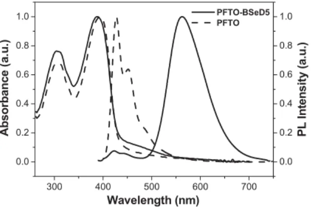
Figures 1 and 2 display the absorption and PL spectra of PFTO-BSeD5 in dilute solution and in the solid state, respec-tively; Table 1 summarizes the spectral data. For the sake of comparison, the absorption and PL spectra of PFTO are also provided. According to the UV-vis absorption spectra in Fig-ures 1 and 2, PFTO-BSeD5 exhibits similar absorption spectral features in THF solution and in the solid state—its two major absorptions appear at ca. 300 and 390 nm. From a comparison
NN O O N N t-Bu t-Bu C8H17 C8H17 N N n-Bu n-Bu n-Bu C8H17 C8H17 X Y N Se N C8H17 C8H17 Z C8H17 C8H17 B B O O O O NN O O N N t-Bu t-Bu Br Br N N n-Bu n-Bu n-Bu n-Bu NSeN Br Br Br Br+ + toluene/H2O/Aliquat 336 Pd(PPh3)4/K2CO3 1 2 3 4 PFTO-BSeD5 X = Y= 0.45n, Z = 0.1n PFTO X= Y = 0.5n, Z = 0 n-Bu +
Scheme 1. Synthesis of the polyfluorene copolymers PFTO-BSeD5 and PFTO. Pd(PPh3): tetrakis(triphenylphosphine)palladium.
P
with the absorption spectra of PFTO, we conclude that the first absorption in the short-wavelength region originates from the combined absorptions of the TPA and OXD pendent groups and that the second arises from a p–p* transition of the conju-gated polyfluorene backbone.[21]In addition, PFTO-BSeD5 ex-hibits a weak absorption at ca. 460 nm, which has been ob-served previously in the absorption spectra of polyfluorene copolymers derived from 9,9-dioctylfluorene and 2,1,3-benzo-selenadiazole.[29] Thus, we attribute this long-wavelength ab-sorption to the presence of the chemically doped BSeD units.
As indicated in Figure 1, the PL spectrum of PFTO-BSeD5 obtained in THF solution at an excitation wavelength of 390 nm is quite different from that of PFTO. We believe that the blue emission, which possesses two vibronic peaks—at 420
and 444 nm—similar to those observed in the PL spectrum of PFTO, arose from the polyfluorenyl chromophoric segments. We attribute the additional longer-wavelength emission band, observed in the orange region, to the narrow-bandgap BSeD units. The effect that the incorporation of BSeD units into the main chain has on the luminescence properties is more dra-matic, however, in thin films. As indicated in Figure 2, the emission from the fluorene segments was suppressed almost completely; instead, the PL spectrum exhibits emission arising predominantly from the BSeD units. We note that the blue-emission region of the polyfluorene segments overlaps signifi-cantly with the absorption region of the BSeD moieties. This overlap should enable energy transfer to occur from the ex-cited polyfluorenyl segments to the lower-energy sites contain-ing the BSeD units. The lack of polyfluorene emission from the film indicates that efficient Förster energy transfer is facilitated through both intra- and interchain interactions, which result from the shorter distances between the polymer chains in the solid state. Consequently, excitons are confined and recom-bined in the BSeD units, which are isolated on both sides by fluorene segments, and the film emits orange light correspond-ing to BSeD emission.
Upon irradiation at 305 nm, a wavelength that corresponds to the absorptions of the pendent TPA and OXD units,[21]the PFTO-BSeD5 film also exhibits an orange emission with a PL spectrum that is perfectly superimposable with that obtained under excitation of the polyfluorene segments at 390 nm. There is no luminescence detectable either from the TPA and OXD side chains at ca. 360 nm or from the fluorene segment chain at 426 nm. These observations indicate that, in addition to direct energy transfer from the excited polyfluorenyl segments to the doped BSeD units, an efficient cascade energy transfer, mediat-ed by the polyfluorene backbone, occurs from the excitmediat-ed TPA and OXD pendent groups to the lower-energy BSeD sites.
2.3. EL Properties of LED Devices
Devices containing PFTO-BSeD5 were fabricated in the configuration ITO/PEDOT:PSS/polymer emitting layer/TPBI/ Mg:Ag/Ag (ITO: indium tin oxide; PEDOT:PSS: poly(styrene-sulfonate)-doped poly(3,4-ethylenedioxythiophene); TPBI: 1,3,5-tris(N-phenylbenzimidazol-2-yl)benzene). The TPBI layer was employed as an electron-transporting layer that would also block holes and confine excitons.[34]Figure 3 indi-cates that the orange-light-emitting device incorporating PFTO-BSeD5 as an emitter exhibits its maximum emission in-tensity at 562 nm in the EL spectra, with a maximum external quantum efficiency (gext) of 1.62 %. The EL spectra, which did not change their appearance upon changing the applied volt-age, were quite similar to the PL spectrum of the PFTO-BSeD5 film; these results indicate that both the EL and PL originate from the same radiative-decay process of singlet exci-tons. In this copolymer, the low-energy BSeN unit is isolated on both sides by fluorene host segments; it functions as an effi-cient trap site to capture excitons through intra- and interchain energy-transfer processes from the high-energy fluorene
seg-300 400 500 600 700 0.0 0.2 0.4 0.6 0.8 1.0 0.0 0.2 0.4 0.6 0.8 1.0 P L I n te ns it y (a.u.) PFTO-BSeD5 PFTO Wavelength (nm) Absorbance ( a .u .)
Figure 1. Absorption and PL spectra of PFTO-BSeD5 and PFTO in dilute
THF solutions. 300 400 500 600 700 0.0 0.2 0.4 0.6 0.8 1.0 0.0 0.2 0.4 0.6 0.8 1.0 PL I n tens it y (a.u.) Wavelength (nm) Absorbance ( a .u .) PFTO-BSeD5 PFTO
Figure 2. Absorption and PL spectra of PFTO-BSeD5 and PFTO in the
sol-id state.
Table 1. Photophysical properties of PFTO-BSeD5 and PFTO.
Solution [a] Film [b]
Absorbance [nm] PL [nm] [c] Absorbance [nm] PL [nm] [c] PFTO-BSeD5 300, 390, 460 420, 445, 570 304, 390, 468 563 PFTO 300, 394 420, 444 305, 394 426, 450
[a] Evaluated in THF. [b] Evaluated in the solid state using films prepared through spin-coating from toluene solutions. [c] Excited at 380 nm.
FULL
P
ments.[29] Consequently, devices prepared from such copoly-mers emit the orange color that is characteristic of the BSeN unit exclusively. Figure 4 presents the current–voltage–lumi-nance (I–V–L) characteristics of the device based on PFTO-BSeD5; Table 2 summarizes the device performance. The
max-imum luminous efficiency (LE) and brightness were 5.53 cd A–1 and 13 716 cd m–2 (at 23.5 V), respectively, with CIE coordinates of (0.45,0.52). This device possesses signifi-cantly improved brightness and efficiency relative to the device prepared from copolymers derived from 9,9-dioctylfluorene and BSeD.[29]We attribute the improved device performance to the greater degree of charge injection and the more efficient charge recombination within PFTO-BSeD5; these improve-ments are due to the presence of the electron-rich TPA and electron-deficient OXD pendent groups. In addition, the intro-duction of the electron-injecting and -transporting TPBI layer, which is also used for hole blocking and exciton confinement, may contribute to the high performance, even though we used a high-work-function alloy of Mg:Ag, rather than Ba, as the cathode.
2.4. White EL from a Binary Blend
PFTO-BSeD5 emits in the orange region of the spectrum, i.e., the region that is complementary to blue light. In principle, if we were to dope this material into a blue polyfluorene, the PL spectrum of the binary blend should cover the whole visible spectrum. Indeed, it should be possible to achieve white-light emission by controlling the doping concentration. Figure 5a displays the EL spectra, recorded at a bias of 11 V, of PLEDs incorporating polymer blends of PFTO doped with 7–11 wt % of PFTO-BSeD5. The EL spectra display a composite of sion bands: the blue emission of the host and the orange emis-sion from the dopant. Both emisemis-sions occur simultaneously from the PLEDs to result in an emission that is close to that of white light. We note that the ratio of the dopant emission to the host emission depends only slightly on the dopant concen-tration. Figure 5b presents the device CIE coordinates for the blends together with those of pure PFTO and PFTO-BSeD5. On the CIE chromaticity coordinate plot, the dotted line join-ing the two polymers’ coordinates passes through the white central region of the CIE diagram of the National Television Systems Committee (NTSC) color system. Upon increasing the dopant concentration from 7 to 11 wt %, the CIE coordinates of the device move correspondingly from (0.29,0.32) to (0.33,0.35), i.e., along the dotted line connecting the coordi-nates of the PFTO emission (0.16,0.09) with those of the PFTO-BSeD5 emission (0.45,0.52). According to the CIE diagram, the emission of the 9 wt % doped device is located precisely in the white central region (0.32,0.33). From the CIE coordinates of these devices, it is clear that two-component white-light-emitting devices can be readily prepared by con-trolling the doping concentration.
To better understand the operating mechanism behind this emission of white light, we used cyclic voltammetry (CV), with ferrocene as the internal standard, to measure the energy levels of PFTO-BSeD5. Based on the onset potentials of the oxida-tion and reducoxida-tion (0.46 and –2.33 V, respectively, vs. a Fc/Fc+ reference), we estimated the highest occupied molecular orbit-al (HOMO) and lowest unoccupied molecular orbitorbit-al (LUMO) energy levels of PFTO-BSeD5 to be –5.26 and –2.47 eV,
re-300 400 500 600 700 800 0.0 0.2 0.4 0.6 0.8 1.0 Wavelength (nm) E L Intensity (a. u .) 11v 15v 21v
Figure 3. EL spectra of the PFTO-BSeD5-based device recorded at various
driving voltages. 4 6 8 10 12 14 16 18 20 22 24 26 0 50 100 150 200 250 300 350 400 450 500 100 101 102 103 104 105 Voltage (V) Current Density (m A /c m 2 ) Bright nes s (c d/ m 2 )
Figure 4. Brightness and current density of devices based on PFTO-BSeD5
plotted as functions of the applied voltage.
Table 2. Performance of devices having the structure ITO/PEDOT:PSS/
polymer emitting layer/TPBI/Mg:Ag.
PFTO-BSeD5 PFTO:
PFTO-BSeD5 [9 wt %]
Turn-on voltage [V] [a] 7.99 9.02
Voltage [V] [b] 13.8 (17.4) 13.1 (16.3)
Brightness [cd m–2] [b] 1099 (4731) 796 (3438)
Luminance efficiency [cd A–1] [b] 5.50 (4.74) 3.99 (3.44)
External quantum efficiency [%][b] 1.61 (1.38) 1.60 (1.38) Maximum brightness [cd m–2] 13716 (@24) 7328 (@ 21V)
Maximum luminance efficiency [cd A–1] 5.53 4.08
Maximum external quantum efficiency [%] 1.62 1.64
Maximum power efficiency [lm W–1] 1.35 1.15
EL maximum [nm] [c] 562 426, 562
CIE coordinates,x and y [c] 0.45 and 0.52 0.32 and 0.33 [a] Recorded at 1 cd m–2. [b] Recorded at 20 mA cm–2; data in parentheses
were recorded at 100 mA cm–2. [c] Recorded at 11 V.
P
spectively, in relation to the energy level of the ferrocene refer-ence (4.8 eV below the vacuum level);[35]these values are very close to the data reported for PFTO (–5.30 and –2.54 eV, re-spectively).[21]The similarity in the values of these HOMO and LUMO levels indicates that the introduction of a small number of BSeD moieties did not affect the electrochemical properties of the resulting polymer. In addition, we did not observe any electrochemical behavior attributable to the BSeD unit in PFTO-BSeD5 because of its low content in the polymer back-bone. Similar phenomena have been observed from studies of fluorine–benzoselenadiazole copolymers.[29] To evaluate the energy levels of the BSeD units embedded in the polyfluorene backbone, we prepared a model compound, 4,7-bis(9,9-dihex-yl-2-fluorenyl)-2,1,3-benzoselenadiazole (BF-BSeD). The ab-sorption and PL spectra of BF-BSeD resembled those of the BSeD units doped in PFTO, with the slightly blue-shifted val-ues of kmax(441 and 563 nm, respectively) being attributed to the shorter conjugation length in the model compound. The HOMO and LUMO energy levels derived from the onset po-tential for the oxidation and the bandgap determined from the optical absorption threshold were –5.56 and –3.14 eV, respec-tively; the inset to Figure 6 illustrates the energy level diagrams
of PFTO and BF-BSeD. These results reveal that the BSeD units cannot serve as trapping sites in the PFTO-BSeD5 poly-mer; this result is quite consistent with the fact that there we observe very few differences between the PL and EL spectra of the PFTO:PFTO-BSeD5 (9 wt %) blend presented in Fig-ure 6.[25]
Figure 7 displays the EL spectra recorded from the 9 wt % doped device at various operating voltages. A significant char-acteristic of our white-light-emitting device—one that is impor-tant for use in display applications—is that the emission color remained almost constant under the different bias conditions. The corresponding CIE coordinates changed only slightly, from (0.32,0.33) at 11.0 V (2.54 mA cm–2, 102 cd m–2) to (0.31,0.33) at 21.0 V (281 mA cm–2, 7328 cd m–2), and they remained very close to those of the ideal CIE chromaticity coordinates for pure white emission (0.33,0.33). This excellent color stability under different operating voltages is in marked contrast to the characteristics of polymer-blend systems and single polymers containing small-molecule dyes; such devices exhibit CIE coor-dinates that are sensitive to the driving voltage,[4,5] probably
300 400 500 600 700 800 0.0 0.2 0.4 0.6 0.8 1.0 (a) Wavelength (nm) EL I nten si ty ( a .u .) 7 wt % CIE(0.29,0.32) 9 wt % CIE(0.32,0.33) 11 wt % CIE(0.33,0.35)
Figure 5. a) EL spectra, recorded at a bias of 11 V, of blends prepared
from PFTO doped with different amounts of PFTO-BSeD5. b) CIE chroma-ticity diagram, with coordinates corresponding to the emissions from devices based on the blends, together with those of pure PFTO and PFTO-BSeD5. The dotted oval indicates the approximate area in which the hu-man eye perceives a white color.
400 500 600 700 800 0.0 0.2 0.4 0.6 0.8 1.0 P L a n d E L Inte nsity (a.u.) Wavelength (nm) EL PL ITO/PEDOT PFTO HOMO
BF-BSeD TPBI Mg/Ag −2.1 −5.2 −5.3 −5.6 −6.2 -3.7 −3.1 −2.7 LUMO
Figure 6. PL and EL spectra of a 9 wt % doped blend. The inset displays
the proposed energy level scheme for devices having the configuration ITO/PEDOT/polymer blend/TPBI/MgAg.
Figure 7. EL spectra and CIE coordinates of a 9 wt % doped
white-light-emitting device operated at various driving voltages.
FULL
P
because of phase separation at high operating voltages.[12,13] In our present study, we prediluted the narrow-bandgap-dye BSeD through chemical doping into the host PFTO to form PFTO-BSeD5, which we then blended with the host to furnish the white-light-emitting material. As a consequence, the chem-ical structure of the PFTO-BSeD5 copolymer is very similar to that of the host; therefore, dye aggregation or phase separation in this blend is suppressed efficiently, leading to a stable, white PLED. We used atomic force microscopy (AFM) to investigate the phase morphologies of pure PFTO and the PFTO:PFTO-BSeD5 (9 wt %) blend. The AFM image (see Supporting Infor-mation) of the 9 wt % doped PFTO film clearly indicated that no phase separation occurred; the root-mean-square surface roughness of the pure PFTO film and the PFTO-BSeD5-doped film were 0.36 and 0.37 nm, respectively. These similar root-mean-square roughnesses for the undoped and doped PFTO films suggest that no detectable phase separation or dye aggre-gation occurred within the PFTO:PFTO-BSeD5 blending sys-tem.[36,37]These results are consistent with the proposed com-patibility between the dopant and host. Another prominent feature of our white PLEDs is that their emission color changed very little under different doping levels (7–11 wt %) because of the chemical predilution of the BSeD dye in PFTO-BSeD5. In previous reports, white PLEDs containing a single emissive layer that had been constructed from a host and a guest were found to be very sensitive to the doping concentra-tion;[5,6,27,38]in other words, it was difficult to control the correct doping level to obtain a balanced white-light emission. In our discussion above regarding the CIE coordinates, we noted that all of the devices prepared using blends containing 7–11 wt % of PFTO-BSeD5 emitted in the white region; therefore, we suggest that such devices are less sensitive to the concentration of the dopant and may possess highly reproducible color puri-ties when these two polymers are used to fabricate white PLEDs.
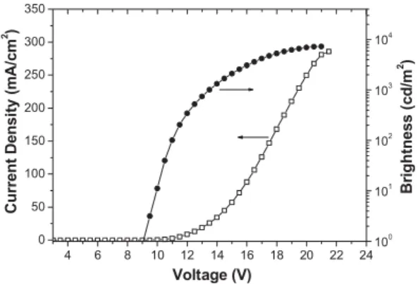
Figure 8 displays the I–V and L–V characteristics of the 9 wt % doped device. The device that was turned on at 9 V (corresponding to 1 cd m–2) exhibited maximum external quan-tum efficiency and luminous efficiency of 1.64 % and 4.08 cd A–1, respectively. When the luminance in our white-light-emitting device was increased to the order of 103cd m–2
(at ca. 25 mA cm–2), ca. 96 % of the value of gext was main-tained; we calculated it to be 1.58 % (3.93 cd A–1). When the brightness was increased further, to nearly 5 × 10³cd m–2 (at ca. 147 mA cm–2), the corresponding EL efficiency was still above 1.3 % (3.2 cd A–1; Fig. 9). Table 2 summarizes the perfor-mance of this white-light-emitting device, which is one of the best electrofluorescent devices based on a single-layer polymer blend that has been reported to date.[2,5,6]We attribute this high performance to the balanced charge injection and transport provided by the PFTO host and the PFTO-BSeD5 dopant.
3. Conclusions
We synthesized an orange-light-emitting polymer (PFTO-BSeD5) by incorporating low-bandgap benzoselenadiazole (BSeD) moieties into a blue-light-emitting polyfluorene co-polymer (PFTO). Bright white-light-emitting diodes based on single-layer polymer blends were fabricated readily through spin-casting of a solution containing PFTO and PFTO-BSeD5 (7–11 wt %). For the 9 wt % doped device, a pure white-light emission having CIE coordinates of (0.32,0.33) was achieved with a high external quantum efficiency and brightness of 1.64 % (4.08 cd A–1) and 7328 cd m–2, respectively. Even when the brightness was increased to 103cd m–2(at ca. 25 mA cm–2), the EL efficiency remained above 1.58 % (3.93 cd A–1). We at-tribute this good performance to the improved charge injection and more-efficient charge recombination of the host and dop-ant polymers, which result from the presence of the electron-rich TPA and electron-deficient OXD pendent groups. More-over, the chromaticity coordinates of the device remained very stable over a relatively wide range of biases (from 11 to 21 V) because of the similar molecular structures of PFTO and PFTO-BSeD5.
4. Experimental
Materials: Monomers 1 [21], 2 [21], 3 [28,29], and 4 [30] and the blue-light-emitting polymer PFTO [21] were synthesized as reported pre-viously. The solvents were dried using standard procedures. All other
4 6 8 10 12 14 16 18 20 22 24 0 50 100 150 200 250 300 350 Voltage (V) Current D ensi ty ( m A/ cm 2 ) 100 101 102 103 104 B rightn e s s ( cd/m 2 )
Figure 8. Current density and brightness plotted as a function of the
volt-age applied to the 9 wt % doped white-light-emitting device.
0 50 100 150 200 250
1 10
Current Density (mA/cm2)
Lumi n a nce ef fi ci ency (cd/ A ) E x te rn al Q u an tu m E ffi ci en c y (% ) 1 10
Figure 9. Luminance efficiency and external quantum efficiency plotted as
a function of the current density for the 9 wt % doped white-light-emitting device.
P
reagents were used as received from commercial sources, unless other-wise stated.
Characterization:1H and13C NMR spectra were recorded on Varian
UNITY INOVA AS500 (500 MHz) and Bruker-DRX 300 (300 MHz) spectrometers. Size exclusion chromatography (SEC) was performed using a Waters chromatography unit interfaced with a Waters 410 differential refractometer; three 5 lm Waters styragel columns (300 mm × 7.8 mm) were connected in series in order of decreasing pore size (104, 103, and 102Å); THF was the eluent. Standard
polysty-rene samples were used for calibration. ICP-MS analysis was per-formed using a Perkin-Elmer SCIEX ELAN 5000 spectrometer. Differ-ential scanning calorimetry (DSC) was performed using a SEIKO EXSTAR 6000DSC unit at a heating rate of 20 °C min–1and a cooling rate of 40 °C min–1. Samples were scanned from 30 to 300 °C, cooled to
0 °C, and then scanned again from 30 to 300 °C. The glass-transition temperatures (Tgs) were determined from the second heating scan.
Thermogravimetric analysis (TGA) was undertaken using a Perkin–El-mer TGA Pyris 1 instrument. The thermal stabilities of the samples were determined under nitrogen atmosphere by measuring their weight losses while heating them at a rate of 20 °C min–1. UV-vis spectra were
measured using an HP 8453 diode-array spectrophotometer. PL spectra were obtained using a Hitachi F-4500 luminescence spectrometer. Cy-clic voltammetry (CV) measurements were performed using a BAS 100 B/W electrochemical analyzer. The potentials were measured against an Ag/Ag+(0.01
MAgNO3) reference electrode using ferrocene as the
internal standard. The onset potentials were determined from the inter-section of two tangents drawn at the rising and background currents of the cyclic voltammogram. Atomic force microscopy measurements were undertaken in the tapping mode using a Digital Nanoscope IIIa instrument under ambient conditions.
Preparation of PFTO-BSeD5: Aqueous potassium carbonate (2.0M, 1.0 mL) and Aliquat 336 (ca. 20 mg) were added to a mixture of mono-mers 1 (64 mg, 73 lmol), 2 (75 mg, 73 lmol), 3 (5.5 mg, 16 lmol), and
4 (104 mg, 162 lmol) in distilled toluene (2.0 mL). The mixture was
degassed and Pd(PPh3)4(ca. 5 mg) was added in one portion under N2.
The solution was then heated at 110 °C for 72 h. The end groups were then capped by heating the mixture under reflux sequentially with benzeneboronic acid (39 mg, 320 lmol) and bromobenzene (50 mg, 320 lmol), each for 12 h. The reaction mixture was then cooled to room temperature and precipitated into a mixture of MeOH and H2O
[1:1 (v/v), 100 mL]. The crude polymer was collected and washed with excess MeOH. This product was dissolved in THF and reprecipitated into MeOH before being washed with acetone for 48 h using a Soxhlet apparatus. Drying under vacuum gave PFTO-BSeD5 (150 mg, 82.5 %).
1H NMR (CDCl 3): d 0.68–0.76 (m, 20H), 0.86–0.91 (m, 12H), 1.06 (br, 40H), 1.33 (br, 26H), 1.54–1.60 (m, 8H), 2.03 (br, 8H), 2.51 (br, 8H), 6.83–7.15 (m, 24H), 7.50–7.85 (m, 30H), 7.94–8.08 (m, 10H) ppm.13C NMR (CDCl3): d 14.66, 14.73, 23.1, 23.2, 24.5, 29.9, 30.7, 31.8, 32.4, 34.3, 35.7, 35.8, 41.0, 56.0, 65.4, 66.5, 120.8, 121.0, 121.7, 121.9, 122.1, 122.5, 123.6, 125.3, 126.7, 126.9, 127.4, 127.9, 128.0, 129.0, 129.5, 129.6, 129.8, 138.2, 138.3, 139.2, 139.5, 139.8, 140.5, 141.0, 141.6, 142.4, 146.0, 147.4, 149.9, 151.5, 152.4, 152.6, 153.5, 156.1, 164.7, 165.4 ppm. 4,7-Bis(9,9-dihexyl-2-fluorenyl)-2,1,3-benzoselenadiazole (BF-BSeD): To a mixture of 4,7-dibromo-2,1,3-benzoselenadiazole (102 mg, 300 lmol), 2-(9,9-dihexyl-7-fluorenyl)-4,4,5,5-tetramethyl-1,3,2-dioxa-borolane (322 mg, 700 lmol), and Aliquat 336 (ca. 9 mg) in toluene (10 mL) was added aqueous potassium carbonate (2.0M, 2.0 mL). The mixture was degassed and Pd(PPh3)4(ca. 5 mg) was added in one
por-tion under N2. The solution was then heated at 105 °C for 12 h. The
reac-tion mixture was cooled to room temperature and water (10 mL) was added to it. The toluene layer was separated and the aqueous layer was extracted with ethylacetate (10 mL × 2). Organic layers were combined and dried over anhydrous MgSO4. The solvent was evaporated under
reduced pressure. The crude product was purified by column chroma-tography, eluting with CH2Cl2/n-hexane (1:4) to afford BF-BSeD
(192 mg, 76 %).1H NMR (300 MHz, CDCl 3): d 0.76–0.80 (m, 20H), 1.02–1.18 (m, 24H), 2.00–2.07 (m, 8H), 7.32–7.41 (m, 6H), 7.72–7.80 (m, 4H), 7.85 (s, 2H), 7.87 (d, 2H, J = 7.8), 7.97 (dd, 2H, J = 7.8, 1.5) ppm.13C NMR (75 MHz, CDCl3): d 14.0, 22.6, 23.8, 29.7, 31.5, 40.3, 55.1, 119.5, 119.9, 122.9, 124.1, 126.8, 127.2, 128.2, 128.4, 135.3, 136.8, 140.7, 141.1,
150.9, 151.2, 160.0 ppm. High-resolution MS (m/z): [M]+ calcd. for C56H68N2Se 848.4548; found 848.4539.
Fabrication of Light-Emitting Devices: Polymer LED devices were fabricated in the configuration ITO/poly(styrenesulfonate)-doped poly(3,4-ethylenedioxythiophene) (PEDOT:PSS) (35 nm)/light-emit-ting layer (80–100 nm)/TPBI (30 nm)/Mg:Ag (100 nm)/Ag (100 nm). To improve both hole injection and substrate smoothness, the PED-OT:PSS was spin-coated directly onto the ITO glass and dried at 80 °C for 12 h under vacuum. The light-emitting layer was spin-coated on top of the PEDOT:PSS layer, using chlorobenzene as the solvent, and then dried for 3 h at 60 °C under vacuum. Prior to film-casting, the polymer solution was filtered through a Teflon filter (0.45 lm). The TPBI layer, which was grown by thermal sublimation in a vacuum of 3 × 10⁻⁶Torr (1 Torr = 133.32 Pa), was used as an electron-transport layer that blocks holes and confines excitons. The cathode Mg:Ag (10:1, 100 nm) alloy was deposited onto the TPBI layer through co-evaporation of the two metals; an additional layer of Ag (100 nm) was deposited onto the alloy as a protection layer. The current–voltage–luminance characteris-tics were measured under ambient conditions using a Keithley 2400 source meter and a Newport 1835C optical meter equipped with an 818ST silicon photodiode.
Received: November 2, 2005 Final version: January 25, 2006 Published online: July 4, 2006
–
[1] J. Kido, M. Kimura, K. Nagai, Science 1995, 267, 1332.
[2] S. Tasch, E. J. W. List, O. Ekström, W. Graupner, G. Leising, P. Schlichting, U. Rohr, Y. Geerts, U. Scherf, K. Müllen, Appl. Phys. Lett. 1997, 71, 2883.
[3] Y.-Z. Lee, X. Chen, M.-C. Chen, S.-A. Chen, J.-H. Hsu, W. Fann, Appl. Phys. Lett. 2001, 79, 308.
[4] B. Hu, F. E. Karasz, J. Appl. Phys. 2003, 93, 1995.
[5] J. H. Kim, P. Herguth, M.-S. Kang, A. K.-Y. Jen, Y.-H. Tseng, C.-F. Shu, Appl. Phys. Lett. 2004, 85, 1116.
[6] Q. Xu, H. M. Duong, F. Wudl, Y. Yang, Appl. Phys. Lett. 2004, 85, 3357.
[7] G. Tu, Q. Zhou, Y. Cheng, L. Wang, D. Ma, X. Jing, F. Wang, Appl. Phys. Lett. 2004, 85, 2172.
[8] H.-J. Su, F.-I. Wu, C.-F. Shu, Macromolecules 2004, 37, 7197. [9] X. Gong, W. Ma, J. C. Ostrowski, G. C. Bazan, D. Moses, A. J.
Hee-ger, Adv. Mater. 2004, 16, 615.
[10] Y. Xu, J. Peng, Y. Mo, Q. Hou, Y. Cao, Appl. Phys. Lett. 2005, 86, 163 502.
[11] S. K. Lee, D.-H. Hwang, B.-J. Jung, N. S. Cho, J. Lee, J.-D. Lee, H.-K. Shim, Adv. Funct. Mater. 2005, 15, 1647.
[12] M. M. Alam, C. J. Tonzola, S. A. Jenekhe, Macromolecules 2003, 36, 6577.
[13] N. Ananthakrishnan, G. Padmanaban, S. Ramakrishnan, J. R. Rey-nolds, Macromolecules 2005, 38, 7660.
[14] M. Leclerc, J. Polym. Sci., Part A: Polym. Chem 2001, 39, 2867. [15] D. Neher, Macromol. Rapid Commun. 2001, 22, 1365.
[16] S. Becker, C. Ego, A. C. Grimsdale, E. J. W. List, D. Marsitzky, A. Po-gantsch, S. Setayesh, G. Leising, K. Müllen, Synth. Met. 2002, 125, 73. [17] C. D. Müller, A. Falcou, N. Reckefuss, M. Rojahn, V. Wiederhirn,
P. Rudati, H. Frohne, O. Nuyken, H. Becker, K. Meerholz, Nature
2003, 421, 829.
[18] C. Ego, D. Marsitzky, S. Becker, J. Zhang, A. C. Grimsdale, K. Mül-len, J. D. MacKenzie, C. Silva, R. H. Friend, J. Am. Chem. Soc. 2003, 125, 437.
[19] R. Yang, R. Tian, J. Yan, Y. Zhang, J. Yang, Q. Hou, W. Yang, C. Zhang, Y. Cao, Macromolecules 2005, 38, 244.
[20] F.-I. Wu, D. S. Reddy, C.-F. Shu, M. S. Liu, A. K.-Y. Jen, Chem. Mater.
2003, 15, 269.
[21] C.-F. Shu, R. Dodda, F.-I. Wu, M. S. Liu, A. K.-Y. Jen, Macromole-cules 2003, 36, 6698.
[22] A. Charas, J. Morgado, L. Alcacer, J. M. G. Martinho, F. Cacialli, Synth. Met. 2003, 137, 1039.
FULL
P
[23] F.-C. Chen, G. He, Y. Yang, Appl. Phys. Lett. 2003, 82, 1006. [24] C. Jiang, W. Yang, J. Peng, S. Xiao, Y. Cao, Adv. Mater. 2004, 16, 537. [25] F.-I. Wu, P.-I. Shih, Y.-H. Tseng, G.-Y. Chen, C.-H. Chien, C.-F. Shu,
Y.-L. Tung, Y. Chi, A. K.-Y. Jen, J. Phys. Chem. B 2005, 109, 14 000. [26] H.-J. Su, F.-I. Wu, Y.-H. Tseng, C.-F. Shu, Adv. Funct. Mater. 2005, 15,
1209.
[27] H. A. A. Attar, A. P. Monkman, M. Tavasli, S. Bettington, M. R. Bryce, Appl. Phys. Lett. 2005, 86, 121 101.
[28] C. W. Bird, G. W. H. Cheeseman, A. A. Sarsfield, J. Chem. Soc. 1963, 4767.
[29] R. Yang, R. Tian, Q. Hou, W. Yang, Y. Cao, Macromolecules 2003, 36, 7453.
[30] M. Ranger, D. Rondeau, M. Leclerc, Macromolecules 1997, 30, 7686. [31] M. Inbasekaran, W. Wu, E. P. Woo, US Patent 5 777 070, 1998.
[32] X. H. Yang, W. Yang, M. Yuan, Q. Hou, J. Huang, X. R. Zeng, Y. Cao, Synth. Met. 2003, 135, 189.
[33] S. Tokito, H. Tanaka, K. Noda, A. Okada, Y. Taga, Appl. Phys. Lett.
1997, 70, 1929.
[34] S. W. Culligan, Y. Geng, S. H. Chen, K. Klubek, K. M. Vaeth, C. W. Tang, Adv. Mater. 2003, 15, 1176.
[35] J. Pommerehne, H. Vestweber, W. Guss, R. F. Mahrt, H. Bässler, M. Porsch, J. Daub, Adv. Mater. 1995, 7, 551.
[36] F.-C. Chen, S.-C. Chang, G. He, S. Pyo, Y. Yang, M. Kurotaki, J. Kido, J. Polym. Sci., Part B: Polym. Phys 2003, 41, 2681.
[37] E. B. Namdas, A. Ruseckas, I. D. W. Samuel, S.-C. Lo, P. L. Burn, J. Phys. Chem. B 2004, 108, 1570.
[38] I. Tanaka, M. Suzuki, S. Tokito, Jpn. J. Appl. Phys., Part 1 2003, 42, 2737.