國立交通大學
工業工程與管理學系
博士論文
以機器視覺為基礎之內螺紋自動檢測系統
Automated Internal Thread Inspection System Using Machine Vision
研 究 生:陳思翰
指導教授:彭德保 博士
以機器視覺為基礎之內螺紋自動檢測系統
Automated Internal Thread Inspection System Using Machine Vision
研究生:陳思翰 指導教授:彭德保 博士 Student: Ssu-Han Chen Advisors: Dr. Der-Baau Perng
國立交通大學
工業工程與管理學系
博士論文
Department of Industrial Engineering and Management College of Management
National Chiao Tung University In Partial Fulfillment of the Requirements
For the Degree of Doctor of Philosophy In
Industrial Engineering and Management February 2010
Hsinchu, Taiwan, Republic of China
I
以機器視覺為基礎之內螺紋自動檢測系統
學生:陳思翰 指導教授:彭德保 博士國立交通大學工業工程與管理學系
摘要
由於內螺紋(Internal Thread)特殊的結構與空間位置的限制,目前尚未發現以機器視 覺為基礎的內螺紋檢測機台。本研究發展一套光學螺紋塞規(Optical Thread Plug Gauge, OTPG),可對內螺紋工件進行非接觸式的自動化檢測。OTPG乃以硬式工業內視鏡(Rigid Industrial Endoscope)及電荷耦合元件(Charge Coupled Device,CCD)組成取像光學模組, 並透過觸發器(Trigger)與兩組馬達控制單元(Motion Control Unit)搭配,逐步拼貼連續拍 攝到的部分螺紋影像,以重建出360度內螺紋壁的二維全周影像圖(Unwrapped Image), 接著,運用影像處理技術、以離散餘弦轉換(Discrete Cosine Transformation,DCT)為基礎之影像還原技術進行影像正規化、影像切割與瑕疵突顯。OTPG可偵測出螺紋坡(Flank)
上凸起狀的刮痕(Scratch),以及螺峰(Crest)或螺谷(Root)上凹陷狀的崩塌(Collapse)或裂痕 (Flaw)。
關鍵詞:內螺紋、硬式工業用內視鏡、電腦視覺、條狀性紋理、離散餘弦轉換、影像還 原
II
Automated Internal Thread Inspection System Using Machine Vision
Student: Ssu-Han Chen Advisors: Dr. Der-Baau Perng
Institute of Industrial Engineering and Management
National Chiao Tung University
Abstract
This dissertation is to design and develop a novel optical thread plug gauge (OTPG) for internal thread inspection using machine vision. The OTPG is composed of a rigid industrial endoscope, a charge-coupled device (CCD) camera, and a two degree-of-freedom motion control unit. A sequence of partial wall images of an internal thread are retrieved and reconstructed into a two-dimensional unwrapped image. Then, a digital image processing, discrete cosine transformation-based image restoration scheme is used to normalize image, segment image, and enhance defect of the internal thread. The proposed OTPG provides an orientation-free and convenient method for detecting defects such as scratches, collapses, and flaws in an internal thread.
Keywords: internal thread, rigid industrial endoscope, machine vision, directional texture,
III
Contents
摘要...I Abstract... II Contents...III List of Figures... V List of Tables ... VII List of Symbols... VIII1 Introduction ...1
1.1 Introduction...1
1.2 Objectives...4
1.3 Organization of the dissertation ...5
2 Literatures Review...6
2.1 Non-contact internal thread inspection systems...6
2.2 Applications of rigid industrial endoscope ...9
2.3 Surface registration from a sequence of 2D images ...10
2.4 Surface inspection for directional textures... 11
3 Research Method...14
3.1 OTPG hardware ...14
3.2 Registration of the 2D unwrapped image ...17
3.3 OTPG algorithm...19
3.3.1 Unwrapped image normalization...19
3.3.2 Normalized image segmentation ...22
3.3.3 Thread pattern blurring...24
3.3.4 Defect extraction ...27
IV
4.1 Repeatability property of the normalized image...30
4.2 Sensitivity analysis of parameter settings ...32
4.2.1. Effects of the structure element size of grayscale closing operator k1 and the offset constant k2 ...32
4.2.2. Effect of the high-energy threshold k3 ...34
4.2.3. Effect of the control constant k4...37
4.3 Experimental results...40
5 Conclusions and Further Researches...46
5.1 Conclusions...46
5.2 Further Researches...47
V
List of Figures
Figure 1: Characteristic parts of internal thread geometry……… 1
Figure 2: Various types of internal threads……… 2
Figure 3: The thread plug gauge……… 3
Figure 4: Reflected light test system……….….…… 6
Figure 5: Magnetic flux leakage test system……….……. 7
Figure 6: Eddy current test system……… 7
Figure 7: Industrial computed tomography test system………...………….. 8
Figure 8: Flowchart of global approach to detecting defects in directional textures……….. 12
Figure 9: Proposed OTPG hardware……… 15
Figure 10: The 90° side-view adaptor……….. 15
Figure 11: Flowchart of the proposed OTPG algorithm……….. 16
Figure 12: A partial wall image of internal thread.……….. 18
Figure 13: Reconstructed 2D unwrapped image of an internal thread……… 18
Figure 14: Unwrapped image normalization procedure……….. 22
Figure 15: Normalized image segmentation procedure……….. 24
Figure 16: Thread pattern blurring and binarization……… 29
Figure 17: Demonstration of repeatability………... 31
Figure 18: Effect of different offset constants………. 33
Figure 19: Average area of blobs generated for different values of k1 and k2……… 34
Figure 20: Average number of blobs generated for different values of k1 and k2………….. 34
Figure 21: Effect of different high-energy threshold values……… 36
Figure 22: Average included angles for different values of k3……… 37
VI
Figure 24: Defect detection results for different values of k4………. 39 Figure 25: Experimental test results of the proposed OTPG………... 44
VII
List of Tables
Table 1: The defects of the internal thread………. 2 Table 2 Ability comparison of the state-of-the-art global directional textured surface defect detectors……….. 13 Table 3: The classification rule of the OTPG algorithm……….. 45
VIII
List of Symbols
Symbol Definition
OTPG Optical Thread Plug Gauge
AOI Automated Optical Inspection PCB Printed Circuit Board
CRT Cathode Ray Tube
OLED Organic Light-emitting Diode TFT-LCD Thin Film Transistor Liquid Crystal Display
IC Integrated Circuit
DFT Discrete Fourier Transform DCT Discrete Cosine Transform DWT Discrete Wavelet Transform
SVD Singular Value Decomposition PCA Principal Component Analysis ICA Independent Component Analysis SPC Statistical Process Control
1
1 Introduction
1.1 Introduction
An internal thread is a spiral screw pattern cut into the inner surface of a hollow cylinder. Figure 1 shows a sectional view of the basic internal thread geometry formed by a sequence of thread patterns. A thread pattern is composed of a crest, a root, and two flanks. The crest, the most prominent part of the thread pattern, is the plateau between the two slanted surfaces. The root is the bottom of the groove between the two slanted surfaces. The flanks are the slanted sides that connect the crest and root; these may be straight or curved.
Figure 1: Characteristic parts of internal thread geometry
The manufacture procedure of an internal thread is to tap the hole by turning the screw tap half turn clockwise and following by quarter turn anti-clockwise till the tapping process is finished. This tapping process allows the material filings to be released from the threads and retains the cutting edges of the screw tap free so as to make taping much easier. However, to keep a high production rate, producers abandon the above tapping steps but only turn clockwise to the end un-intermittently. While in the new tapping process, a screw tap may embed with material filings that shape nonconforming features around the thread with high-risk such as collapses on the crest, scratches on the flank, or flaws on the root. A scratch
2
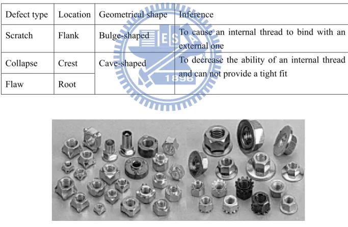
on the flank is a significant bulge that can cause an internal thread to bind with an external one. A collapse on the crest or a flaw deep inside the root will decrease the ability of an internal thread to provide a tight fit. A comparison about the defects of internal thread was tabulated in Table 1. As shown in Figure 2, the internal threads in nuts have a wide variety of sizes, depths, and shapes. Due to the very nature of machine nuts and limited space, visualizing inspecting the crucial features of an internal thread is not a trivial task. Even the inspectors look on sideway; they may not immediately observe the entire pattern yet. Accordingly, some implicit blemishes may be disregarded and it is difficult to guarantee the quality of an internal thread.
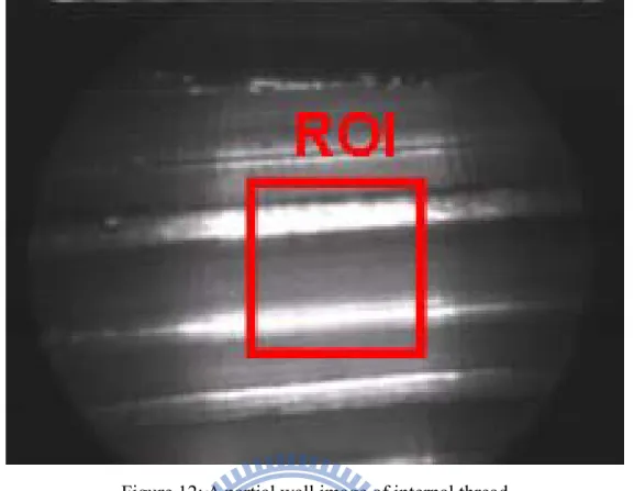
Table 1: The defects of the internal thread Defect type Location Geometrical shape Inference
Scratch Flank Bulge-shaped To cause an internal thread to bind with an external one
Collapse Crest Flaw Root
Cave-shaped To decrease the ability of an internal thread and can not provide a tight fit
Figure 2: Various types of internal threads (from http://www.nuts.com.tw/)
A thread plug gauge as shown in Figure 3 is usually used to check the functionality of an internal thread by screwing the gauge into every thread manually. However, the screwing operation is labor-intensive, time-consuming, and subject to interference. Furthermore, a
3
contact gauge cannot detect certain defects such as collapses or flaws. A non-contact inspection approach is required for the mass production of internally threaded components for the automobile, shipbuilding, and aerospace industries where high precision is required.
4
1.2 Objectives
Machine vision has rarely been used in the inspection of internal threads due to the unique structure and limited space involved. This dissertation is to develop a novel internal thread inspection mechanism that relies on machine vision to create an optical thread plug gauge (OTPG) capable of overcoming the inherent dimensional limitations of internal threads. The proposed OTPG used a rigid industrial endoscope, a CCD camera, and a two degree-of-freedom motion control unit to capture a sequence of partial wall images of an internal thread without any mechanical contact. It also used a 2D image registration method to reconstruct the unwrapped images. Then the digital image processing and discrete cosine transformation-based image restoration scheme are used to normalize image, segment image, and enhance defect of the internal thread.
5
1.3 Organization of the dissertation
This dissertation is organized as follows. In section 2, some related researches, such as the non-contact internal thread inspection systems, endoscope applications, image registration techniques, and the state-of-the-art global directional textures inspectors, are reviewed. In section 3, the hardware structure and the software algorithm of the proposed automated optical inspection (AOI) system are described. In section 4, the experimental environment and results were described. The conclusions and further suggestions are given in section 5.
6
2 Literatures Review
2.1 Non-contact internal thread inspection systems
Some promising new techniques for non-contact internal thread inspection have been developed in recent two decades. Four types of test are briefly described below.
(1) Reflected light test {Hassel [1, 2], Gore [3], Tu et al. [4], Zhao et al. [5], Zhao and Liao [6, 7]}: As show in Figure 4, the mechanism is equipped with a transmitter/receiver probe arranged perpendicular to the thread surface. The transmitter sends a light beam towards the thread, and the reflection goes back to the receiver. The reflectivity is used as a quantifiable feature for defect determination. Field [8] summarized two drawbacks of the reflected light test. First, when thread has been polluted by fluid or oil, varying levels of reflectivity can degrade the detection capability. Second, this technique senses only a small portion of the threaded hole due to the low scanning speed.
Figure 4: Reflected light test system [7]
(2) Magnetic flux leakage test {Wang et al. [9], He et al. [10]}: As shown in Figure 5, a magnetizer magnetizes a part of the internal thread to generate a magnetic leakage field. A detector detects the magnetic leakage field and transforms it into defect signals that can be used to identify defects in threads and mark their positions and ranges. The magnetic flux
7
leakage test, however, can only be used on metal parts.
Figure 5: Magnetic flux leakage test system [9]
(3) Eddy current test {Lin et al. [11]}: As shown in Figure 6, a probe generating an eddy current is inserted into the part with the internal thread. A sensor measures the response signals, which give only a rough indication of the screw defects and positions. Nevertheless, the eddy current test is sensitive to the material's microstructure, hardness, chemistry, temperature, and geometry.
8
(4) Industrial computed tomography test {Liu et al. [12]}: As shown in Figure 7, the tomography of a part is retrieved from multiple directions and the system uses image processing to detect inner faults and measure their geometrical size. As with the reflected light test, this system only scans a small portion of the thread. Moreover, the computed tomography equipment is very expensive.
Figure 7: Industrial computed tomography test system (depicted through the descriptions of [12])
9
2.2 Applications of rigid industrial endoscope
It is impossible for an ordinary detector to look inside small-diameter holes to evaluate internal conditions. George Sumner Crampton developed the first rigid endoscope in 1921 to check for possible flaws inside the rotor of a steam turbine {Lang [13]}. The distinct characteristics of the endoscope are that it can extend the range of vision and change the angle of view to see what could not otherwise be seen. Modern endoscopes are complex, vital non-contact inspection instruments that include an optical-mechatronic sensor and an auto-control scheme. In the past two decades, endoscopes have been used in a wide range of industrial applications. Parenti et al. [14] used them to analyze the combustion in a burner. Tsushima et al. [15] employed them to inspect the inner walls of steel tubes for corrosion. Boudjahi et al. [16] developed an integrated system for detecting micorcacks in pipes. Gu [17] used a video-endoscope in civil aviation maintenance. Biegelbauer et al. [18] proposed a surface reconstruction system for bore holes using an endoscope. Bondarev [19] and Ahn et al. [20, 21] described numerous endoscope applications in the petroleum and gas industry. These papers form a background for using the rigid endoscope in internal thread inspection.
10
2.3 Surface registration from a sequence of 2D images
Image registration is essential to evaluating the global surface texture. Registration aligns two or more images from different sensors or viewpoints. Some studies have used a sequence of 2D images to reconstruct the surface of an object for specific applications such as:
(1) Reconstructing a large object surface: printed circuit board (PCB) {Perng et al. [22]}, cathode ray tube (CRT) panel {Perng et al. [23]}, organic light-emitting diode (OLED) panel {Perng et al. [24]}, or thin film transistor liquid crystal display (TFT-LCD) panel {Chen and Kuo [25]};
(2) Reconstructing a non-flat object surface: bore hole {Biegelbauer et al. [18]} or router {Perng and Chen [26]};
(3) Reconstructing an object surface with high resolution: integrated circuit (IC) chip {Perng et al. [27]}.
Registration techniques have been developed for many different types of problems. In general, the alignment methods can be separated into two categories according to whether two or more aligned images overlap or not. Both categories require close coordination of the sensor and an associated motion unit. For the non-overlapping method, the region of interest (ROI) must exist in two successive but non-overlapping images {Biegelbauer et al. [18], Perng et al. [24]}. For the overlapping method, the ROI must exist in two successive images that overlap by a specified percentage. The users must predefine the overlapping region in the first image as a template and then apply the pattern matching algorithm to the neighboring image {Lewis [28], Fitch et al. [29]}. In the matching process, the predefined template will slide over the entire target image on a pixel-by-pixel or sub-pixel-by-sub-pixel basis so that the maximum matching score can be found and the corresponding alignment coordinate can be determined {Perng et al. [22, 23, 27]}. Although the registration image of the former method may be rougher than the latter one, it is highly computationally efficient and so was used in this dissertation.
11
2.4 Surface inspection for directional textures
A directional textured surface, such as machined part, semiconductor, natural wood, fabric textile, etc. is an object surface which composes of a set of line primitives in some regular or repetitive arrangement over an entire appearance. Detecting local defects embedded in a directional texture surface is one of the popular researches of computer vision. Numerous approaches to auto-inspect the directional textured surface have been proposed, including statistical, structural, global, and model-based approaches {Kumar [30], Xie [31]}. The global approaches are based on image restoration procedure such as using discrete Fourier transform (DFT) {Tsai and Hsieh [32]}, discrete cosine transform (DCT) {Chen and Perng [33]}, discrete wavelet transform (DWT) {Tsai and Chiang [34]}, singular value decomposition (SVD) {Lu and Tsai [35]}, principal component analysis (PCA) {Perng and Chen [36]}, and independent component analysis (ICA) {Lu and Tsai [37]}. Each of these approaches may be a good choice for inspecting directional textured surfaces. Because these approaches require neither textural features nor any reference image for comparison, they are immune to the limitations inherent in local feature extraction or golden template matching methods.
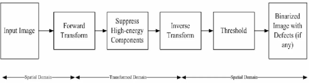
In general, global approaches to inspecting defects in directional textured surfaces usually start with a forward transform and filtering, followed by an inverse transform and thresholding {Kumar [30]}. These approaches all involve implicit qualitative inspection algorithms {Newman and Jain [38]}. Figure 8 shows a flowchart of such a global approach. The input image in the spatial domain is first converted to the transform domain where textures exhibit significant high-energy characteristics that can be detected by some pre-defined criteria. After those specific high-energy components have been suppressed in the transform domain, the inverse transform restores the image to the spatial domain. These global approaches thus preserve only the local defects that existed in the original input image, and remove all directional textures.
12
Figure 8: Flowchart of global approach to detecting defects in directional textures
Detecting defects on the directional textured surfaces is merely one of the basic capabilities. It is prominent, but insufficient, to be discharged in our complex world. So other auxiliary capabilities should be also taken into consideration. Based on the experimental results of existing references [32-37] and experiences, some curial features are summarized in Table 2 to compare the auxiliary abilities of the existing approaches.
As shown in Table 2, the ICA-based approach additionally need golden template and can neither indicate the defect location nor preserve the defect shape. It is also the least adaptive one to tackle the unexceptional evens. The DWT-based approach is good, except it cannot detect the defects that parallel to the texture. Both the texture and such parallel type of defect maps into similar wavelet bank(s) and then be suppressed which usually yields a missed-detection. The remaining approaches, DFT-based, DCT-based, SVD-based, and PCA-based, are relatively outstanding. They can provide with all of the mentioned auxiliary capabilities. Among of them, ICA-based approach needs less memory locations and shows more efficient in computation due to it all deals with real number and has fast DCT algorithm. Based on this reason, an image restoration process based on DCT was used in this dissertation.
13
Table 2 Ability comparison of the state-of-the-art global directional textured surface defect detectors
DFT DCT DWT SVD PCA ICA
Indicate the defect location ○ ○ ○ ○ ○ X
Preserve the defect shape ○ ○ ○ ○ ○ X
Detect the defects that parallel to the texture ○ ○ X ○ ○ ○
Template free ○ ○ ○ ○ ○ X
Shift invariance ○ ○ ○ ○ ○ X
Rotation invariance ○ ○ ○ ○ ○ X
Illumination invariance ○ ○ ○ ○ ○ ○
Suit for line scan system X X X X X ○
14
3 Research Method
3.1 OTPG hardware
The hardware system for internal thread extraction is shown in Figure 9. The sequences of internal thread images were captured by a TELI CS8320 black and white camera with a resolution of 640 × 480 and a Matrox Meteor II frame grabber. A CCD with an illumination less than 0.4 lux is recommended for this task. A 7-in Hawkeye Slim rigid industrial endoscope connected to a 90° side-view mirror tube (as shown in Figure 10) was used as the lens. The outside diameter of the endoscope was only 0.20-in and included a compact illumination fiber. The Moritex MHF-G150LR halogen light source supplied white light to the endoscope to enable the CCD to receive clear images in dark cavities. To overcome the line of sight limitation of the 90° side-view adaptor, the mechanism included a rotational servo motor (SM3416D_PLS) and a linear actuator (SmartT integrated module) to observe all the surfaces of the internal thread at different successive angles and depths. The apparatus was connected to a computer. A flowchart of the proposed vision inspection method is given in Figure 11. The details of this method are described below.
15
Figure 9: Proposed OTPG hardware
16 Start End Unwrapped image normalization for normalized image Image processing by cosine transformation High frequency components elimination by notch-rejected filters Image restoration by inverse cosine transformation Defects extraction by statistical process control binarization
Eliminate the blobs with small areas
Are there pixels out of upper control limit?
Yes No Internal thread unwrapped image grabbing Grade A: good , if N1 = 0 and N2 = 0 Grade B: scratch defect
, if N1 = 1 and N2 = 0 Grade C: collapse or flaw of defect , if N1 = 0 and N2 = 1 Grade D: mixed type defects , if N1 = 1 and N2 = 1 Normalized image segmentation to obtain inspected image Control variables initialization N1 = 0 and N2 = 0 N1 = 1
Are there pixels out of lower control limit?
Yes N2 = 1 No
17
3.2 Registration of the 2D unwrapped image
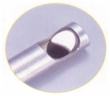
As shown in Figure 12, the inner surface of internal thread can be fully observed by the proposed OTPG. Even so, image distortion and non-uniform illumination will occur due to the inherent endoscope structure and the cylindrical geometry of the internal threads. The farther away the pixels are from the center of the captured image, the more significant the above phenomena will be. Thus, only the region with little distortion near the center of each image for various angles and depths are used. With appropriate control of the sensor and the associated motion unit, a sequence of 150 × 150 pixel low-distortion images by rotating the fixture in 15° steps could be extracted. The ROI of two successive images under these conditions is restricted to only two non-overlapping neighbors. After the fixture has rotated 360°, the linear actuator raises the fixture to the next level and the rotation is repeated. The procedure continues until images of all the inner surfaces of the internal thread have been captured. Finally, the captured sequence of low-distortion images is used to reconstruct a 2D unwrapped image with size 3600 × 1500. It needs 24 × 10 = 240 sub-images to completely registrate one internal thread with 15.3mm in diameter and 20mm in length. Figure 13 shows the reconstructed 2D unwrapped image of an internal thread obtained by the described approach. In this figure, the crest and root of the internal thread correspond to the wide and narrow white bands, respectively. The flanks of the internal thread appear as gray bands. A complete thread pattern is composed of a wide white band, a gray band, a narrow white band, and another gray band in that order. The inner surface of an internal thread is indeed a type of directional texture that comprises repetitive and periodic thread patterns.
18
Figure 12: A partial wall image of internal thread
19
3.3 OTPG algorithm
The most common defects in internal threads are collapses on the crest, scratches on the flank, and flaws in the root, as shown in Figure 14. A scratch usually appears as a bulge that will cause an internal thread to bind with an external one, while a collapse or flaw appears as a cavity that will decrease the tight fit of a thread. This section focuses on developing an auto-inspection software, OTPG algorithm, to detect those defects that are embedded in homogeneous thread patterns. An implicit qualitative inspection algorithm is used to detect the embedded defects. The OTPG algorithm includes four major operations: unwrapped image normalization, normalized image segmentation, thread pattern blurring, and defect extraction. These are discussed below.
3.3.1 Unwrapped image normalization
Because the internal thread is at some arbitrary orientation in relation to the OTPG fixture during defect inspection, the start point of the tapping process in the reconstructed unwrapped image will appear at some random location. To ensure that the relative position of the global structure of each unwrapped image coincide, a process that can automatically reorient the start point of the tapping process in the unwrapped image was developed so it is always on the right-hand side of the image. The procedure of normalizing the unwrapped image is described below and illustrated in Figure 14.
The key to normalizing an unwrapped image is to find the start point of the tapping process of the internal thread and place it on the right-hand side of the image. To do this requires a good binary image where the foreground is composed of white bands (crests and roots) and the background is composed of gray bands (flanks). In addition, to locate the initial root in the binary image is necessary. The initial root is generated early in the thread tapping process. Therefore, if the intensity of each pixel of the binary image was tracked one-by-one, scanning from left to right and top to bottom, the frontier foreground element and the corresponding eight-connected elements must be the initial root.
20
Figure 14(a) shows an initial reconstructed unwrapped image of an internal thread. The grayscale closing operator with structure element size k1 × k1 was first applied to fix the interspaces and fill up the holes; the result is shown in Figure 14(b). Then the grayscale image of Figure 14(b) was converted to a binary image using a threshold value calculated with Equation (1) to separate the crests and roots from the flanks,
( )
k2 maxvalue
threshold = G − (1) where G is the universal set of gray values of Figure 14(b) and k2∈[1, max(G) – 1] is an offset constant. This produces the binary image of Figure 14(c). In Figure 14(c), each eight-connected foreground element can be regarded as a blob and apply a row-by-row labeling algorithm from left to right and top to bottom. The row-by-row labeling algorithm is guaranteed to find the initial root of an internal thread because it is the first one to be produced in the tapping process. The blob of the initial root is labeled as the index one and its corresponding right-bottom coordinate (x*, y*), the start point of the tapping process, is recorded as shown in Figure 14(d). Then the coordinate (x*, y*) was mapped onto the unwrapped image of Figure 14(a) and this image was divided into left and right sub-images, as shown in Figure 14(e), based on the x* coordinate. The unwrapped image can be rounded arbitrarily due to the intrinsic cylindrical structure of the internal thread. A normalized image by rounding the coordinate of the start point to the right-hand side was obtained, as shown in Figure 14(f).
21 (b)
(c)
(d)
22 (f)
Figure 14: Unwrapped image normalization procedure: (a) unwrapped image, (b) morphological image, (c) binary image, (d) labeled image where the blob with index one is regarded as the initial root of the thread and its corresponding right-bottom coordinate (x*, y*) is the start point of the tapping process, (e) division of the unwrapped image into left and right sub-images based on the (x*, y*) coordinate, and (f) normalized image generated from rounding the coordinate of the start point in (e) to the right-hand side
3.3.2 Normalized image segmentation
Note that the first two and the last thread patterns of an internal thread can be ignored because the beginning and ending stages of the tapping process form relatively unstable and abnormal patterns. Moreover, these thread patterns are not important in the interaction with an external thread for creating a firm fastening. Here, only the remaining thread patterns, named the inspected image, in the normalized image are focused and an automatic segmentation process can be developed. The normalized image segmentation procedure is explained below and illustrated in Figure 15.
The inner surface of an internal thread comprises repetitive and periodic thread patterns. A scan along the line that extends from the top to the bottom in the vertical direction of (x*, y*) in Figure 14(d) will touch on the initial root first, followed by the initial crest, followed by the second root and then the second crest, etc. This is the ideal case, however, because some noise blobs may interrupt the regularity. Thus an efficient sub-operation for eliminating the
23 noise blobs is necessary.
Based on the results of Figure 14(d), a binary image where each blob has a unique labeling index was obtained. However, there are still some noise blobs in Figure 14(d). To eliminate them, two properties of each blob: the area and the angle were extracted. The areas of blobs were conveyed into the 1D and two groups clustering formula of {Liu and Tsai [39]} to find out the representatives of noises and crests/roots. The blobs with areas that were closer to the smaller area representative were regarded as ignoring areas and could be removed. Then the mode of the angles of the remaining blobs was estimated. Each angle was rounded to the second decimal place. The remaining blobs with angles that were distinct with the mode were regarded as blobs with irregular angle and could be removed. In sum, the noise blobs with a small area or irregular angle relative to the angle of the crests and roots are eliminated. When the blob elimination sub-operation was applied on Figure 14(d), a clear labeled image can be obtained as shown in Figure 15(a). Then by scanning along a line that stretches from the top to bottom of the image in the vertical direction of (x*, y*), the top coordinates of the third- and second-last roots could be recorded. Based on the coordinates of the third- and second-last roots, upper and lower segmented bounds along the horizontal direction, as shown in Figure 15(b) could be determined. Finally, the normalized image is trimmed based on these two segmented bounds, as shown in Figure 15(c), and the corresponding inspected image of size m × n is auto-segmented, as shown in Figure 15(d).
24 (b)
(c)
(d)
Figure 15: Normalized image segmentation procedure: (a) start with a clear labeled image where the noise blobs have been eliminated, (b) find the third and second-last roots, (c) map two segmented bound onto the normalized image of Figure 14(f), and (d) obtain final image to be inspected
3.3.3 Thread pattern blurring
Up to the present, a set of directional textures in the image was obtained and can be inspected. The DCT-based image restoration technique is well-suited for detecting defects in directional textures. Intuitively, the dominating direction of the thread pattern in the inspected
25
image will correspond to orthogonal straight lines throughout the origin of the DCT spectrum. The lines associated with high-energy frequency components in the spectral domain are eliminated by reducing them to zero and transforming back to the spatial domain. The procedure will blur all thread patterns and preserve only local defects if they are initially embedded in the inspected image.
3.3.3.1 Inspected image processing by discrete cosine transformation
As shown in Figure 15(d), the thread patterns of the inspected image appear as a type of periodic directional texture. The periodically occurring thread patterns were first characterized according to their frequency components. Several DCT variants have been proposed. These were categorized by Wang into four slightly different transformations: DCT-I, DCT-II, DCT-III, and DCT-IV [40]. The DCT-II was used in this research because of its ability to process images with uneven boundaries. Let f(x, y) be the gray level of the pixel at (x, y) in the inspected image of size m × n. The discrete 2D DCT is,
( ) ( ) ( )
=∑∑
−( )
⎢⎣⎡(
+)
⎥⎦⎤ ⎢⎣⎡(
+)
⎥⎦⎤ = − = n v y m u x y x v u v u m x n y 2 π 1 2 cos 2 π 1 2 cos , f α α , C 1 0 1 0 (2)for u = 0, 1, …, m–1 and v = 0, 1, …, n–1, where α(u) and α(v) are defined as
( )
( )
⎪ ⎪ ⎩ ⎪⎪ ⎨ ⎧ = = = ⎪ ⎪ ⎩ ⎪⎪ ⎨ ⎧ = = = 1 -, 1,2, , 2 0 , 1 α 1 -, 1,2, , 2 0 , 1 α n v n v n v m u m u m u K K . (3)As shown in Figure 16(a), the global thread patterns are easily distinguishable as a concentration of high-energy lines in the spectrum that are orthogonal to the direction of thread pattern in Figure 15(d).
26
The forward DCT was then applied on Figure 15(d) and the spectra was obtained as shown in Figure 16(a); Figure 16(b) showed the corresponding 3D energy plots. The dominant directions in Figure 15(d) were compacted to orthogonal straight lines through the direct current (DC) component, as shown in the corresponding Figures 16(a) or 16(b). In addition, Figures 16(a) or 16(b) clearly showed that the high-energy frequency components are packed around the top left regions. These are all inherent characteristics of the DCT basis function.
3.3.3.2 High-energy frequency components elimination
Since thread patterns and scratch defects are oriented in the same direction in the inspected image, the thread patterns are mixed together with the orthogonal lines in the spectrum. Since orthogonal lines may be due to both thread patterns and scratches, using a band-rejected filter to eliminate the orthogonal is not good approach. In this dissertation, the wide dynamic range of C(u, v) was first mapped into the narrow range of P(u, v) by a logarithmic transformation, and scaled its intensity into an eight-bit gray level using
( )
[
(
( )
2)
]
, C 1 log , Pu v =S + u v (4)where S(·) is a scaling operation. Some high-energy frequency components in the spectrum image can then be determined in terms of a high-energy threshold, and are set to zero described in,
( )
( )
( )
⎩ ⎨ ⎧ ≥ = otherwise , , C k3 , P if , 0 , Ck3 v u v u v u (5)where k3∈[1, 255] is a high-energy threshold. The resulting image is shown in Figure 16(c) and the corresponding 3D energy plot is shown in Figure 16(d).
3.3.3.3 Image restoration using inverse discrete cosine transformation (IDCT)
After eliminating the specific high-energy frequency components, the spectrum image was back transformed into the spatial domain using the IDCT,
27
( )
=∑∑
−( ) ( ) ( )
⎢⎣⎡(
+)
⎥⎦⎤ ⎢⎣⎡(
+)
⎥⎦⎤ = − = n v y m u x v u v u y x m u n v 2 π 1 2 cos 2 π 1 2 cos , C α α , fˆ 1 0 1 0 k3 (6)for x = 0, 1, …, m–1 and y = 0, 1, …, n–1, where α(u) and α(v) are defined in Equation (3). In Figure 16(e), it is observed that the homogenous thread patterns have been blurred and the associated gray levels have been compressed into a uniform and limited range. Conversely, the gray levels of scratches on the flank in Figure 15(d) have been retained, as shown in Figure 16(e). Meanwhile, the gray levels of collapses on the crest or flaws in the root in Figure 15(d) have been reduced, as also shown in Figure 16(e).
3.3.4 Defect extraction
Since the scratches are relatively brighter and the collapses or flaws are relatively darker than the blurred thread patterns in the restored image, as shown in Figure 16(e), the statistical process control (SPC) binarization method [32] could be used to set the upper and lower control limits for determining defects from the uniform thread patterns. The SPC binarization method can be described by,
( )
( )
⎪⎩ ⎪ ⎨ ⎧ − ⋅ < < + ⋅ = o.w. 0 fˆ σ k4 fˆ μ y x, fˆ fˆ σ k4 fˆ μ if 255 y x, fˆ (7)where k4 is a control constant; μfˆ and σfˆ are the mean and standard deviation, respectively, of the gray level in the restored image. If a pixel has a gray level that falls between the upper and the lower limits, it is shown as white and is considered to be a thread element that should be removed. Otherwise, it is shown as black and is considered to be a defective element that should be preserved. The result of applying the SPC binarization method on Figure 16(e) is shown in Figure 16(f). Finally, the connected component labeling operator with 8-adjacent is implied again which will have the noise blobs with small areas be removed
28 (a)
(b)
(c)
29 (e)
(f)
Figure 16: Thread pattern blurring and binarization: (a) the spectra of Figure 15(d), (b) the 3D energy plots of Figure 16(a), (c) the filtered spectra of Figure 16(a) when k3 = 55, (d) the 3D energy plots of Figure 16(c), (e) the restored images, (f) the binarized image
30
4 Experiments and Discussion
In subsection 4.1, the repeatability property of the normalized image was described. A sample internal thread was placed at three arbitrary orientations to test the repeatability of the normalization. In subsection 4.2, some preliminary experiments to evaluate the impact of different values of these parameters were described. In subsection 4.3, ten samples of good and defective internal threads are used to demonstrate the inspection results of the proposed OTPG. Forty-four samples are used to evaluate effectiveness and robustness of the proposed OTPG.
4.1 Repeatability property of the normalized image
To demonstrate the repeatability property of the normalized image, the user can place the internal thread on the fixture at any arbitrary orientation. The original sequence of images is reconstructed by rounding the start point of the tapping process of the unwrapped image to the right-hand side. As shown in Figures 17(a)-(c), three unwrapped images were reconstructed in arbitrary orientations. The three images differed only in their relative position. Applying the proposed image normalization procedure normalized all these images in the same manner, as shown in Figure 17(d). This shows that our normalization procedure can successfully normalize the unwrapped image so that the start point of the tapping process is always on the right-hand side. Such image position normalization also provides a uniform inspected image for defect detection.
31 (a)
(b)
(c)
(d)
Figure 17: Demonstration of repeatability: (a) first unwrapped image, (b) second unwrapped image, (c) third unwrapped image, and (d) corresponding normalized image
32
4.2 Sensitivity analysis of parameter settings
As implemented the OTPG algorithm described in section 3.3 has four major parameters that influence the inspection outcome: the structure element size of grayscale closing operator k1, the offset constant k2, the high-energy threshold k3, and the control constant k4.
4.2.1. Effects of the structure element size of grayscale closing operator k1 and the offset constant k2
The parameter k1 is the rectangular size of the structure element of grayscale closing operator that can mend the interrupted crests or roots in the internal thread image. The parameter k2 is an offset constant that can adjust the binary threshold value in Equation (1) to enable the user to reveal the pixels with gray levels between max(G) – k2 and max(G) in Figure 14(a). The bright bands (crests or roots) and gray bands (flanks) in the morphological image of the internal thread can be well mended and totally separated if both k1 and k2 are selected properly. That permits the analysis of the normalization and segmentation procedures in subsections 3.3.1 and 3.3.2 to proceed successfully. As shown in Figures 18(a)-(c), as the value of k1 or k2 increases, there are more and more crests and roots will join into the connected blobs. On the contrary, as the value of k1 or k2 decreases, neither the crest nor the root will be well shaped or well mended. Those blobs will appear as false crests or roots so that the image of the internal thread will be ambiguous and complicated for later processing.
33 (b)
(c)
Figure 18: Effect of different offset constants: (a) k1 = 10 and k2 = 7,(b) k1 = 50 and k2 = 11, and (c) k1 = 100 and k2 = 15
To obtain reliable values of k1 and k2, a supervised pre-training session was conducted on 22 samples. Figure 19 and Figure 20 showed the curves of the average area of blobs and the average number of blobs after the blob elimination sub-operation described in subsection 3.3.2 was applied for different combinations of k1 and k2. The curves of different k1 in Figure 19 were dramatically inflating when the values of k2 were larger than 25. Meanwhile, in Figure 20, these curves were decreasing when the values of k2 were larger than 14 due to the bright and gray bands have gradually joined together. The intersection of the intervals, (k2 ≧ 25) ∩ (k2 ≧ 14), was took the complement which yielded an interested region, k2 < 14, to be following discussed. When k1 was smaller than 5, the average area of blobs were relative low and the averages number of blobs were relative high due to interrupted crests or
34
roots were not well mended and then were partial eliminated. When k1 was in the range of 7-11, the average area of blobs and the average number of blobs were relative stable due to the crests and roots can be well mended and separated from the flanks reliably. When k1 was larger than 13, the average area of blobs were relative high and the average number of blobs were relative low due to some crests or roots have joined together by the large structure element sizes that some blobs will be misinterpreted as false crests, roots, or flanks. In this way, we could get the stable intervals of k1 in the range of 7-11 and k2 less than 14.
Figure 19: Average area of blobs generated for different values of k1 and k2
Figure 20: Average number of blobs generated for different values of k1 and k2
4.2.2. Effect of the high-energy threshold k3
35
components in the spectrum to zero. In general, the smaller the value of k3 is, the greater the numbers of high-energy frequency components are eliminated in the spectrum. A value of k3 that is too large results in an insufficient number the high-energy frequency components of the thread patterns properly to be eliminated and the thread patterns will not be removed completely when the spectrum is converted back to the spatial image. Conversely, when the value of k3 is too small, too many high-energy frequency components that characterize both the thread patterns and defects are eliminated. Thus, the thread patterns and local defects will all be removed in the restored image.
In this experiment, the effect of three different high-energy threshold values on the image in Figures 16(a) was examined; the results are shown in Figures 21(a1)-(a3). Figures 21(b1)-(b3) show the corresponding restored images. In Figure 21(a1) and Figure 21(b1), a smaller value of k3 was selected to eliminate too many high-energy frequency components so that the overall texture and defects were all removed, leaving nothing meaningful. In Figure 21(a2) and Figure 21(b2), an appropriate value of k3 was used to remove the periodic directional texture of the thread pattern while preserving the defects. Note that the eliminated high-energy frequency components were allocated in a direction orthogonal to the thread pattern spread range near the origin of the spectrum image only. In Figure 21(a3) and Figure 21(b3), a large value of k3 was used so that only one high-energy frequency component was eliminated at the origin of the spectrum. Notice that the overall texture was retained in the corresponding restored image.
36 (a2) (a3) (b1) (b2) (b3)
Figure 21: Effect of different high-energy threshold values: (a1)-(a3) show the results of eliminated high-energy frequency components in the spectrum image of Figure 16(a) for k3 =
37
Twenty-two samples were used to calculate the corresponding average angle of the eliminated high-energy frequency components in the DCT domain. The included angles between the angle of thread pattern in the spatial domain and the angle of the eliminated high-energy frequency components in the DCT domain are shown as functions of k3 in Figure 22. The average included angles increased rapidly when k3 was in the range of 1-5. When k3 was in the range of 6-104, the average included angles were approximately orthogonal. When k3 was greater than 105, only one high-energy frequency component was eliminated in the DCT domain so that the corresponding average included angle could not be computed. Experience from the training samples indicates that a value between 6 and 104, where the average included angles are approximately orthogonal, is the most suitable.
Figure 22: Average included angles for different values of k3
4.2.3. Effect of the control constant k4
Since scratches are brighter, and collapses and flaws are darker than blurred thread patterns in the restored image, the SPC binarization concept shown in Equation (7) was used to distinguish between thread patterns and defects. The value of k4 affects the severity of the lower and upper control limits. In general, smaller values of k4 results in tight limits that the thread patterns might not been fully whitened and more noise appears in the binary image, i.e. false alarms. Conversely, a value of k4 that is too large results in a very relaxed standard that may white both the thread patterns and defects and produce missed detections.
38
In this experiment, the effect of three different values of k4 on the image in Figure 16(e) was examined; the results are shown in Figures 23(a)-(c). Figure 23(a) showed the binarized result of Figure 16(e) for k4 = 2. We could observe that the thread patterns were not fully white when the control constant was too small; much noise appeared in Figure 23(a). Figure 23(b) presents the binarized result of Figure 16(e) for k4 = 5. A proper control constant value could produce white thread patterns and dark defects more precisely. The defects were shown clearly in Figure 23(b). Figure 23(c) presented the binarized result of Figure 16(e) for k4 = 8. We could observe that both the thread patterns and defects became white when a large control constant was used. The defects were almost eliminated in Figure 23(c).
(a)
(b)
(c)
Figure 23: The effect of different control constants: (a)-(c) show the binarized image of Figure 16(e) for k4 = 2, 5, and 8, respectively
39
the recommended range of k3, the false alarm phenomenon decreased gradually as k4 increased, and was the inverse of the missed detection phenomenon. Figure 24 also illustrated that SPC binarization yielded satisfactory limits with the highest number of correct detections and lowest number of false alarms and missed detections when k4 was in the range of 5.0-5.2.
40
4.3 Experimental results
In this subsection, some experimental results of internal thread inspection were presented to confirm the function of the proposed OTPG. Figures 25(a1)-(a10) showed the inspected images of good or defective internal threads. The parameters generated from 22 training samples were k1 = 9, k2 = 7, k3 = 55, and k4 = 5.1 (To take the middle values of these corresponding recommended intervals). Figures 25(b1)-(b10) showed the corresponding inspection results. A non-defective internal thread image resulted in a clear response; otherwise defects were clearly indicated in their actual locations. As previously mentioned, a scratch will cause an internal thread to bind with an external one, and a collapse or flaw will decrease the tight fit. The pixels of a scratch were relatively bright and the pixels of a collapse or flaw were relatively dark compared to the blurred thread patterns in the restored image.
Forty-four testing samples (23 non-defective and 21 defective) were tested for evaluating the inspection rate of proposed method. After applying the proposed OTPG algorithm, no any false alarm but only one miss-detection was encountered; this meant that the inspection rate was up to 97.72%. The only miss-detection was due to the scratches on the flanks were small and non-continuous, so they were miss-regarded as small-area noise blobs to be miss-removed.
(a1)
41 (a3) (a4) (a5) (a6) (a7)
42 (a8) (a9) (a10) (b1) (b2)
43 (b3) (b4) (b5) (b6) (b7)
44 (b8)
(b9)
(b10)
Figure 25: Experimental test results of the proposed OTPG: (a1)-(a3) good internal thread, (a4)-(a6) defective internal thread with a collapse, (a7)-(a8) defective internal thread with a collapse and flaw, (a9) defective internal thread with a collapse and scratch, (a10) defective internal thread with a scratch and (b1)-(b10) the resulting binary images corresponding to
(a1)-(a10)
For quality assurance purposes, the internal threads could be classified into four categories as listed in Table 3. First, when no blob existed in the final response image, this was classified as a good grade A internal thread. Second, when a blob existed in the final response image and the corresponding gray levels in the restored image were above the upper limit, this was classified as a scratched defective grade B internal thread that should be reworked by thread tapping to sweep away the bulges on the flanks. The third classification was the same as the second, except the gray levels were below the lower limit; this was
45
classified as a collapsed or flawed defective grade C internal thread that should be tested for close fit by a human expert. Fourth, when an internal thread with a mixture of defects existed, this was classified as grade D for which both rework and fit testing are required.
Table 3: The classification rule of the OTPG algorithm
Grade Criterion Class Action
A number of blobs = 0 good Seller can dispatch the internal thread to customers.
B number of blobs > 0 gray levels > UCL
scratch defect The internal thread should be reworked by thread tapping to sweep away the bulges on the flanks. C number of blobs > 0
gray levels < LCL
collapse or flaw defect
The internal thread that should be tested for close fit by a human expert.
D number of blobs > 1
gray levels > UCL and < LCL
mixed-type defects
Both rework and fit testing are required for the internal thread.
46
5 Conclusions and Further Researches
5.1 Conclusions
A novel OTPG for the auto-inspection of internal threads was proposed in this dissertation that provides a non-contact and an orientation-free internal thread inspection mechanism. The OTPG system captured a sequence of partial wall 2D images of the internal thread and converted them into a 2D unwrapped image. A preprocessing algorithm was designed to achieve repeatability when segmenting the inspected image. A DCT-based restoration technique was implemented to highlight defects such as scratches, collapses, and flaws in the directional texture image. The proposed OTPG can be used to detect both bulge-shaped scratch and cave-shape collapse or flaw.
47
5.2 Further Researches
The reconstructed 2D image loses the depth information of an internal thread pattern. Some crucial features, such as the diameter and lead angle of the internal thread, are beyond the scope of this dissertation. The three-dimensional reconstruction of internal threads to improve automated optical measurement remains a subject for further research.
For the developed prototype OTPG, the inspection time includes image grabbing and image processing. The former takes about 10 minutes and the latter takes less than 6 seconds in inspecting an internal thread with diameter 15.3mm and length 20mm. The image registration time is the bottleneck of the OTPG approach. It is worth studying how to reduce the image registration time for further research.
48
References
[1] Hassel M (1994) A laser-based thread detection system. Sens Rev 14(3):18-19.
[2] Hassel M (1995) Laser-based feature detection system including internal thread detection. IEEE/IAS Int Conf Ind Autom Control Emerg Technol 567-568. doi: 10.1109/IACET.1995.527621
[3] Gore M (1996) Internal thread inspection with capacitive sensors. Sens 12:48-49.
[4] Tu DW, Tao J, Qi S (1998) Computer-aided internal thread parameters testing. Proc SPIE 3558:234-238. doi:10.1117/12.318391
[5] Zhao Y, Li PS, Pu ZB (1999) MJ internal thread used for aerospace and its non-contact test method with a fiber optic sensor. Proc SPIE 3740:501-504. doi:10.1117/12.347727 [6] Zhao Y, Liao YB (2002) Single-mode fiber-based reflex sensor for internal surface
in-line measurement of small products. Sens Actuators A Phys 101(1-2):30-36. doi:10.1016/S0924-4247(02)00143-7
[7] Zhao Y, Liao YB (2003) Research on measurement technology of internal MJ threads used for aerospace with a reflex fiber-optic sensor. Opt Eng 42(2):416-420. doi:10.1117/1.1532742
[8] Field RH (2000) Detecting threads in machined holes: a look at eddy-current and other promising new probes. Manuf Eng 124(6):96, 98, 100-101.
[9] Wang XM, He J, He FY (2002) Leakage magnet detection system for inside screw steel pipes and flaw identification. Heavy Mach 6:18-21. (In Simplified Chinese)
[10] He FY, He J, Chen HD (2003) Inspection of the screw inside steel pipes and the testing system. Nondestruct Test 25(7):343-345, 368. (In Simplified Chinese)
[11] Lin JM, Lee TB, Lei H, Zheng Y (2005) The rotate and scan technique of eddy current test on screw and internal thread inspection. Nondestruct Insp 29(5):28-31. (In Simplified Chinese)
49
[12] Liu QM, Wang LS, Chen XW, Cui Z (2005) Non-damage measurement on internal taper thread of electrode. Opt Tech 31(2):309-314. (In Simplified Chinese)
[13] Lang WJ, George S (1988) Crampton and the origins of industrial endoscopy. Mater Eval 46: 1639-1642.
[14] Parenti R, Verrecchia P, Bosla G, Pignone E (1994) Industrialized real-time flame thermal thermal mapping system with off-line correction of spatial error. IEEE Int Conf Ind Electron Control Instrum 3:1977-1980. doi: 10.1109/IECON.1994.398122
[15] Tsushima T, Ishii A, Ochi Y, Masaoka N, Matsusue N (1997) Corrosion inspection of steel tube inner wall. IEEE/ASME Int Conf Adv Intell Mechatron 34. doi: 10.1109/AIM.1997.652892
[16] Boudjahi S, Ferreira A, Krupa A (2003) Modeling and vision-based control of a micro catheter head for teleopcrated in-pipe inspection. IEEE Int Conf Rob Autom 3:4282-4287. doi: 10.1109/ROBOT.2003.1242262
[17] Gu HT (2003) Industrial videoprobe’s application in Chinese civil aviation maintenance. Test Equip Technol 6:56-57. (In Simplified Chinese)
[18] Biegelbauer G, Vincze M, Nohmayer H, Eberst C (2004) Sensor based robotics for fully automated inspection of cores at low volume high variant parts. IEEE Int Conf Rob Autom 5: 4852-4857. doi: 10.1109/ROBOT.2004.1302486
[19] Bondarev OY (2004) Application of industrial endoscope for the testing of a technical condition of a petroleum and gas industry objects. Kontrol’ Diagn 3:23-25.
[20] Ahn J, Schobeiri MT, Han JC, Moon HK (2006) Film cooling effectiveness on the leading edge region of a rotating turbine blade with two rows of film cooling holes using pressure sensitive paint. J Heat Transf 128(9):879-888. doi: 10.1115/1.2241945
[21] Ahn J, Schobeiri MT, Han JC, Moon HK (2007) Effect of rotation on leading edge region film cooling of a gas turbine blade with three rows of film cooling holes. Int J Heat Mass Transf 50(1-2):15-25. doi:10.1016/j.ijheatmasstransfer.2006.06.028
50
[22] Perng DB, Liu CP, Chen YC, Chou CC (2002) Advanced SMD PCB vision inspection machine development. 15th IPPR Conf Comput Vis Graph Image Process 311-317.
[23] Perng DB, Chou CC, Chen WY (2007) A novel vision system for CRT panel auto-inspection. J Chin Inst Ind Eng 24(5):341-350.
[24] Perng DB, Chen YC, Lee MK (2005) A novel AOI system for OLED panel inspection. J Phys Conf Ser 7th Int symp Meas Technol Intell Instru 13(1):353-356.
[25] Chen LC, Kuo CC (2008) Automatic TFT-LCD mura defect inspection using discrete cosine transform-based background filtering and ‘just noticeable difference’ quantification strategies. Meas Sci Technol 19(1):015507. doi: 10.1088/0957-0233/19/1/015507
[26] Perng DB, Chen YC (2009) An Advanced Auto-Inspection System for Micro-router Collapse. Mach Vision Appl (Accepted)
[27] Perng DB, Chou CC, Lee SM (2007) Design and development of a new machine vision wire bonding inspection system. Int J Adv Manuf Technol 34(3-4):323-334. doi: 10.1007/s00170-006-0611-6
[28] Lewis JP (1995) Fast normalized cross-correlation. Vis Interface 120-123.
[29] Fitch AJ, Kadyrov A, Christmas WJ, Kittler J (2005) Fast robust correlation. IEEE Trans Image Process 14(8):1063-1073. doi: 10.1109/TIP.2005.849767
[30] Kumar A (2008) Computer-vision-based fabric defect detection: a survey. IEEE Trans Ind Electron 55(1):348-363. doi: 10.1109/TIE.1930.896476
[31] Xie X (2008) A review of recent advances in surface defect detection using texture analysis techniques. Electron Lett Comput Vis Image Anal 7(3):1-22.
[32] Tsai DM, Hsieh CY (1999) Automated surface inspection for directional textures. Image Vis Comput 18(1):49-62. doi:10.1016/S0262-8856(99)00009-8
[33] Chen SH, Perng DB (2009) Automatic Surface Inspection for Directional Textures Using Discrete Cosine Transform. 2009 Chinese Conf Pattern Recognit.
51
[34] Tsai DM, Chiang CH (2003) Automatic band selection for wavelet reconstruction in the application of defect detection. Image Vis Comput 21:413-431. doi:10.1016/S0262-8856(03)00003-9
[35] Lu CJ, Tsai DM (2005) Automatic defect inspection for LCDs using singular value decomposition. Int J Adv Manuf Technol 25:53-61. doi:10.1007/s00170-003-1832-6 [36] Perng DB, Chen SH (2009) Automatic surface inspection for directional textures using
principal component analysis. 20th Int Conf Prod Res.
[37] Lu CJ, Tsai DM (2008) Independent component analysis-based defect detection in patterned liquid crystal display surfaces. Image Vis Comput 26:955-970. doi:10.1016/j.imavis.2007.10.007
[38] Newman TS, Jain AK (1995) Survey of automated visual inspection. Comput Vis Image Underst 61(2):231-262. doi: 10.1006/cviu.1995.1017
[39] Liu ST, Tsai WH (1989) Moment-preserving clustering. Pattern Recognit 22(4):433-447. [40] Wang Z (1984) Fast algorithms for the discrete W transform and for the discrete fourier


![Figure 4: Reflected light test system [7]](https://thumb-ap.123doks.com/thumbv2/9libinfo/8121280.165908/16.892.152.802.485.949/figure-reflected-light-test-system.webp)
![Figure 5: Magnetic flux leakage test system [9]](https://thumb-ap.123doks.com/thumbv2/9libinfo/8121280.165908/17.892.164.777.163.435/figure-magnetic-flux-leakage-test-system.webp)
![Figure 7: Industrial computed tomography test system (depicted through the descriptions of [12])](https://thumb-ap.123doks.com/thumbv2/9libinfo/8121280.165908/18.892.159.790.319.777/figure-industrial-computed-tomography-test-depicted-descriptions.webp)