Universal Architectures for Reed-Solomon
Error-and-Erasure Decoder
Fu-Ke Chang, Chien-Ching Lin, Hsie-Chia Chang, and Chen-Yi Lee
Department of Electronic Engineering, National Chiao Tung University1001, Ta-Hsueh Road, Hsinchu 300, Taiwan, ROC E-mail: [email protected] Abstract -- This paper presents the universal architecture for
Reed Solomon (RS) error-and-erasure decoder that can accommodate any codeword with different code parameters and finite field definitions. In comparison with other reconfigurable RS decoders, the proposed design, based on the Montgomery multiplication algorithm, can support various finite field degrees, different primitive polynomials, and erasure decoding functions. In addition, the decoder features an on-the-fly finite field inversion table for high speed error evaluation. The area efficient design approach is also presented. Implemented with 1.2V 0.13µm 1P8M technology, this decoder, correcting up to 16 errors, can operate at 300MHz and reach a 2.4Gb/s data rate. The total gate count is about 54K and the core size is 0.36mm2. The average power consumption is 20.2mW.
I. INTRODUCTION
Reed Solomon (RS) code which can protect the data during transmission has been widely accepted as the forward error correction scheme for various optical storage systems and communication systems, such as xDSL, cable modem, and DVB. A RS code over GF(2m) can be represented as (n, k, t) code which has block length n and n-k parity symbols. The number of maximum correctable errors is t and correctable erasure number is n-k. Furthermore, the fundamental arithmetic of RS codec is built on the Galois filed (GF). ) (x Ω ) (x S
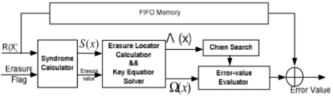
Fig. 1: The RS erasure decoding flow chart
Table 1 shows some a list of RS code applications and the finite field (FF) definition. Because of the different RS specific parameters, a cost efficient RS decoder that can support various applications has practical importance to
reduce the time-to-market and design costs. The design challenge is to realize a dedicated RS decoder that can accommodate different FF definition.
Table 1: List of applications with RS code as well as finite field definitions
Erasure is a type of error with the position information. A RS decoder with erasure correction will improve the performance in various systems. For erasure correction, a modified Berlekamp-Massey (BM) decoding algorithm without calculating Forney Syndrome is presented in [2]. Fig. 1 shows the RS erasure decoding flow chart which can be divided into four steps: 1) calculation of the syndrome S(x) and erasure value form the received codeword, 2) calculating the error and erasure locator polynomial Λ(x) and solving the key equation Ω(x) with BM algorithm or Euclidean algorithm, 3) search of error location, and 4) evaluation of error value.
In this paper, a universal architecture for RS error-and-erasure decoder is proposed. The universal RS architecture allows different code parameters in a single RS decoder, including codeword length, correctable error number, FF degree, and the corresponding primitive polynomial. The universal RS decoder has a flexible arithmetic unit based on the Montgomery multiplication algorithm [3]; therefore, all FF definitions with degrees less than a predefined one cab be fully covered.
Applications RS code specifications
LDC (248,216) RS code for GF(28), t=16
Blue-ray
DISC BIS (62,30) RS code for GF(28), t=16
Flash (526,518) RS code for GF(210), t=4
A,B (204, 188) RS code for GF(28), t=8
C (128,122) RS code for GF(27), t=3
ITU J.83
D (207,187) RS code for GF(28), t=10
DVB-T (204, 188) RS code for GF(28), t=8
Work supported by NSC and MOEA of Taiwan, R.O.C., under grant NSC 93-2200-E-009-027.
9-4
229
This paper is organized as follows. Section II presents the universal FF multiplier (UFFM). Each block of proposed universal architecture will be addressed in section III. The implementation results will be shown in section IV. Finally, section V concludes this universal RS decoder.
II. UNIVERSAL FINITE FIELD MULTIPLIER
The proposed UFFM is built on the Montgomery multiplication [3]. The Montgomery product of A and B can be expressed as (1).
*
ˆ( ) ( ) ( ) ( ) mod ( )
C x =A x B x k x p x (1)
The polynomial k*(x)=x-m is a constant element of
GF(qm) satisfying k(x)k*(x) =1 mod p(x) where k(x)=xm .
Therefore, before the Montgomery multiplication, A(x) or
B(x) must multiply by the correction factor k(x) to obtain the
correct result C(x).
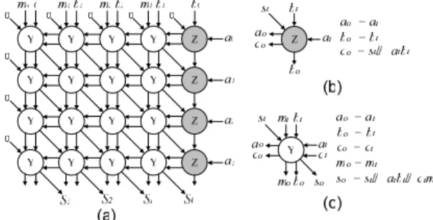
The Montgomery multiplier architecture for GF(2m) with
m≦4 is shown in Fig. 2. Fig. 2(a) illustrates the overall
architecture that comprises two functional units in Fig. 2(b) and Fig. 2(c). The signal ai and bi are the bits of two input
element A and B, mi is the i-th bit of the primitive
polynomial, and Si is the i-th output bits.
Fig. 2: Montgomery multiplier structure for GF(2m) while m≦4 As maximum field degree d has been implemented, any multiplication of GF(2m) with field degree less than d is
applicable.
III. UNIVERSAL RS DECODER ARCHITECTURE
The RS decoder consists of syndrome calculator, erasure locator polynomial expansion, key-equation solver, Chien-search and error-value evaluator, and a FF inversion table. All of these components will be detailed in the following subsections. Moreover, the area-effective approach for universal design will be presented.
A. Syndrome and Erasure Value Calculator
Let the R(x) be the received polynomial, and the syndromes can be obtained by substituting α1, α2, ...., α2t, that is, = R( ) for 1 ~ 2t m m i i S i
α
α
α
= (2),where αm is the correction factor for UFFM. Moreover, the
expression for syndrome calculation can be written in a series of recursive multiplications. In order to achieve cost efficient decoder, a constant UFFM (CUFFM) can be constructed by replacing one input of UFFM with a fixed finite field element. Because the Montgomery multiplication needs additional correction constant k(x)=αm, the substitution
can be modified to (3).
i i*n-1 i*n-2
n-1 n-2 0
( +(i- ))*n-1 ( +(i- ))*n-2
n-1 n-2 0
*n (i- ) *n-1 (i- ) (i- )
n-1 n-2 0 R( ) = R + R +....+ R = R + R a +...+ R = (...((R + R ) +..)..) + R m m m m m m m m m m m m m m m m m
α
α
α
α
α
α
α
α
α
α
α
α α
α
α
α
α
(3)Note that the α(i-m) is a CUFFM function.
Fig. 3 shows the universal syndrome and erasure value calculator with t≤8. The unit computes both the syndrome values and the erasure location vectors. When the erasure flag is valid, indicating the erasure occurs, the corresponding erasure value must be saved into registers. Furthermore, the syndromes have to be transmitted to next stage according to different correctable error and erasure number.
Fig. 3: The universal Syndrome and Erasure Value Calculator.
B. Erasure Locator Polynomial Expansion and Key Equation Solver
The error-erasure locator polynomial, or errata locator polynomial, can be obtained by initiating an inverse-free BM algorithm with the erasure locator polynomial [2]. Therefore, it is sufficient to consider only the erasure polynomial expansion. The modified BM erasure algorithm with erasure locator polynomial expansion is shown as follows [2]:
1. Initially set l=0, k=0, decode = 0, Λ(b)(x)=1,
Λ(a)(x)=0.
2. If (k<s and decode =0), set δ=1 and γ = Zk
3. Λ(c)(x) = γΛ(b)(x) + δ x Λ(a)(x) = (1+Z kx)Λ(x)
4. Set k=k+1 , If (k<s ) go to step 2, else set
decoder=1,
5. Compute the discrepancy 6. Compute Λ(c)(x) = γΛ(b)(x) + δ x Λ(a)(x) 7. If (δ ≠ 0 and 2l ≤ k – l) l = k - l, Λ(a)(x) = Λ(b)(x) 8. Λ(b)(x) = Λ(c)(x) 9. Set k=k+1. If (k < n – k), go step 5 10. Stop
k is the iteration number, s is the erasure number, Zk is the
erasure value provided by the syndrome stage, and Λ(x) is the errata locator polynomial. In this algorithm, if
decoder=0 initially and k < s, the erasure locator polynomial
will be calculated, and the signal decode will be asserted to start the BM algorithm. Due to the similarity of equations in steps 3 and 6, the erasure locator polynomial can be obtained regularly without additional UFFMs.
A decomposed BM architecture has proposed to reduce the circuit complexity significantly in [4]. As shown in Fig. 4, the decomposed architecture with 3 UFFMs has included the erasure locator polynomial expansion.
Fig. 4: The key equation block with erasure locator polynomial expansion.
C. Chien-search and Error Evaluator Block
The Chien search and error evaluator block can also be implemented with Horner’s rule. Since the area and critical path of CUFFM increase with the minus degree of α, the errata polynomial must be modified to avoid large minus degree. Assume the correctable erasure is 16, the modified errata polynomial form is expressed by:
-i -1 i -2 i -8 i 0 1 2 8 -9 i -10 i -16 i 9 10 16 -1 i -8 i 0 1 8 -1 i -2 i -8 i 9 10 16 -8 i ( ) = + ( ) + ( ) +....+ ( ) + ( ) + ( ) +....+ ( ) = + ( ) + ....+ ( ) + ( ){ ( ) + ( ) +....+ ( ) } α α α α α α α α α α α α
α
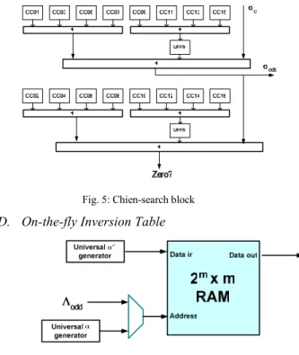
Λ Λ Λ Λ Λ Λ Λ Λ Λ Λ Λ Λ Λ Λ (4)Therefore, the maximum α minus degree is always 8, and the Chien search block can be implemented based on (4) as shown in Fig. 5.
Fig. 5: Chien-search block
D. On-the-fly Inversion Table
Fig. 6: On-the-flying inversion table
The implementation of Forney algorithm requires a universal FF inversion. There are two methods that realize the inverse operation, one is Fermat algorithm which replaces inversion with a series of square and multiply operations, and the other is the table look-up. Fermat algorithm requires many clock cycles to calculate the error value, leading to the requirement of larger FIFO buffer. Therefore, as shown in Fig. 6, the on-the-fly table look-up architecture, made up by 2m×m memory, universal α
generator and universal α−1 generator, is proposed.
According to different FF definition, the universal α
generator and α−1 generator update the FF elements and the
corresponding inverse value in the syndrome calculation. During error evaluation, the inversion table is available for Forney algorithm.
E. 8 ≤ t ≤ 16 Error-alone Correction
Since the proposed design supports the maximum 16 correctable erasures, it can be configured to correct at most 16 errors without any erasure. The syndrome is calculated twice with 2n clock cycles, assuming n is the block length. The syndromes S1~S16 will be calculated in the first n cycles.
If the first half of syndromes S1~S16 , calculated in the first n
cycles, are all zero, it is needless to calculate S17~S32, and the
follow-up decoding can be terminated, leading to lower calculation count. Otherwise, the syndromes S17~S32 should
be calculated.
IV. IMPLEMENTATION AND COMPARSION
Fig. 7 shows the proposed RS decoder architecture that can process any (n, t, m, p(x)) RS code with n≤ 255, t≤ 16, ( ) 0 l b j k j j
S
δ
− ==
∑
Λ
231and m≤ 8. The FIFO buffer is implemented by an 8k bits SRAM, and the FF inversion table uses a 2k bits SRAM. According to the RS_EN signal or syndrome value information, the block RS_Enable terminates the function blocks to save power consumption.
Fig. 7: Universal RS Decoder Block Diagram
Table 2: Comparison table for RS decoder with m≤8
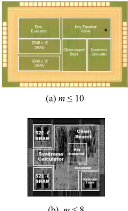
Table 2 shows a comparison of various RS decoders. Implemented by 0.13µm 1P8M technology, the proposed-I architecture for m≤10 can operate at 220MHz and has a throughput of 2.2Gb/s. The proposed-II architecture for m≤8 is designed with optimized CUFFM and can operate at 300MHz, achieving a 2.4Gb/s throughput. The proposed-I architecture using UFFM for constant multipliers has a larger gate count than the proposed-II. Consequently, CUFFM can significantly reduce the gate count of universal RS decoder. Fig. 8 shows the chip layouts of both proposed decoders. In Fig. 8(a), the core area is 0.78mm2 and the power consumption at 1.2V supply and 220MHz clock rate is 23.2mW. On the other hands, the chip in Fig. 8(b) is 0.36mm2 and the power consumption is 20.2mW, while working at 300MHz. Compared with other approaches, the proposed design has more flexibility and much higher decoding speed. Moreover, the cost efficient design in
proposed-II achieves a very flexible decoder as compared with [5].
(a) m ≤ 10
(b) m ≤ 8
Fig .8: CHIP layout of universal RS decoders
V. CONCLUSION
In this paper, the universal architecture for RS error-and erasure decoder is presented. The proposed architecture can accommodate variable codeword length, correctable errors, different finite field degrees, and different primitive polynomials. Furthermore, the proposed decoder can support erasure correction without increasing any finite field multipliers. This decoder is not only flexible but cost efficient as well.
REFERENCES
[1] Huai-Yi Hsu, and An-Yeu Wu, “VLSI design of a reconfigurable multi-mode Reed-Solomon codec for high-speed communication systems,” IEEE Asia-Pacific Conference, Page(s):359 – 362, 6-8 Aug, 2002.
[2] Jyh-Hong Jeng, and Trieu-Kien, Truong, “On Decoding of Both Errors and Erasures of a Reed-Solomon Code Using an Incersion-Free Berlekamp-Massey Algorithm,” IEEE Trans. on Commun., vol.47, no. 10, October, 1999.
[3] Chien-Ching Lin, Fuh-Ke Chang, Hsie-Chia Chang, and Chen-Yi Lee, ”An Universal VLSI Architecture for Bit-parallel computation in GF(2m),” IEEE Asia-Pacific Conference Circuits and Systems, 6-9 Dec, 2004.
[4] Hsie-Chia Chang, and Shung, C.B, “New serial architecture for the Berlekamp-Massey algorithm,” IEEE Trans. on Commun., Page(s):481 – 483, April, 1999.
[5] Jin-Chuan Huang, Ming Wu, and Ming-Der Shieh, Chien-Hsing Wu, “An area-efficient versatile Reed-Solomon decoder for ADSL,” Proc. IEEE Int. Conf. Circuits and Systems(ISCAS), Page(s):517 – 520, 30 May-2 June, 1999.
[6] A.G.M. Strollo, N.petra, D.De Caro, and E. Napoli “An Area-Efficient High-Speed Reed-Solomon Decoder in 0.25um CMOS,”
IEEE 30 th Eur. Solid State Circuits Conf. (ESSCIRC), 21-23
Sept. 2004
[6] [1] [5] Proposed-I Proposed-II
Mode Single Variable (n, t) Universal (n, t, m) p(x) Universal (n, t, m) p(x) Universal (n, t, m) p(x) m 8 8 1~8 1 ~10 1 ~ 8 Erasure No No No ≤ 16 ≤ 16 t 8 1 ~ 8 1 ~ 8 1~ 8 1 ~ 16 Technology 0.25µm 0.35µm 0.25µm 0.13µm 0.13µm Data rate bits/s 1.6G 800 M 48 M (serial) 2.2G (parallel) 2.4 G (parallel) Gate count 21K 34K 44K 75K + 35K RAM 39K + 15K RAM 232