應用隔振系統降低船舶振動之研究
On the vibration reduction of ships using vibration isolation systems
計畫編號:NSC 89-2611-E-002-027
執行期限:88 年 8 月 1 日 至 89 年 7 月 31 日
主持人:薛文証
共同主持人:陳重盛
計畫參與人員:王志星、莊依傑、吳昭興、蔡懿凱
執行單位:臺灣大學造船及海洋工程學系
一、中文摘要 本計畫主要研究隔振系統在降低激振 源對船舶結構產生振動之作用,隔振系統 已廣泛應用在船舶之減振設計上,本研究 首先分析激振源、隔振系統與結構之間之 振動能傳遞情況,建立三者間振動能之交 制模式,然後以一典型均質串接 Kelvin 阻 尼為例,利用已建立之交制模式,探討其 對振動傳輸率之影響。 關鍵詞:隔振系統、船舶振動1. Abstr act
Study of the effect of isolators for reducing the vibration transmissibility from engine to ship structure is presented. The interaction of the vibration among the excitation source, isolator, and foundation is studied. Finally, an isolator modeled on a series connection of a MDOF mechanical system and an SDOF model of a flexible foundation are examined to illustrate the advantage of this method in practical.
Keywor ds: Isolator, Ship vibration
2. Intr oduction
The vibration isolator is usually installed between a dynamic system and an excitation source to protect the system from undesired vibration. One purpose of using the isolators is to reduce the acting force
transmitted from the excitation force
generated by an unbalanced revolution of the machine, called a force isolation system. The design objective is to obtain a lower force transmissibility for the former system and a velocity (or displacement acceleration) transmissibility for the latter system. Since a dynamic coupling among the machine, isolator and foundation exists, all of the
components in the total system are
considered to be simultaneous in the analysis, which may work well when the configuration of the isolator is very simply [1]. However, certain commonly used isolators, such as natural rubber or rubberlike material, are rationally modeled in practice as a series connected multi-degree-of-freedom (MDOF) dynamic system [2]. For these isolators, the computation is quite complex[3-5]. In fact, the isolator generally designed under the given condition of the machine and the foundation is fixed. If the interaction between the machine and isolator as well as the isolator and foundation can be known, the isolation system would be analyzed and designed more efficiently.
In this article, a closed form solution of the force and velocity transmissibility of the isolation systems is calculated. Finally, an isolator with a uniform multiple layered structure and a single-degree-of-freedom (SDOF) flexible foundation are examined.
3. Results
When an isolator is used to support a rotary machine with a periodical unbalanced
force on the foundation as shown in Fig. 1, this system can be modeled as a connection of three parts - a mass for the machine, a dynamic system for the isolator and a foundation. Assuming a periodical excitation force with frequency ω, the steady state response of the force ft(t) and velocity vm(t)
and vt(t) should be also periodical and with
the same frequency, but having different phase angles. Let the excitation be given as the real part of fext( )t = F eext j tω , where Fext
is the complex amplitude with units of force containing information about the phase angle.
j is defined by j=(-1)1/2. Based on Newton’s law, the relationships of ft(t), vm(t) and vt(t)
may also be expressed as
Ft =Fext − j m Vω m t, Vm=Vt (1, 2) where Fm, Vm and Vt are the complex
amplitude of ft(t), vm(t) and vt(t). These Fext,
Vt, Ft and Vm are defined as the power flow
variables with respect to the dynamic system of the machine model. If Fext and Vt, are
selected as the input variables, Ft and Vm
should be a function of the input variables defined as the output variables.
Assume the isolator is modeled as a linear dynamic system. The steady state response of the velocity and force at the top and bottom of the system are also periodical with the same frequency as an excitation. If the complex amplitude of the acting force on the top Ft and the velocity of the bottom of
the isolator Vb are selected as the input
variables, the complex amplitude of the acting force on the bottom Fb and the
velocity of the top of the isolator Vt can be
expressed as
Fb =TRf t b t, , F +Z Vb b, (3)
Vt =Y Ft t +TRv b t b, ,V (4)
where TRf,t,b is the complex force
transmissibility of the isolator from the top to the bottom and TRv,b,t is the complex velocity
transmissibility of the isolator from the bottom to the top of the isolator defined as
TR F F f t b b t Vb , , = =0 , TR V V v b t t b Ft , , = =0 (5,6)
Zb and Yt are the impedance and the mobility
of the isolator at the bottom and the top defined as Z F V b b b Ft = =0 , Y V F t t t Vb = =0 (7, 8)
For the first case, Case I, a system with a rigid foundation is considered. Thus, zero displacement and velocity response should be maintained. The boundary conditions are given by
Fd = Fb, Vb =Vd =0 (9,10) where Fd and Vd are the complex amplitude
of the reaction force and velocity of the foundation. The force transmissibility from
Fext to Fb, TR1,m,b, leads to TR TR j m Y m b f t b m t 1 1 , , , , = + ω (11)
If the foundation is flexible with mobility Yd,
called Case II, the boundary condition in Eq. (14) is changed to
Vb =Y Fd b (12)
According to Eqs. (3), (4), (9) and (12), the force transmissibility TR2,m,b can be
calculated as [6] ) ) ( 1 /( ,, ,, , , , , 2 d b d b t t b v b t f d t m b t f b m Y Z Y Z Y TR TR Y Y m j TR TR − − + + = ω (13)
Thus, the force transmissibility from Fext to
Fd should be equal to Eq. (11). The
transmissibility from Fext to Vb is
YdTR2,m,b.
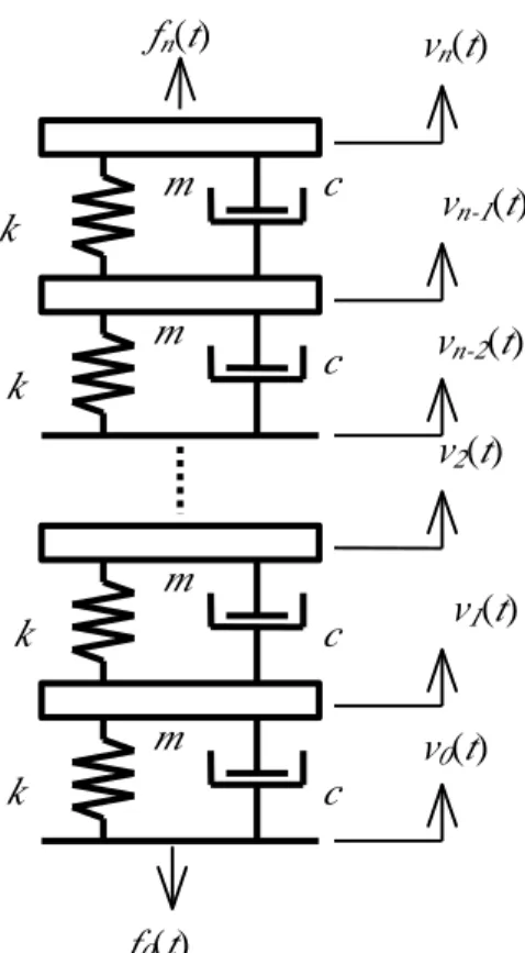
An isolator modeled as an n series
connection of identical mechanical
subsystems as illustrated in Fig. 2 is considered in the example. For each layer,
the subsystem includes one mass series to a parallel connection of a spring and a damper. If the force and velocity of each component in the ith subsystem from the base are
defined as Fig. 2, the dynamic equations expressed by the complex amplitude of these force and velocity variables are given by
Fi−1= Fi − j mVω i, (14)
(
/ω)
/ 1 1 F c kj V Vi = i− + i− − (15)According to Eqs. (14) and (15), the force complex transmissibility of the isolator leads to [6] 1 0 , , ( ( ,2 ) ) − =
∑
+ = n i i b t f C n i i L TR (16)Where L=−ω2m/(jωc+k). The velocity complex transmissibility TRv,b,t is equal to the
force complex transmissibility TRf,t,b . The
driving mobility at the top and the driving impedance at the bottom of the isolator lead to [6]
(
/)
( ( ,2 ) ) ) 1 2 , ( 0 1 0∑
∑
= − = + − + + = n i i n i i t L i i n C kj c L i i n C Y ω (17)∑
∑
= − = + + + − = n i i n i i b L i i n C L i i n C m j Z 0 1 0 ) 2 , ( ) 1 2 , ( ω (18)If the flexible foundation of Case II is modeled as an SDOF mass-spring-dashpot component as illustrated in Fig. 3, the mobility of the foundation leads to
(
)
Y c j m k d d d d = + − ω ω ω2 (19)4. Conclusions
In this study, the interaction between the machine and isolator as well as the isolator and foundation were illustrated. Moreover, the solutions of the force and
velocity transmissibility were calculated. The analytical solution of the three cases of the isolation systems, including the force isolation systems with rigid and flexible foundations subject to a periodical excitation from the machine and the velocity isolation system subject to foundation vibrations, have been investigated. Finally, an MDOF series mechanical model of the isolator and an SDOG mechanical model of the foundation were examined.
5. Refer ences
1. J. C. Snowdon 1986 Vibration and
Shock in Damped Mechanical Systems.
New York: John Wiley and Sons.
2. C. Ianniello and L. Maffei 1982 J. Acoust. Soc. Am. 72, 482. A Lumped
Parameter Model for the Iterative Analysis of Cylinderlike Antivibration Mounts.
3. C. T.Malloy 1957 J. Acoust. Soc. Am. 25,
842. Use of four-pole parameters in Vibration analysis.
4. M. L. Munjal 1975 J. Sound Vib. 39,
247-263. A Rational Synthesis of Vibration Isolators.
5. S. A. Paipetis and A. F. Vakakis 1985 J. Sound Vib. 98 13-23. A Method for
Unidirectional Vibration Isolators with Many Degrees of Freedom.
6. W. J. Hsueh 1998 J. Sound Vib. 216,
399-412. Analysis of vibration isolation systems using a graph model.
6. Figur es
Fig. 1 (a) physical model and (b)variables definition of an isolation system
m k c vn(t) m k c vn-1(t) vn-2(t) v2(t) m k c m k c v1(t) v0(t) fn(t) f0(t)
Fig. 2 Mechanical model of the MDOF isolator
Fig. 3 (a) mechanical model, and (b) power-flow model of the SDOF foundation
kd cd md vb(t) fb(t) fd(t) (a) Isolator fext(t) Machine Foundation Isolator fext(t) vd(t) (b) mm ft(t) fb(t) vb(t) vt(t) vm(t) Foundation
5