行政院國家科學委員會補助專題研究計畫成果報告
※※※※※※※※※※※※※※※※※※※※※※※※※
※ ※
※ 金屬粉末射出成形零件的尺寸穩定性研究 ※
※ ※
※※※※※※※※※※※※※※※※※※※※※※※※※
計畫類別:□個別型計畫 □整合型計畫
計畫編號:NSC 89-2216-E-002-022
執行期間: 88 年 08 月 01 日 至 89 年 07 月 31 日
計畫主持人:黃坤祥 教授
本成果報告包括以下應繳交之附件:
□赴國外出差或研習心得報告一份
□赴大陸地區出差或研習心得報告一份
□出席國際學術會議心得報告及發表之論文各一份
□國際合作研究計畫國外研究報告書一份
執行單位:國立台灣大學材料科學與工程學研究所
中 華 民 國 89 年 10 月 31 日金屬粉末射出成形零件的尺寸穩定性研究
The Dimensional Control of Powder Injection Molded Compacts 計畫編號:NSC 89-2216-E-002-022 計畫期限:88 年 08 月 01 日至 89 年 07 月 31 日 主持人:黃坤祥 國立台灣大學材料科學與工程學研究所教授 計畫參與人員:胡紹中 國立臺灣大學材料科學與工程學研究所博士生 1、中文摘要 粉末射出成形製程對具複雜形狀之零 件具有極佳的成形能力,但由於整個製程 之尺寸收縮高達 12-20%,其製品的尺寸穩 定性不如傳統粉末冶金容易控制。在射出 成形製程中,每一個步驟對產品的最終尺 寸穩定性皆有影響,但以脫脂(包括溶劑脫 脂與熱脫脂)及燒結步驟最為重要。 本計畫延續申請人之前的研究,對於 射出件在熱脫脂與燒結過程中的尺寸變化 情形與變形行為作更深入的探討,特別是 在黏結劑含量及燒結方面。實驗利用雷射 膨脹儀及熱膨脹儀分析溶劑脫脂、熱脫脂 與燒結過程中試片的尺寸變化,結果顯示 7%之黏結劑較 6.5%及 8%者為佳,而燒結時 經過相變態者較差,此外,試片若厚薄不 均將造成變形,主黏結劑未達 30%、脫脂溫 度超過 45℃時其尺寸穩定均不佳。熱脫脂 時在氫氣氣氛下易因滲碳而變形,宜採低 升溫速率、真空或惰性氣體。 關鍵詞:粉末射出成形、尺寸穩定性、熱 脫脂、in-situ 脫脂行為、變形 2、Abstr act
The major advantage of the powder injection molding process is its ability to produce net or near net shaped components with good mechanical properties. However, the dimensional control of PIM compacts has been the most critical hindrances of the further growth of this technology. This problem occurs mostly during the debinding and sintering processes. This study uses the laser and thermal dilatometers to analyze the
in-situ length change during debinding and
sintering. The emphasis was on the binder content and processing parameters. The results show that the 7% binder was the best compared to the 6.5% and the 8% binder systems. The major binder content should be no less than 30% when the repeatability of the dimension is required. The uneven cross-section thickness in the compact, high solvent debinding temperature greater than 45℃, and hydrogen atmosphere were also shown to be the causes of distortion. With these data, the mechanism of the expansion and distortion are analyzed and suggestion on the process and the required material
characteristics are presented.
Keywor ds:powder injection molding,
defects, distortion, dimensional control
3、Background
Powder injection molding process has
been widely accepted to fabricate structural parts with complex shapes. However, owing to the large amount of shrinkage, 12 to 20%, accumulated from molding, debinding, to sintering, the dimensional control is difficult and has become one of the most critical hindrances for the further growth of this technology. Thus, how to improve the tolerance of PIM parts has become an important subject in recent PIM studies. One of the approaches was to use non-spherical water atomized powders. The
irregular shape gives more mechanical locking, more interparticle friction, less powder rearrangement and powder sliding during debinding and sintering.[1-4] The binder design also plays an important role. Examples are those with polyacetal as the backbone binders which showed improved dimensional controls.[5,6] The processing parameters have also been examined. Lin and German showed that the solvent debinding temperature was critical.[7] Too high a temperature will cause slumping while too low a temperature will cause cracking. Lin and Hwang measured the in-situ length
changes during solvent debinding using a laser dilatometer.[8] They showed that high backbone binder content, high debinding temperature and low molecular weight solvent will increase the amount of swelling which is not favored during solvent debinding. Hu and Hwang also indicated that uneven cross-section thickness of the parts will also affect the shape retention capability.[9] The thermal debindng was also recognized to be critical in the dimensional control of PIM parts. Miura and Takamori indicated that less deformation was noticed by debinding in vacuum and using slow heating rates, than those use nitrogen and high heating rates.[4] They also compared the effect of binder content, 8.5, 9.0, 10.0, and 11.0wt%, and noticed that the 8.5wt% binder system has the best shape retention capability. On the sintering side, Shoales and German measured the in-situ strength of
compacts during sintering and provides guidelines of the thermal cycle design.[10,11]
It has been generally believed that as
the solid content increases, the interparticle friction increases and help retain the complex shape of PIM parts. However, few reports to date have been reported about the details on the dimensional stability through solvent debinding, thermal debinding, and sintering.[4] Thus, the purpose of this study was to investigate the effect of material characteristics and processing parameters on the deformation of compacts, with an emphasis on the effect of metal powder content.
4、Results and Discussion
4.1 Molding: Figure 1 shows the apparent viscosity of three systems containing 6.5, 7.0, and 8.0wt% binder, respectively. The data were measured with a fixed shear rate at 1000/s. The results shows that the viscosity decreases as the binder content increases. Base on this data, the barrel and nozzle temperatures in the molding machine were selected, as shown in Table 1, for the three systems, respectively, so that they all have similar viscosity. This will alleviate the effect of molding and the results of dimensional control can thus be attributed only to debinding and sintering.
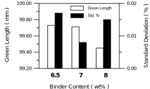
Figure 2 and Figure 3 show, respectively, the green length and green density of the three systems investigated. The 7.0% binder system gave the smallest standard deviation on both length and density. The high binder content caused more shrinkage after cooling in the mold due to the large amount of shrinkage of the paraffin wax in the binder. As the binder content decreases, the flow could still be poorer for the 100mm long specimen made in this study. This is possible because the thermal
conductivity is better when the metal powder content increases, which cooled the material faster and increased the viscosity despite of the equivalent apparent viscosity measure by the rheometer.
Figure 4 shows the green strength of the three systems. All three systems have higher strength than the pure binder and the pure metal powder which has the same solid content of 64v/o. However, when these specimens were placed in the thermal-mechanical analyzer, the 6.5% binder system had the least distortion as shown in Figure 5. This suggests that the binder provides the main strength of the compacts at room temperature. But, when the temperature is greater than the melting point of the binder, which is 98℃, the greater amount of the binder, the lower strength of the compact. 4.2 Debinding: The effect of the binder content on the length changes of the compact during solvent debinding is illustrated in Figure 6. As the binder content increased from 6.5% to 8.0%, the amount of swelling increased. Figure 7 illustrates the amount of sagging after 90% of the soluble binder had been removed. The 100mm-long specimens were supported by two ridges with a span of 60mm. The results show that as the temperature increased, the amount of sagging increased. Moreover, the slope of these curves increased when the temperature was over 50℃, which is near the melting point of the paraffin wax. It was surprising that the amount of sagging was the largest with 8.0% binder. Since 90% of the binder had been removed, this means that the backbone binder contributes most to the strength of the specimen during solvent debinding, not the
metal powder content or the interparticle friction.
Figure 8 illustrates the length changes of the three specimens with different binder content during thermal debinding. No significant difference was noticed. Figure 9 shows the amount of deflection of the specimens which were supported at one end only and with overhung extensions. The curves show that the amount of deflection increased as the extended length and the binder content increased. The specimen with 8.0% binder broke at 400x10-6
N⋅m, or at a shear stress of 60kPa. The 6.5% binder specimen failed at 89kPa. All these specimens failed below 360 ℃ , which is lower than the starting temperature for binder decomposition. Thus, the failure is caused by the softening of the specimen. In this regard, 6.5% binder system is favored.
4.3 Sintering: Figure 10 shows the dimensional stability of the compacts through molding, solvent debinding, thermal debinding, and sintering. The standard deviation indicates that sintering plays the most important role in the dimensional control. The 7.0% binder specimens were the best compared to the 6.5 and 8.0% binder systems. The high solid content system, though provides high interparticle friction which help hold the compact dimensions. The poorer molding performance seems to indicate that the high solid content could have impaired the moldability. This could be because the higher molding temperature results in bigger amount of shrinkage. Moreover, as the material flow into the die and cooled down, the 6.5% binder system will have higher viscosity and cause less
homogeneous green density.
The effect of the phase transformation was also investigated. Figure 11 shows that when the specimen was sintered in the alpha phase at 870 ℃ , its dimensions are more stable, compared to that sintered at 950℃. This indicates that the volume changes during the phase transformation hurts the dimensional control. Thus, how to avoid abrupt phase changes is worthwhile for further investigation. 5. 計畫成果自評 本計畫最主要之發現為對於粉末射出 成形零件的尺寸穩定性而言,高固含量不 見得是最佳者,且相變態也是一個重要的 因素。此為前人未曾報導過者。本研究與 預期成果相當接近。此成果之一部份並已 發表在今年之 Powder Metallurgy 及 P/M Sci. & Tech. Briefs. 及中國材料學會 1999 年年會論文集中。
參考文獻
1. R. H. Hershberger et.al., Adv. Powder Metall. Part. Mater., 1995, 6, MPIF, pp.
89-94.
2. K. M. Kulkarni, Intl. J. Powder Metall.,
1997, 33(4), pp. 29-41.
3. C. M. Kipphut and R. M. German, Int. J. Powder Metall., 1991, 27(2), pp. 117-124.
4. R. Miura and S. Takamori, Powder Injection Molding Symposium, 1992,
MPIF, pp. 359-370.
5. T. J. Weaver, K. F. Hens, and R. M.
German, Adv. Powder Metall. Part. Mater.,
1995, 6, MPIF, pp. 71-78.
6. Y. Kankawa, S. Takamori, and N. Tsukamoto, Powder Injection Molding Technologies, 1998, pp. 115-124.
7. S. T. Lin and R. M. German, Powder Metall. Int., 1989, 21(5), pp. 19-24.
8. H. K. Lin and K. S. Hwang, Acta Mater.,
1998, 46(12), pp. 4303-4309.
9. S. C. Hu and K. S. Hwang, Met. Mat. and Mat. Trans. A, 2000, 31A, pp. 1473-1478. 10. G. A. Shoales and R. M. German, Metall.
Trans., 1999, 30A, pp. 465-470.
11. G. A. Shoales and R. M. German, Metall. Trans., 1999, 29A, pp. 1257-1263.
Table 1 The molding parameters of the three systems containing 6.5, 7.0, and 8.0wt% binders.
Binder Content, wt% 6.5 7.0 8.0 ---nozzle temp., ℃ 150 140 120 barrel temp., ℃ 153/155/145 143/145/135 123/125/115 mold temp., ℃ 45 35 35 ---100 110 120 130 140 150 160 170 180 Temperature ( ℃ ) 1E+1 1E+2 A p p a re n t V is c o s it y ( P a *s e c ) 6.5% 7% 8% CIP-S-1641 share rate=1000/sec
Figure 1 The apparent viscosity of the feedstock decreases as the binder content increases.
Binder Content ( wt% ) 99.20 99.40 99.60 99.80 100.00 G re e n L e n g th ( m m ) 0.00 0.01 0.02 S ta n d a rd D e v ia ti o n ( % ) Green Length Std. % 6.5 7 8
Figure 2 The 7.0wt% binder system gives smaller standard deviation on the green length than the 6.5 and 8.0% binder systems.
Binder Content ( wt% ) 4.60 4.80 5.00 5.20 G re e n D e n s it y ( g /c m ) 0.00 0.02 0.04 0.06 S ta n d a rd D e v ia ti o n ( % ) 3 Green Density Std. % 6.5 7 8
Binder Content ( wt% ) 0 4 8 12 16 20 G re e n S tr e n g th ( M P a ) 0.4 13.7 14.6 15.2 6.2 0 6.5 7 8 100
Figure 4 The 8.0wt% binder system gives the highest strength, even better than the pure binder and the pure metal powder with 64v/o density.
0 20 40 60 80 100 120 140 160 180 Temperature ( ℃ ) -2000 -1600 -1200 -800 -400 0 D im e n s io n C h a n g e ( m ) CIP-S-1641 40LDPE:55PW:5SA As-Molded 5℃ /min H 2mm thick disc 2 6.5% 7% 8% µ
Figure 5 The depth of the indentation by the push-rod for the three material systems as they are heated to 180℃.The 6.5% binder system has the least dimensional change.
0 3 6 9 12 15 18 21 Time ( ks ) 0.00 0.20 0.40 0.60 L e n g th C h a n g e ( % ) 8 % 7% 6.5% CIP-S-1641 Heptane 40℃
Figure 6 The amount of expansion increases with the increase of the binder content.
25 30 35 40 45 50 55 60 Temperature( ℃ ) 0 400 800 1200 1600 2000 S a g g in g D is ta n c e ( m ) 6.5% Binder 7 % Binder 8 % Binder CIP-S-1641 40LDPE:55PW:5SA Heptane µ
Figure 7 The effects of the solvent debinding temperature and the binder content on the sagging distance of compacts after removing 90% of the soluble binder.
0 100 200 300 400 500 600 700 Temperature ( ℃ ) -1.50 -1.00 -0.50 0.00 D im e n s io n a l C h a n g e ( % ) 5℃ /min 650℃ H 0% 6.5% 7% 8% 2
Figure 8 Dilatometer curves of specimens containing 0, 6.5, 7.0, and 8.0% binder. 10 15 20 25 30 35 40 Extended Length ( mm ) 0 2 4 6 8 10 12 D e fl e c ti o n ( m m ) CIP-S-16415℃ /min 700℃ , 1 hour H2 8% binder 7% binder 6.5% binder : failure point
Tensile Bending Strength ( kPa ) 20 40 60 80 100
Figure 9 The amount of deflection of the specimens with Different binder content during thermal debinding.
0.00 0.02 0.04 0.06 0.08 0.10 S ta n d a rd D iv ia ti o n ( % ) CIP-S-1641 Binder Content 6.5% 7 % 8 % Molded S-D T-D Sintered S-D:Solvent Debound T-D:Thermal Debound
Figure 10 The dimensional stability of specimens containing 6.5, 7.0, and 8.0 % binder through molding, solvent debinding, thermal debinding, and sintering.
10 11 12 13 14 15 S h ri n k a g e ( % ) 0.00 0.01 0.02 0.03 0.04 0.05 S ta n d a rd D e v ia ti o n ( % ) 1641-7B H2 A B Length Standard deviation
Figure 11 The dimensional control of compacts sintered at 870℃ in the alpha phase is better than those sintered at 950℃ indicating the effect of the phase change.