MLP INTERPOLATION FOR DIGITAL IMAGE
PROCESSING USING WAVELET TRANSFORM*
Yu-Len Huang and Ruey-Feng Chang
Department of Computer Science and Information Engineering
National Chung Cheng University
Chiayi, Taiwan 62107, R.O.C
ABSTRACT
In this paper, we present nonlinear interpolation schemes for image resolution enhancement. The Multilayer perceptron (MLP) interpolation schemes based on the wavelet transform and subband filtering are proposed. Because estimating each sub-image signal is more effective than estimating the whole image signal, pixels in the low-resolution image are used as input signal of the MLP to estimate all of the wavelet sub-image of the corresponding high-resolution image. The image of increased resolution is finally produced by the synthesis procedure of wavelet transform. As compared with other popular methods, the results show that the improvement is remarkable. The detail simulation results of interpolated images and image sequences can be found in web page: http://www.cs.ccu.edu.tw/~hyl/wmi/.
1.
INTRODUCTION
Interpolation is used extensively in digital image processing to magnify images and correct spatial distortions. Image interpolation is used for several different purposes such as image resolution enhancement, multi-resolution pyramidal compressing, position computing for rotated image pixels, and etc. In the past years, many linear and nonlinear image interpolation techniques have been proposed. In the linear methods, the nearest-neighbor, bilinear, cubic B-spline, and cubic convolution interpolation methods are widely used to increase resolution of images. Both the nearest-neighbor and bilinear methods provide the interpolation function with a very small computation time, but they will cause conspicuous blocking artifacts. The cubic interpolation algorithms can reduce the blocking effects, but it always blurred the reconstructed image and produced some ringing effects in the edge regions. With the rapid increase in available computing power, the nonlinear techniques for image interpolation have received increasing attention recently [1-3]. Because the characteristics of the edges in a digital image can be reserved for many scales of resolution and the edges are always important for human vision, most of the nonlinear interpolation algorithms tend to focus on the edge information. In these papers, the local edge structure of the original image is preserved to prevent the blurring and blocking effects in the interpolated image. The proposed methods determine the edge localization or classification by exploiting an edge fitting technique within small overlapping windows of the original image. We notice that the interpolation schemes utilize different reconstruction rules that are decided by the edge pattern. However, if the window size is larger than 3Y3 or the edges in
a window are irregular, the implementation will become complex and inefficient, and then the schemes will product poor performance for image resolution enhancement. Thus, we desire to develop simple and flexible interpolation scheme to solve the problem.
The wavelet transform has been identified as an effective tool for time-frequency representation of signals [4-6]. It can decompose a digital image into some frequency sub-images, each represented with proportional frequency resolution. The resulting band-pass representation provides that the solution space of many image-processing problems can be decomposed into its lower frequency subspace and higher frequency subspaces. In this paper, in order to reduce the complexity of interpolation problem, we have developed an accurate method of low implementation complexity that is well suited for increasing resolution of images based on wavelet transform. Multilayer perceptrons (MLPs), an important class of neural networks (NN), have been found to be particularly effective for problems that can make use of supervised training. The MLP is enabled to extract higher-order statistics by adding one or more hidden layers. This model has become extremely popular for both classification and prediction. Many details on its implementation and uses are given in [7-8]. In this paper, we employ the MLP model as the predictor for both of the spatial and frequency signals to increase resolution of image.
The rest of this paper is organized as follows. Section 2 reviews the main features of wavelet transform and MLPs. Section 3 describes the construction of the spatial MLP interpolation model. Further, Section 4 presents the structure of the MLP interpolation scheme based on wavelet transform. Experimental results are given in Section 5. Finally, conclusions are drawn in Section 6.
2.
WAVELETS AND MLP
For fast computation, the bi-orthogonal wavelet transform is used in this work. The bi-orthogonal wavelet filters require few tapes, unlike standard subband QMF methods. The detail properties and construction of regular bi-orthogonal wavelet transform are described in [4]. Furthermore, the MLP, which is the standard neural network model, is also performed in this paper. In general, the error back-propagation algorithm reported in [9-10] is the most widely used and a powerful learning algorithm for the MLP. For completeness, we review the concepts of the bi-orthogonal wavelet analysis and the MLP model as follows.
2.1
Bi-orthogonal Wavelet Transform
In practice, the wavelet transform is implemented with a perfect reconstruction filter bank. The idea is to decompose the image signals into sub-images corresponding to different frequency
*This work was supported by the National Science Council, Taiwan, Republic of China, under Grant NSC-87-2213-E-194-025.
contents. Let H( ) and G( ) are the low-pass and high-pass filters of a perfect reconstruction filter bank, respectively. In one-dimensional (1-D) case with one level decomposition, the input signal x[n] is filtered by h[n] and g[n]. Then, the resulted sub-image signals are down-sampled by a factor of two. In the two-dimensional (2-D) case, the 1-D decomposition procedure is first applied to each row of an image signal. The decomposition results in two intermediate sub-images. Then the same procedure is applied to each column of the intermediate sub-images. For a one level decomposition, this results in four sub-images LL, LH, HL, and HH. In hierarchical wavelet decomposition, the sub-image LL is further decomposed into other four sub-images. Similarly, the reconstruction for the image is done one level at a time by using the 1-D reconstruction procedure.
2.2
Multilayer perceptron (MLP)
A MLP model contains one or more hidden layers and the function of neurons in the hidden layer is to arbitrate between the input and the output of neural network. The input feature vector is fed into the source nodes in the input layer of the neural network at first. The neurons of the input layer constitute the input signals applied to the neurons of the hidden layer. The output signals of the hidden layer can be used as inputs to the next hidden layer or the output layer. Finally, the output layer products the output results and terminates the neural computing process.
Among the algorithms used to design the MLPs, the back-propagation algorithm is the most popular one. There are two different phases, the forward phase and the backward phase in the back-propagation algorithm. In the forward phase, the input signals are computed and passed through the neural network layer by layer. Then, the neurons in output layer product the output signals of the neural network. In this time, the error signals can be generated by comparing the output response of the neural network with the desired response. In the backward phase of the back-propagation algorithm, some free parameters are able to be adjusted by referring the error signals. This work can be used to minimize the distortion of the MLP. In this work, the back-propagation learning algorithm is iteratively executed for the training set and then products the synaptic weight vectors. By using the final synaptic weight vectors into the MLP, it is used to predict the unknown pixels in our image interpolation schemes.
3.
ADAPTIVE MLP INTERPOLATION
In this section, we introduce the first new interpolation scheme, i.e. spatial adaptive MLP interpolation scheme (SAMI), which can be used to increase the image resolution by a factor of two in the spatial domain. The MLP model is used to interpolate the digital images as a nonlinear predictor. In order to preserve the fine regions of the reconstructed image, our scheme contains a simple classification algorithm and neural network predictors to produce the unknown pixels and avoid the image burring effects. At first, the Sobel operators are used to detect linear edges for a low-resolution image, resulting in a detected edge image. The information of the edge representation is used as the input of overlapping window classifier. We classify a high-resolution window into two cases based on the standard deviation σ of the low-resolution edge image window. The standard deviation is
used to determine the case for each high-resolution window by the classification rules that described as follows.
Case 0 (Smooth region window): if σ≤ T.
Case 1 (Non-smooth region window): if σ > T.
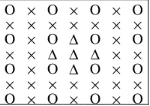
where T is the predefined threshold. Based the simple classification algorithm, the SAMI scheme uses two MLP modules to estimate the unknown pixels in the high-resolution window. O × O × O × O × × × × × × × O × O ∆ O × O × × ∆ ∆ ∆ × × O × O ∆ O × O × × × × × × × O × O × O × O
Figure 1. The input and output pixels in a window with
size 7 × 7 for SAMI scheme. The sample locations denoted O, ×, and ∆ are the input, unknown, and output signals, respectively.
An example of interpolation window with size 7 × 7 is shown in Fig. 1. The MLP utilizes the known pixels within the high-resolution image to estimate gray levels of unknown pixels. After each high-resolution window has been processed, five unknown pixels will be interpolated. Except the central pixel of the overlapping windows, all of the unknown pixels in the high-resolution image will be calculated twice. For these pixels, the average of the two predicted gray levels is used as the final result. Moreover, using the bilinear interpolation operator can produce the unknown pixels located on the fringes of the high-resolution image. In the computer simulation, the SAMI achieves a limited success in improving the interpolation quality of natural image. We found the reason is that the natural image signals are nonstationary in spatial domain. There are two ways to improve the performance of the SAMI scheme, adopting the more accurate classification algorithm in the interpolation scheme or turning to interpolate the low-resolution image by using a band limited transformation. Because of the implementation complexity must be increased heavily when the classification algorithm becomes complex. Hence, in order to reduce the computation time, we developed the second neural network interpolation scheme that exploits the wavelet transform for image resolution enhancement.
4.
MLP INTERPOLATION USING
WAVELET TRANSFORM
By using the wavelet transform, the solution space of the interpolation problem can be decomposed into its low-frequency subspace and higher-low-frequency subspaces. Based on this idea, we develop the wavelet MLP interpolation (WMI) scheme that utilizes the property of dividing image spectrum to augment the interpolation accuracy of the neural networks. WMI does not use the traditional edge classification algorithm to enhance or reserve the high-frequency portion of interpolated image. In general, the 2-D wavelet transform splits the nonstationary image spectrum into four more stationary sub-images LL, LH, HL, and HH. Then, only the lowest frequency sub-image LL is further split into four smaller sub-images. In this paper, we consider the one level analysis/synthesis
procedure of wavelet transform for increasing the image resolution by a factor of two.
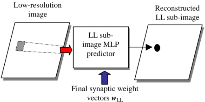
As shown in Fig. 2, the signals in the overlapping windows of low-resolution image is used as input vector of neural network predictor, and then the output signal of reconstructed wavelet sub-image LL is generated. The same structure is also employed for the reconstruction of the higher-frequency sub-images. Also, all of these four modules use the MLP to estimate the sub-image signals. The final synaptic weight vectors (wLL, wLH, wHL, and wHH) for the corresponding wavelet sub-image predictor is
generated by the back-propagation learning algorithm with the images in training set and its sub-image signals that generated by the wavelet analysis procedure. The MLP predictors utilize the low-resolution image signals to estimate the signals in the wavelet sub-images of high-resolution image. Finally, the estimated wavelet sub-images are used to compose the interpolated high-resolution image through the 2-D wavelet synthesis operator. The interpolation algorithm for an M × N low-resolution image with the desired increasing resolution factor by Z is described as follows,
Step 1. Initially, store the evaluated final synaptic weight vectors into the corresponding MLP predictor. Set the width m and height n of high-resolution image; as m ← 2 × M and n ← 2 × N. Set i ← 1.
Step 2. The MLP with the synaptic weight vectors wLL is used
to estimate all of the signals in the LL sub-image of the high-resolution image. The signals in the low-resolution image are used as the input vector of MLP. Similarly, the LH, HL, and HH sub-images can be produced by the corresponding sub-image MLP predictors, respectively.
Step 3. Boundary pixels of the LL sub-image that are incalculable for the LL sub-image predictor are stored the gray level in low-resolution image at corresponding position. The incalculable signals in the estimated LH, HL, and HH sub-images are set 0.
Step 4. Use the 2-D wavelet synthesis procedure to compose the estimated wavelet sub-images and result in an m ×
n interpolated image with increasing the original
resolution by factor 2i.
Step 5. If Z / 2i > 1, then set i ← i + 1; set m ← 2 × m and n ← 2 × n; go to step 2.
In the WMI scheme, the neural network predictors can be adapted to the statistical properties of each wavelet sub-image, and hence estimating each stationary sub-image signals is more efficient than estimating the whole nonstaionary spatial signals. The above algorithm is always practical even if the edges in image are complex or irregular. Furthermore, the proposed scheme supports a progressive interpolation processing. The reconstructed high-resolution image with acceptable good quality can be achieved by only estimating the lowest-frequency sub-image. The fine region of the image is able to enhance by adding one or more higher-frequency sub-image predicting. Furthermore, the proposed algorithm can be adopted for the subband filtering without any modification.
The MLPs are not only fast, but they also intrinsically parallel. Moreover, when the performance of the neural network predictor is not good enough for some images, the learning algorithm can be reused to produce a new set of synaptic weight
vectors by adjusting the free parameters or adding some distinct training samples into the training set. Permitting an update of the new synaptic weight vectors can control the quality of the reconstructed image
Figure 2. Block diagram of the LL wavelet sub-image
reconstruction in WMI scheme.
5.
SIMULATIONS AND RESULTS
In the simulations, we use the three-layer MLPs as nonlinear predictors to estimate the wavelet sub-image or spatial signals in the proposed schemes. The final synaptic weights are generated from the training set of five different images, Boat, Peppers, Sailboat, Tiffany, and Toys. The high-resolution still images both inside and outside the training set are monochrome images of size 512 × 512 with 256 gray levels. The images are down sampled as test low-resolution images of size 256×256. The image sequence Football (352 × 288, 30 frames) is also used to evaluate the performance of proposed approach. To evaluate the performance of interpolation scheme numerically, the peak signal-to-noise ratio (PSNR) between the two images has been calculated.
The proposed interpolation methods and other popular existing interpolation approaches are implemented in this study. We compare six interpolation methods, the 2-D bi-directional linear interpolation (denoted by Bilinear), the cubic B-spline interpolation (denoted by Cubic), and four proposed interpolation schemes in the simulations. The four neural network interpolation schemes are: (1) SAMI, (2) WMI using only the sub-image LL without high-frequency sub-images estimating (denoted by WMI-1), (3) WMI with complete high-frequency sub-images estimating (denoted by WMI-2), and (4) subband MLP interpolation (denoted by SMI) which employed the same structure as WMI only the analysis/synthesis procedure adopted the subband filter bank. In the SAMI, we select the intensity threshold T as 10 for determining the case of an interpolation window. The bi-orthogonal 9/7 filter proposed in [4] is used for the WMI schemes. In the SMI, we use the filter coefficients of the 1-D 32-tap QMF designated as 32C in [11].
Table 1 shows the PSNR values (dB) of simulation results for the reconstructed images with increasing resolution by factor 2 outside the training set. From the simulation results, we find that the proposed algorithms show better quality of interpolated images than the conventional interpolation methods. We also compare the computation time for the interpolation schemes. All simulations are made on a single-CPU Intel Pentium-133 personal computer with the Windows 95 operating system. Table 2 shows the execution time for the test image Lena. The
LL sub-image MLP
predictor
Final synaptic weight vectors wLL
Reconstructed LL sub-image Low-resolution
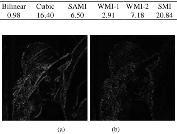
difference between the original high-resolution image and the interpolated images that are generated by the Cubic and WMI-2algorithm are shown in Figs. 3(a)-(b), respectively. Fig. 4 shows the simulation results PSNR (dB) for interpolated images of the Football sequence with increasing resolution by factor 2. In all simulation results, the images resulted from the interpolation with the new algorithm using wavelet transform achieve the better image quality and the speedy computation than those obtain with other approaches.
The more detail simulation results are can be found in the web page: http://www.cs.ccu.edu.tw/~hyl/WMI/.
Table 1. The PSNR values (in dB) of the images with
increasing resolution outside the training set.
Bilinear Cubic SAMI WMI-1 WMI-2 SMI Lena 35.77 36.97 36.23 37.39 37.89 38.02 Family 35.38 36.93 36.18 37.34 37.76 37.94 F-16 31.43 33.07 34.65 33.22 33.45 33.84 Baboon 24.50 25.34 25.24 25.71 25.88 25.85
Table 2. The execution time (in seconds) of the
interpolation schemes for image Lena.
Bilinear Cubic SAMI WMI-1 WMI-2 SMI 0.98 16.40 6.50 2.91 7.18 20.84
(a) (b)
Figure 3. Results of the difference between original
image and reconstructed image Lena: (a) interpolated by Cubic, and (b) interpolated by WMI-2.
25 27 29 31 33 35 1 4 7 10 13 16 19 22 25 28 Frame PSNR(dB) Bilinear Cubic SMNI WMI-2 WMI-1
Figure 4. The simulation results for interpolated images
of the Football sequence with increasing resolution by factor 2.
6.
CONCLUSIONS
In this paper, we proposed the efficient schemes for the digital image interpolation. The proposed algorithms increase the resolution of a low-resolution image by using the neural network. The SAMI scheme contains a simple window edge classifier which can avoid the disadvantages of using the edge-based interpolation schemes. The WMI scheme adopts the MLPs to predict all wavelet sub-images of high-resolution image in order to estimate the interpolated image more accurately. The wavelet analysis/synthesis procedure and MLP can be implemented easily by using VLSI techniques; thus the hardware design for the schemes is simple and efficient. Moreover, the proposed schemes can obtain the superior image quality and visual quality about edge region. From the experimental results, we find that the proposed schemes are expected to be useful interpolation schemes for natural images.
7.
REFERENCES
[1] K. Jensen and D. Anastassiou, "Subpixel edge localization and the interpolation of still images," IEEE Trans. Image
Processing, vol. 4, no. 3, Mar. 1995, pages 285-295.
[2] K. P. Hong, J. K. Paik, H. J. Kim, and C. H. Lee, "An edge-preserving image interpolation system for a digital camcoder," IEEE Trans. Consumer Electronics, vol. 42, no. 3, Aug. 1996, pages 279-284.
[3] A. M. Darwish, M. S. Bedair, and S. I. Shaheen, "Adaptive resampling algorithm for image zooming," IEE Proc.-Vis.
Image Signal Process, vol. 144, no. 4, Aug. 1997, pages.
207-212.
[4] M. Antonini, M. Barlaud, P. Mathieu, and I. Daubechies, "Image coding using wavelet transform," IEEE Trans.
Image Processing, vol. 1, no. 2, Apr. 1992, pages 205-220.
[5] T. Chang and C. J. Kao, "Texture analysis and classification with tree-structured wavelet transform,"
IEEE Trans. Image Processing, vol. 2, no. 4, Oct. 1993,
pages 429-441.
[6] Averbuch, D. Lazar, and M. Israeli, "Image compression using wavelet transform and multiresolution decomposition," IEEE Trans. Image Processing, vol. 5, no.
1, Jan. 1996, pages 4-15.
[7] S. Haykin, Neural Networks, Macmillan, New York, 1994. [8] T. Masters, Signal and Image Processing with Neural
Networks, Wiley, New York, 1994.
[9] R. H. Nielsen, "Theory of the back-propagation neural network," in Proc. Int. Joint Conf. Neural Networks, vol. 1, 1989, pp. 593-606.
[10]Y. Hirose, K. Yamashita, and S. Hijiva, "Back-propagation algorithm which varies the number of hidden units,"
Neural Networks, vol. 4, pages 61-66, 1991.
[11]J. D. Johnston, "A filter family designed for use in quadrature mirror filter banks," in Proc. IEEE Int. Conf.
Acoust., Speech, Signal Processing, 1980, pages 291-294.