Design and analysis of radial imaging capsule
endoscope (RICE) system
Mang Ou-Yang and Wei-De Jeng*
Department of Electrical Engineering, National Chiao-Tung University, Hsinchu City 300, Taiwan *[email protected]
Abstract: In this study, a radial imaging capsule endoscope (RICE) system is designed, which differs from a conventional front imaging capsule endoscope (FICE) system. To observe the wrinkled intima of the intestine, which spreads without folding around the circumference of the capsule when a capsule endoscope with a diameter that slightly exceeds that of the intestine passes through it, the RICE uses a cone mirror, a radial window shell, and a focus optical module that comprise the radial imaging system. This concept was demonstrated in a packaged optical simulator. The RICE optical model also has been established and verified by many simulations and experiments. In minimizing the sagittal and tangential aberrations, the optical module of the RICE has achieved an F-number of 4.2, a viewing angle of 65.08°, and an RMS radius of the 4th to 6th fields of less than 17 um. A comparison of these characteristics with those of the focus optical module that is used in FICE lenses reveals that the spot size is 50% larger for each field, and the modulation transfer function (MTF) is remarkably improved from 7% to 36% at 100 lp/mm on the 5th field of the sagittal plane.
©2011 Optical Society of America
OCIS codes: (170.2150) Endoscopic imaging; (170.3890) Medical optics instrumentation;
(120.3890) Medical optics instrumentation; (120.4570) Optical design of instruments.
References and links
1. Given imaging, M2A Given® Diagnostic System. http://www.givenimaging.com/
2. G. D. Meron, “The development of the swallowable video capsule (M2A),” Gastrointest. Endosc. 52(6), 817–819 (2000).
3. A. Uehara, and K. Hoshina, “Capsule endoscope NORIKA system,” Minim. Invasive Ther. Allied Technol.
12(5), 227–234 (2003).
4. T. Nakamura, and A. Terano, “Capsule endoscopy: past, present, and future,” J. Gastroenterol. 43(2), 93–99 (2008).
5. J. S. Chahl, and M. V. Srinivasan, “Reflective surfaces for panoramic imaging,” Appl. Opt. 36(31), 8275–8285 (1997).
6. D. W. Rees, “Panoramic television viewing system,” US Patent application 3505465 (April 1970). 7. J. Hong, X. Tan, B. Pinette, R. Weiss, and E. M. Riseman, “Image-based homing,” in Proceedings of IEEE
Conference on Robotics and Automation (IEEE, 1991), pp. 620–625.
8. Y. Yagi, and S. Kawato, “Panorama scene analysis with conic projection,” in Proceedings of IEEE/RSJ Workshop Intelligent Robots and Systems (IEEE, 1990), pp. 181–187.
9. H. Ishiguro, “Development of low-cost compact omnidirectional vision sensors and their applications,” in Proceedings of IEEE Conference on Information Systems, Analysis and Synthesis (IEEE, 1996), pp. 433–439. 10. M. Yachida, “Omnidirectional sensing and combined multiple sensing,” in Proceedings of IEEE and ATR
Workshop on Computer Vision for Virtual Reality Based Human Communications (IEEE, 1998), pp. 20–27. 11. S. Baker, and S. K. Nayar, “A theory of single-viewpoint catadioptric image formation,” Int. J. Comput. Vis.
35(2), 175–196 (1999).
12. M. Ou-Yang, S. W. Huang, Y. L. Chen, H. H. Lee, and P. K. Weng, “Design of wide-angle lenses for wireless capsule endoscopes,” Opt. Eng. 46(10), 103002 (2007).
13. M. Ou-Yang, S. W. Huang, W. K. Su, H. M. Feng, Z. Y. Chen, H. M. Wu, and Y. T. Kuo, “Optimizing the depth of field for short object distance of capsule endoscope,” Proc. SPIE 6859, 68591Q (2008).
14. V. N. Mahajan, Optical Imaging and Aberrations, Part I: Ray Geometrical Optics, (SPIE Press, 1998), Chap. 4. 15. V. N. Mahajan, Optical Imaging and Aberrations, Part II: Wave Diffraction Optics, (SPIE Press, 2001), Chap. 4. 16. D. Malacara, and Z. Malacara, Handbook of Optical Design, (Marcel Dekker, 2003), Chap. 4.
1. Introduction
As people work more and eat more colorful foods, their diet habits have become poorer, and the load on the typical digestive system has increased. Therefore, digestive diseases are becoming more varied and problematic around the world. Digestive diseases are typically observed using a colonoscope or a gastroscope. These invasive instruments usually make patients uncomfortable. The capsule endoscope, proposed and developed by Given Image Co. (GI) in 1999 [1,2], reduces the patient’s pain because the endoscope is shrunk and the data therefrom are transmitted wirelessly. The radio frequency (RF) system laboratory in Japan proposed a similar capsule endoscope system, NORICA3 [3], in 2003. Recently, Olympus capsule endoscopes were approved in Europe and have been commercialized [4]. The Olympus capsule endoscope represents breakthroughs in seven main technologies. Of particular note is the use of a magnetic field to control the direction of motion of the capsule in the intestine. This technology is very useful in the field of capsule endoscopes [4]. Until now, various types of the capsule endoscope have been used for special purposes, but most optical system designs have focused on capturing a clear front image, which cannot easily capture the wrinkle intima of the intestine. Pathological cells in the early stage are typically covered by the crepe intima and must be studied in advance of the problem. This fact motivates the present study.
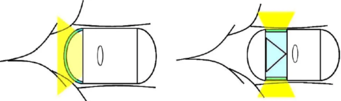
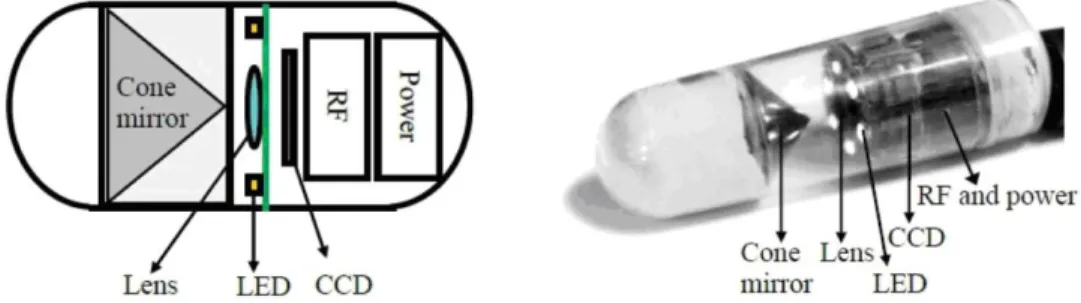
The conventional capsule endoscope captures a front view image. It is therefore called a front imaging capsule endoscope (FICE). The FICE has some inherent disadvantages, including difficulty of observation of the hidden regions of the wrinkle intima of the intestine, difficulty of determining the capsule speed and direction because all of the images are similar, difficulty of reconstructing a sequence of images at equal time intervals, and the need for a long depth-of–focus (DOF) optical module to obtain the front curved image of FICE, as shown in the left part of Fig. 1. Motivated by these difficulties, this study presents a new kind of capsule endoscope that utilizes a cone mirror, a radial window shell, and a focus optical module as an omni-directional vision system to solve the problems of the FICE system [5]. The new concept of the capsule endoscope, shown in the right part of Fig. 1, is to flatten the wrinkled intima at the circumference of the cylinder as the capsule endoscope with a slightly larger diameter than the intestine passes through it. All omni-directional images overlap each other, enabling the distance between each image to be calculated and the rate of motion of the capsule to be determined. Third, the lens does not require the use of long DOF lenses, which are required in the FICE to capture clear pictures. A long DOF lens is not simply a short object distance lens with a focus of tens of mm, which would comprise several aspherical lenses. The omni-directional system without a long DOF lens takes a radial image where the intestine is in contact with, or close to, the outer wall of the shell. Finally, the region of overlap in consecutive radial images allows an image of the intestines to be formed from a sequence of individual images obtained at equal time intervals. Accordingly, the medical professional can watch a video of the intestine using the distance and direction information reconstructed from the images. Such an omni-directional system for endoscopic applications was developed in this study and called the radial imaging capsule endoscope (RICE). Figure 1 shows the structures of the FICE and the RICE, and Fig. 2 shows the cross section of the RICE. The dotted circle represents the object plane of the intestine. The radial image is reflected and projected as a ring of images on the sensor plane.
Fig. 1. FICE (left) and RICE (right) system.
Fig. 2. Cross section of RICE system.
2. Design of Radial Imaging Capsule Endoscope
2.1 Reflective mirror in optical module
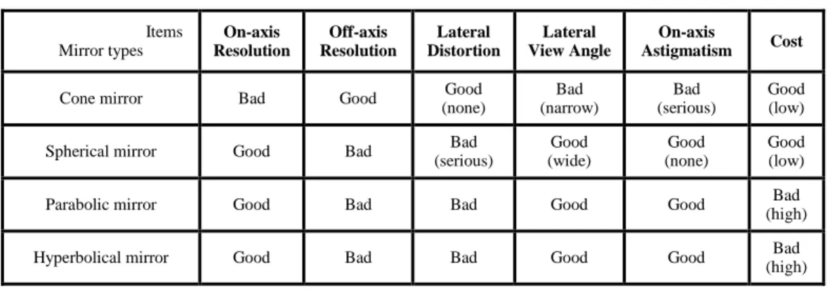
An optical module does not use lenses only to capture images. It uses various types of mirrors to shrink the module. Since the object plane is in the radial direction, which is perpendicular to the optical axis of the module, the axial symmetric reflector is introduced. It provides many advantages––it can change the direction of the propagation of rays, it minimizes the optical volume, and it captures images with the full viewing angle [6]. The capsule endoscope system uses a cylindrical reflector to obtain omni-directional images. However, cylindrical reflectors are associated with increased aberration and resolution problems. The four types of cylindrical reflectors are spherical mirrors, cone mirrors, parabolic mirrors, and hyperbolical mirrors [7– 10] listed in Table 1. Although the cone mirror has low resolution on-axis, it has high resolution off-axis, which is used to reconstruct the image because the image on the sensor plane is larger than the other omni-directional system. This setup is appropriate for use in the RICE system. Additionally the cone mirrors exhibit no tangential distortion or defocus problem because the lateral direction is effectively a flat mirror, which should generate a perfect image [11]. Serious on-axis astigmatism is prevented by cutting the problematic region out of the field of view during image processing. Furthermore, the cone mirror is easily manufactured accurately. In summary, cone mirrors have many advantages over other types of mirrors, and a cone mirror was used in the RICE system.
Table 1. Comparisons of Various Reflectors Items Mirror types On-axis Resolution Off-axis Resolution Lateral Distortion Lateral View Angle On-axis Astigmatism Cost
Cone mirror Bad Good Good (none) Bad (narrow) Bad (serious) Good (low) Spherical mirror Good Bad Bad
(serious) Good (wide) Good (none) Good (low) Parabolic mirror Good Bad Bad Good Good (high) Bad
Hyperbolical mirror Good Bad Bad Good Good Bad (high)
2.2. Design of optical lenses
The design of the optical module mainly concerns doublet lenses with a cone mirror. The doublet lenses were fabricated for use in the FICE, which treated the performance of the doublet lenses as an initial case to design the RICE system. When the lenses and the optical model are verified experimentally, the RICE system, based on the optical model, will be optimized [12].
Fig. 3. Rays propagation diagram.
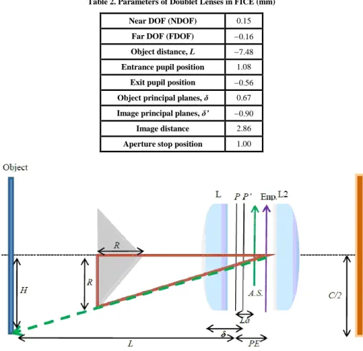
A cone mirror is important in the RICE system. The rays propagate from the object plane with an object length of H through the annular transparent viewing window of the shell and reflect on the cone mirror of radius R. The lenses then perform imaging on the image plane. The imaging principle of the RICE system clearly differs from that of the FICE system in Fig. 3. The parameter r denotes the inner radius; C is the diameter of the image circle and equals the length of the diagonal of the CCD; and x is the shell thickness (0.7 mm) plus the thickness of the liquid in the intestines (0.4 mm). This object distance ensures that the optical module can correctly capture images of the intestines and that the quality of the images is not affected by the liquid that is attached to the intestines; so, x is 1.1 mm [13]. Table 2 shows the specifications of the doublet lenses in the FICE. A geometric relation is used to determine the distances La and PE, as shown in Fig. 4. La is the distance between the object principal plane and the aperture stop––it equals 1.00-δ = 0.33 mm. PE is the distance between the object principal plane and the entrance pupil––it equals 1.08-δ = 0.41 mm. The transverse magnification is the ratio of the image distance and the object distance, which equals 0.383; H
denotes the width of the object and equals 5.29 mm. Finally, a similar triangle is used to determine that the cone mirror size R is 3.35 mm. Given these parameters, the optical module can be simulated in ZEMAX software.
Table 2. Parameters of Doublet Lenses in FICE (mm)
Near DOF (NDOF) 0.15
Far DOF (FDOF) 0.16
Object distance, L 7.48
Entrance pupil position 1.08
Exit pupil position 0.56
Object principal planes, δ 0.67
Image principal planes, δ’ 0.90
Image distance 2.86
Aperture stop position 1.00
Fig. 4. Distance between each element.
2.3 Aberration analysis
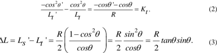
The geometry of the spherical surface mirror allows two directions to be defined. They are the tangential and sagittal planes. Astigmatism occurs because the sagittal and tangential planes cannot focus perfectly. However, spherical aberration can be compensated for by defocusing, and coma can be compensated for by tilting, so the corresponding aberrations are tolerable in the near diffraction limit [14,15]. This problem of astigmatism can be solved in many ways. Coddington’s equations are used herein to analyze the astigmatism phenomena associated with a cone mirror [16]. The parameter θ is the incident angle and
' is the refractive angle; Ls and Lt are the sagittal and tangential object distances; Ls’ and Lt’ are the sagittal and tangential image distances; R is the lens radius; and Ks and Kt are the sagittal and tangential powers, respectively. Here, n 1and
'are set for the mirror, and Eqs. (1) and (2) apply. When Ls and Lt become infinity, Ls’ and Lt’ equal the focal length, and the distance between Ls’ and Lt’ is ΔL, which is called the longitudinal astigmatism, yielding Eq. (3)., 1 1 ' ' cos cos Ks Ls Ls R (1)
2 2
,
' '
'
cos cos cos cos Kt Lt Lt R (2) 2 2
1
'
'
.
2
2
2
R
cos
R sin
R
L
L
s
L
t
tan sin
cos
cos
(3)Clearly, a spherical mirror cannot focus perfectly, and the factor R affects both tangential and sagittal image distances. However, for a cone mirror the tangential image distance is independent of R because the tangential plane acts as a plane mirror; so, the object distance equals the image distance, and the astigmatism problem arises only in the sagittal direction. Based on the results obtained by using the initial design the cone mirror radius R is 3.35 mm, and the distance between object H and the optical axis is D = r + x + NDOF = 6.253 mm. Here NDOF is near DOF of the doublet lenses; r is the inner radius; x is the shell thickness plus the liquid thickness in the intestines; and O is the principal position of the object. Therefore, the sagittal object distance is Ls = D-NR and θ =
' = 45°. The sagittal image distances for different radii can be determined. R can be substituted for NR where0 N 1. Hence, the radius of the sagittal direction of the spherical surface mirror is 2NR as shown in Fig. 5, P and P’ denote the object and image points, and P” is P’ projected onto the optical axis; therefore, Eqs. (1) and (2) are rewritten so the sagittal image distances are given by Eqs. (4) and (5):
, 1 1 2 ' ( ) 2N cos Ls r x NDOF NR R
(4)
.(
)
'
NR
r
x
NDOF
NR
Ls
r
x
NDOF
(5)Fig. 5. Imaging diagram on sagittal plane.
When the image distance has been determined for doublet lenses, the image points are collocated with the object points, and Fig. 6 shows the imaging situation when a cone mirror is used along with the associated astigmatism phenomena. The tangential and sagittal directions cannot focus perfectly and the image quality is seriously affected, so new doublet lenses are designed to improve this problem.
Fig. 6. Visual imaging by cone mirror.
2.4 Imager and associated electrical device
Since a cone mirror is used, an annular transparent viewing window can be installed on the side of the capsule to capture radial images. Lenses imaging the object on the sensor can be used and image data transferred to an electronic device. The specifications of the CCD sensor are 512 pixels × 512 pixels with a pixel size of 5.6 um and an inner capsule radius of 5 mm. The system uses an LED to illuminate the object, and the RF system transfers the data to a receiving device. All of the power is supplied by a battery, which can maintain the required power for approximately 8 hours. Figure 7 shows the system and its fabrication.
Fig. 7. RICE diagram (left) and RICE embodiment (right).
3. Modeling and Simulation
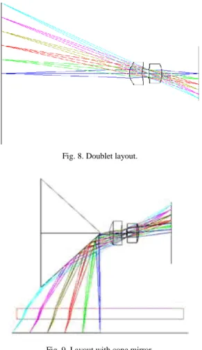
In general, in an optical design an initial case of doublet lenses of the FICE should first be simulated and then the parameters optimized. Figure 8 shows the initial design of the doublet lenses. Then a cone mirror is added to the design, and the surface type is set to “mirror” in ZEMAX, with the conic constant K equal to 2 because
is 45. These constants are substituted into Eq. (13):
2
.
90
1
k
tan
(13)However, the object is on the side of the radial imaging capsule endoscope, and a “coordinate break” command is required to rotate the direction by 90 with respect to the image plane. Also, the toroidal-shaped materials are used to add the annular transparent viewing window and the object plane. The window is made of polyurethane (PU), which does
not hurt the human body and has passed the test for safety by US Pharmacopoeia XXII Class VI; its index isnd 1.59, the Abbe coefficient is around 15.35, and the wavelength is within the range 365–1040 nm. Figure 9 shows the model.
Fig. 8. Doublet layout.
Fig. 9. Layout with cone mirror.
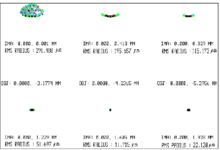
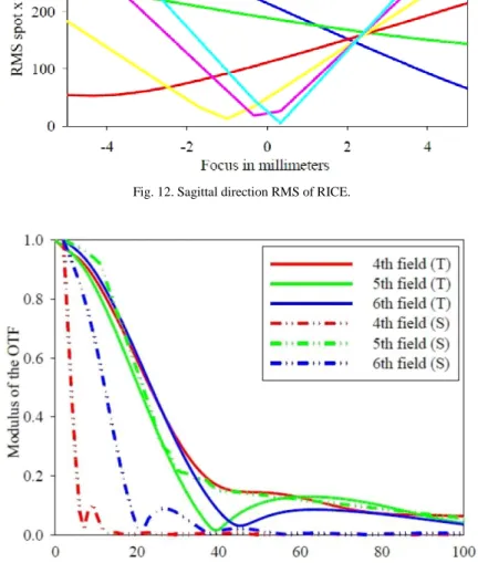
After the optical module is established, the parameters must be set for the simulation. Figures 10–13 show the results obtained by using the initial design. Clearly, the spot is too large in all fields, and the RMS radius of the 1st field exceeds 550 um, seriously affecting image quality, but the 4th–6th fields are much better. Figures 11 and 12 show imperfect focusing in the sagittal direction, as mentioned above; focusing is also imperfect in the 1st field because this field is a sharp point on the cone mirror. Figure 13 plots the modulation transfer function (MTF) data just from the 4th–6th fields of this system because the very serious decay of the other fields occurs at low frequency. The optical system performance appears to be very poor, but this is expected because the system that it is associated with requires FICE doublet lenses. Therefore, new doublet lenses are designed to be collocated with the cone mirror.
Fig. 10. Spot size of RICE.
Fig. 12. Sagittal direction RMS of RICE.
Fig. 13. MTF diagram of RICE.
4. Experiments and Analysis
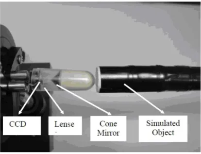
This section describes an experiment to check the correctness of the model. The devices used in the experiment are doublet lenses, a cone mirror, a three-axis platform, a sensor, an imaging electrical board, and a CPU. Figure 14 shows the setup.
Fig. 14. Experimental apparatus of RICE.
The first test is for astigmatism. The object is a grid pattern of height H = 5.29 mm divided into six fields and width = 2
5, or about 31.4 mm. The grid is rolled into an object tube to enable the radial direction to be easily scanned in the RICE system.The object is fixed and the image distance is varied to observe the degree of spreading of the grid lines. Figure 15 shows the experimental results. The ring image is in the sagittal direction, and another radial line is in the tangential direction. The image distances are 1.5 mm, 1.96 mm, 2.5 mm, and 3.0 mm. The simulation and experiment yield similar results because the ring and radial lines have almost the same focal positions.
Fig. 15. Simulation data are shown on the up row; the experiment data are shown on the bottom row.
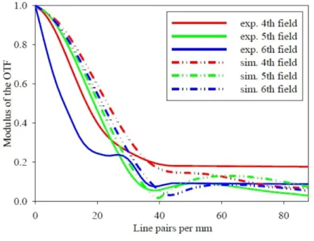
The second experimental task is the MTF measurement. The object is a white and black pattern. The image can be regarded as an edge spread function, which is differentiated to obtain the point spread function (PSF). Fourier transforming the function yields the MTF, so the tangential and sagittal directions of the MTF are shown in Figs. 16 and 17. Although the
simulated and experimental results are dissimilar, the MTF values in the 4th field always exceed those in the 5th field, and those in the 5th field exceed those in the 6th field in most regions. The cut-off frequency is 88 line pairs per millimeter, because the CCD pixel size is 5.6 um.
Fig. 16. Tangential MTF of RICE.
Fig. 17. Sagittal MTF of RICE.
The next experimental task is the measurement of the spot size. A parallel ray is normally incident onto the cone mirror, and the reflected rays are focused by the doublet lenses. The image plane is moved to get the minimum spot size. Table 3 presents the results; the
experimentally determined rms radius is not very similar to the simulated value, but the radii of the simulated and experimental spots similarly decline.
Table 3. Spot Sizes of Experiment and Simulation
Fields 1st 2nd 3rd 4th 5th 6th
Simulation 291 um 196 um 115 um 51 um 12 um 22 um
Experiment 323 um 132 um 91 um 46 um 39 um 32 um
In summary, the experimental data are all very similar to the simulated data. Hence, the presented optical model is correct, so the optical system can now be optimized.
5. Discussion and Results
The simulation and experiment indicate importantly that the concept of the RICE system is realized and workable in order to observe the wrinkle intima of the intestine. In order to improve the RICE image quality, we try to modify the FICE doublet lenses with the cone mirror for RICE system application. From the viewpoint of the radial image, the F-number and the position of the cone mirror of the optical system need to be optimized. The two factors could reduce the problem of astigmatism effectively and improve the image quality. Figure 18 shows the results that different F-numbers affect the spot size when the doublet lenses of the FICE served as the RICE application. The spot size would decrease when the F-number increased. However, a large F-number would induce less radiant power absorbed on the image sensor. Optimizing the spot size and radiant power, F-numbers equal to 4.2 were selected. The F-number change would be easy to achieve by replacing the smaller aperture stop without any modification of the curvature of the FICE doublet lenses. When the F-number was 4.2, the 2nd column in Table 4 showed the spot size was smaller than 20 um of 5th field when compared to 39 um of the experimental 5th field in Table 3. At the same time the MTF improved slightly from 7.5% to 14.6%.
Fig. 18. F-number vs. spot size of doublet lenses of FICE with cone mirror.
In order to find the best condition of doublet lenses for the RICE image, a new design for doublet lenses was proposed. Figures 19 and 20 showed the results of the newly designed doublet lenses with an F-number equal to 4.2, which was based on the previous analysis. The spot size had been improved greatly and was smaller than 17 um in the 4th, 5th, and 6th fields simultaneously, as shown in Fig. 19. The spot size was reduced more than 50% in every field. Furthermore, the MTF also progressed in every field. The largest MTF at 100 lps/mm happened at approximately 36% of the sagittal plane of the 5th field, as shown in Fig. 20.
Fig. 19. Spot size of new design doublet lenses with cone mirror.
Fig. 20. MTF size of new design doublet lenses with cone mirror.
Table 4 shows the results obtained using four doublet lenses––FICE doublet lenses with F-numbers of 2.8 and 4.2, as well as the newly designed doublet lenses with F-F-numbers of 5.6 and 4.2. Obviously, the newly designed doublet lenses with an F-number of 4.2 is superior to others, with the spot size smaller than 17 um in the 4th, 5th, and 6th fields. The largest MTF at 100 cycles per millimeter was increased from 7% to 36%. Although the image quality of the 1st, 2nd, and 3rd fields remained distorted, the aberrations could not be effectively reduced because the tip of the cone mirror is equivalent to a lens with a large curvature, which definitely induces unacceptable aberration and produces overlapping images in a small image area. Nevertheless, the 1st, 2nd, and 3rd fields could not be taken under image process consideration and were sacrificed. Based on the intrinsic characteristics of the radial image, image processing technology can be used to reconstruct the image with a uniform area of overlap across the 4th, 5th, and 6th fields. Furthermore, the area of overlap can be used to
estimate the distance moved. This feature is very useful for prediction of the capsule endoscope location.
Table 4. Four Types of Doublet Lenses for RICE System Lenses
Items Doublet Lenses of FICE New Designed Doublet Lenses
View angle 67.66° 65.08°
F-number 2.8 4.2 4.2 5.6
Radius of
cone mirror 4.024 4.069 4.769 3.748
Spot size<20μm NA 5th field 4th, 5th and 6th fields 5th and 6th fields
Largest MTF (100 lps/mm) 7.5% 3rd field (tangential) 14.6% 5th field (sagittal) 36% 5th field (sagittal) 13% 5th field (sagittal) 6. Conclusions
This study presents a cone mirror and focusing lenses to realize the RICE system, which can successfully capture radial images. Based on the optical theorem for designing radial imaging systems and analyzing the aberration that is caused by a cone mirror, the aberration phenomenon is solved in the proposed system using Coddington’s equations, which indicate that a cone mirror will cause astigmatism intrisically, making the sagittal and tangential image distances mutually inconsistent. To search the key parameters of doublet lenses with a cone mirror employing the RICE system, four different doublet lenses are proposed and analyzed. We obtain a newly designed doublet lenses with an F-number of 4.2, which is suitable for the RICE system. Its features optimized both spot sizes and MTFs on 4th, 5th, and 6th fields and ignored the 1st to 3rd fields. In the future, the RICE system can design a new cone mirror with an aspherical curvature, which possibly would improve the astigmatism and MTF further, because the mirror with an aspherical curvature could compensate for different fields of astigmatism by changing the sag surface.
Acknowledgments
This work is supported by the Chung-Shan Institute of Science & Technology of Taiwan under project CSIST-442-V202 and the National Science Council of Taiwan under contracts NSC 99-2622-E-009-023-CC1 and NSC 99-2218-E-039-001. The authors also thank Zhao-Yu Chen of Delta Electrics, INC, Hsien-Ming Wu, and Ping-Kuo Weng of the Chung-Shan Institute of Science & Technology, who provided experimental assistance and useful information.