As-quenched microstructure of a Cu–14.6Al–4.3Ni alloy
J. Tan, T.F. Liu
∗Department of Materials Science and Engineering, National Chiao Tung University, Hsinchu 300, Taiwan, ROC Received 20 October 1999; received in revised form 6 July 2000; accepted 10 July 2000
Abstract
In the as-quenched condition, the microstructure of the Cu–14.6Al–4.3Ni alloy is D03phase containing extremely fine precipitates.
Transmission electron microscopy examinations indicated that the extremely fine precipitates are L–J phase, rather than 2H phase. In addition, electron diffraction analyses indicated that the L–J precipitate has two variants with the D03 matrix. These results are quite
different from those reported by other workers in a Cu–14.2Al–4.3Ni alloy. © 2001 Elsevier Science B.V. All rights reserved. Keywords: Cu–14.6Al–4.3Ni alloy; 2H phase; L–J phase; Variants
1. Introduction
When Cu–Al binary alloys within the composition range from 11.0 to 14.7 wt.% Al were heated at a point in the sin-gle disordered bcc phase region and then quenched into room temperature water or ice-cooled brine, a → 1(D03
type) → ␥0 (orthorhombic) phase transition would occur during quenching by an ordering transition and a martensitic transformation, respectively [1–6]. In order to suppress the martensitic transformation, nickel was added to the Cu–Al binary alloys [7–10]. In 1966, P.R. Swann reported that the addition of 2.0 wt.% nickel in a Cu–14.6Al alloy does not introduce any new phases, but could prevent the martensitic transformation of the high temperature phase on quenching to room temperature [7]. This means that the as-quenched microstructure of the Cu–14.6Al–2.0Ni alloy was single D03
phase. However, when the nickel content was increased to 4.3 wt.%, a high density of extremely fine precipitates could be detected within the D03 matrix in the as-quenched
al-loy [9,10]. By using electron diffraction method, the crystal structure of the extremely fine precipitates was determined to be of the 2H type [9].
Recently, we have made transmission electron mi-croscopy examinations on the as-quenched microstructure of the Cu–14.6Al–4.3Ni alloy. Based on our present study, it is found that the extremely fine precipitates formed within the D03matrix should belong to the L–J phase, rather than
2H phase. The L–J phase was found and identified by the present workers in an as-quenched Cu2.2Mn0.8Al alloy [11].
∗Corresponding author.
E-mail address: [email protected] (T.F. Liu).
2. Experimental procedure
The alloy examined in the present study was prepared in a vacuum induction furnace under a controlled protec-tive argon atmosphere by using 99.9% copper, 99.9% alu-minum and 99.9% nickel. The melt was chill cast into a 30 mm×50 mm×200 mm copper mold. After being homog-enized at 1000◦C for 72 h, the ingot was sectioned into 2 mm thick slices. These slices were subsequently heat-treated at 1000◦C (in the single -phase state) for 1 h and then quenched into iced brine rapidly.
Electron microscopy specimens were prepared by means of a double-jet electropolisher with an electrolyte of 70% methanol and 30% nitric acid. Electron microscopy was performed on a JEOL 2000FX scanning transmission elec-tron microscope operating at 200 kV. This microscope was equipped with a Link ISIS 300 energy-dispersive X-ray spec-trometer (EDS) for chemical analysis. Quantitative analyses of elemental concentrations for Cu, Al and Ni were made with the aid of a Cliff–Lorimer Ratio Thin Section method.
3. Results and discussion
Fig. 1 represents a typical EDS spectrum of the present al-loy in the as-quenched condition. The quantitative analyses of 10 different EDS spectra indicated that the average chem-ical composition was Cu: 14.6±0.3 wt.%, Al: 4.3±0.2 wt.% Ni (Cu: 28.7 ± 0.6 at.%, Al: 3.7 ± 0.2 at.% Ni).
Fig. 2(a) is a bright-field (BF) electron micrograph of the as-quenched alloy, exhibiting the presence of the extremely fine precipitates with a mottled structure within the matrix. This feature is similar to that observed by other workers
0254-0584/01/$ – see front matter © 2001 Elsevier Science B.V. All rights reserved. PII: S 0 2 5 4 - 0 5 8 4 ( 0 0 ) 0 0 4 0 2 - 8
50 J. Tan, T.F. Liu / Materials Chemistry and Physics 70 (2001) 49–53
Fig. 1. A typical EDS profile of the present alloy in the as-quenched condition.
Fig. 2. Electron micrographs of the as-quenched alloy. (a) BF, and (b)–(i) eight SADPs. The zone axes of the D03 and L–J phases are: (b) [1 0 0]D03,
[0 2 1]1, [0 2 1]2; (c) [3 1 1]D03, [0 1 2]1, [1 2 1]2; (d) [1 2 1]D03, [¯3 ¯8 5]1, [3 0 1]2; (e) [1 1 0]D03, [¯1 0 1]1, [1 0 1]2; (f) [3 ¯3 1]D03, [3 5 1]1, [¯3 1 4 1]2; (g)
[1 1 1]D03, [0 ¯1 1]1, [3 2 1]2; (h) [3 2 1]D03, [¯1 0 3]1, [9 8 7]2; and (i) [3 3 1]D03, [¯3 ¯2 5]1, [3 1 2]2, respectively. (hkl= D03 phase, hkl1or2= L–J phase, 1:
variant 1; 2: variant 2).
[9]. Fig. 2(b)–(i) demonstrate eight different selected-area diffraction patterns (SADPs) of the as-quenched alloy. These figures show that in addition to the reflection spots corre-sponding to the D03 phase [10,12–15], the diffraction
pat-terns also consist of extra spots caused by the presence of the extremely fine precipitates. Compared to the previous study [9], it is found that the positions and streak behaviors of the extra spots in Fig. 2(b)–(e) are the same as those observed by other workers in the Cu–14.2Al–4.3Ni alloy [9]. In their studies, these four different SADPs were used to determine the crystal structure of the extremely fine precipitates. It was pointed out that the extra spots in Fig. 2(d) and (e) could be explained by both the structure and the 2H type structure; while the extra spots in Fig. 2(b) and (c) could not be ac-counted for by the structure, but by the 2H type structure. Consequently, they concluded that the 2H type structure was more appropriate than the structure for accounting
Fig. 2 (Continued).
for these extra reflections. The 2H phase has an orthorhom-bic structure with lattice parameters a = 0.4274 nm, b = 0.5393 nm and c = 0.4127 nm [9]. Therefore, it may be deduced that the extremely fine precipitates formed in the present alloy were of the 2H type phase. However, a further analysis indicated that the extra spots in Fig. 2(f)–(i) could not be indexed completely in terms of the lattice parameters of the 2H phase. Furthermore, a detailed dark-field (DF) electron microscopy examination indicated that all of the extra spots in Fig. 2 should come from the same type of precipitates. A typical example is shown in Fig. 3. Fig. 3(a) and (b) are two DF electron micrographs, which were taken
Fig. 3. (a)–(b) Two DF electron micrographs, which were taken with the reflection spots marked as 1 and 2 in Fig. 2 (b) and (f), respectively.
with the reflection spots marked as 1 and 2 in Fig. 2(b) and (f), respectively. It is obvious that the precipitates presented in Fig. 3(a) and (b) are completely identical. However, the reflection spot marked as 1 in Fig. 2(b) can be indexed as 2H phase, but not the reflection spot marked as 2 in Fig. 2(f). Therefore, it is reasonable to suggest that the extremely fine precipitates should not be of the 2H type phase.
However, when compared with the previous study of the present workers in the Cu2.2Mn0.8Al alloy [11], it is clear
that the positions and streak behaviors of the extra spots in Fig. 2(b)–(i) are the same as those of the L–J phase. The L–J phase has an orthorhombic structure with lattice parameters
52 J. Tan, T.F. Liu / Materials Chemistry and Physics 70 (2001) 49–53
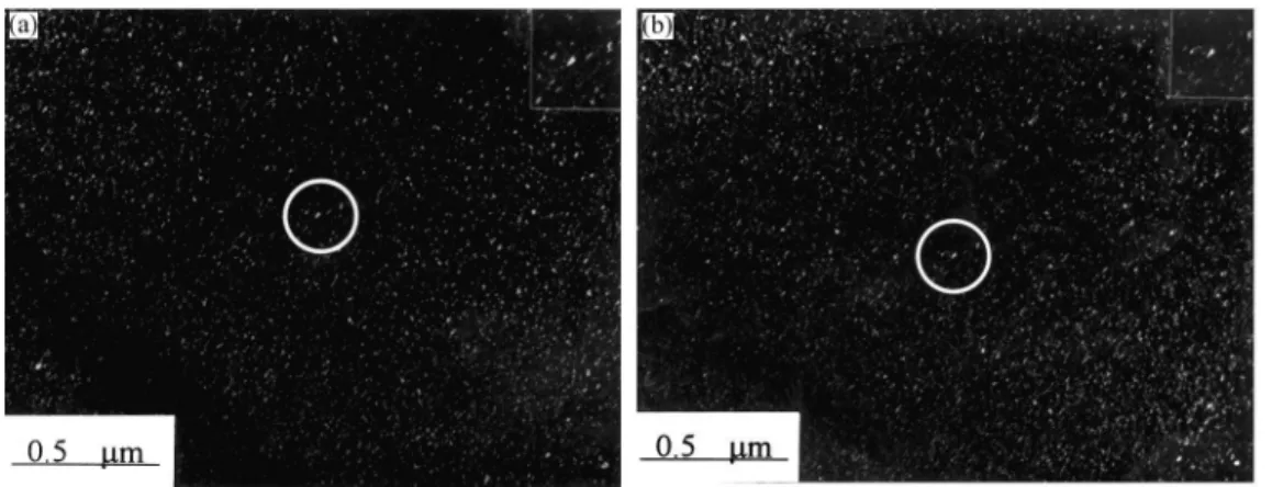
Fig. 4.g = [1 1 1] D03 DF electron micrograph of the same area as in
Fig. 2(a).
a = 0.413 nm, b = 0.254 nm and c = 0.728 nm. The
ori-entation relationship between the L–J phase and the matrix can be stated as (1 0 0)L–J//(0 ¯1 1)mand (0 1 0)L–J//(1 ¯1 ¯1)m.
Therefore, it is confirmed that the extremely fine precipi-tates should belong to the L–J phase, rather than 2H phase. Fig. 4 shows ag = [1 1 1] D03 DF electron micrograph of
the as-quenched alloy, clearly revealing the presence of the D03domains. In this figure, it is also seen that a high
den-sity of the extremely fine L–J precipitates (dark contrast) is
Fig. 5. (a) An exact [1 0 0] electron diffraction pattern of the as-quenched alloy. (b)–(c) two SADPs, which were tilted slightly away from the exact [1 0 0] zone axis about [0 2 ¯2] and [0 2 2] directions, respectively. The zone axes of the D03 and L–J phases are: (b) [1 0 0]D03, [0 2 1]1; (c) [1 0 0]D03,
[0 2 1]2. (hkl= D03 phase, hkl1or2= L–J phase, 1: variant 1; 2: variant 2).
present within the D03domains. Based on the above
obser-vations, it is concluded that the as-quenched microstructure of the present alloy is D03phase containing extremely fine
L–J precipitates.
Finally, one experimental result is worth mentioning. In the previous study [9], Otsuka et al. pointed out that only one variant of the extremely fine precipitates was observed, which was determined principally by using an [1 0 0] electron diffraction pattern. However, two variant reflection spots could be investigated in the present study. In order to clarify this difference, the electron diffraction method was undertaken. Fig. 5(a) shows an exact [1 0 0] electron diffraction pattern of the as-quenched alloy, indi-cating that only D03 superlattice reflection spots and faint
streaks along h0 2 2i directions can be observed. By tilt-ing the thin foil slightly away from the [1 0 0] zone axis about [0 2 ¯2], it was found that not only the streaks be-came pronounced but one variant L–J reflection spot started to appear, as indicated in Fig. 5(b). Similarly, when the thin foil was tilted about [0 2 2], the former variant dis-appeared and the other variant dis-appeared, as illustrated in Fig. 5(c). However, two variant reflection spots became visible simultaneously when the thin foil was tilted about [0 4 0], as shown in Fig. 2(b). This may be the one possi-ble reason to account for the difference between the two works.
4. Conclusions
The as-quenched microstructure of the Cu–14.6Al–4.3Ni alloy is D03 phase containing extremely fine precipitates.
The extremely fine precipitates should belong to the L–J phase, rather than 2H phase. The L–J precipitates have two variants with the D03matrix.
Acknowledgements
The authors are pleased to acknowledge the financial sup-port of this research by the National Science Council, Re-public of China under Grant NSC88-2216-E009-017. They are also grateful to M.H. Lin for typing.
References
[1] G. Wasserman, Metalwirtschaft 8 (1934) 133.
[2] V. Gridnev, G. Kurdjumov, Tech. Phys. U.S.S.R. 5 (1938) 263. [3] A.B. Greninger, Trans. A.I.M.E. 133 (1939) 204.
[4] G.V. Kurdjumov, V. Miretzky, T. Stelletzkaja, J. Phys. 3 (1940) 297. [5] Z. Nishiyama, S. Kajiwara, Jap. J. Appl. Phys. 2 (1963) 478. [6] N. Nakanishi, Trans. JIM 2 (1960) 79.
[7] P.R. Swann, Phil. Mag. 14 (1966) 461.
[8] M.J. Duggin, W.A. Rachinger, Acta Metall. 12 (1964) 529. [9] K. Otsuka, H. Sakamoto, K. Shimizu, Trans. JIM 20 (1979) 244. [10] J. Singh, H. Chen, C.M. Wayman, Metall. Trans. A 17A (1986)
65.
[11] S.C. Jeng, T.F. Liu, Metall. Trans. A 26A (1995) 1353.
[12] T.F. Liu, J.S. Chou, C.C. Wu, Metall. Trans. A 21A (1990) 1891. [13] T.F. Liu, C.M. Wan, Scripta Metall. 19 (1985) 805.
[14] C.C. Wu, J.S. Chou, T.F. Liu, Metall. Trans. A 22A (1991) 2265. [15] N. Kuwano, C.M. Wayman, Metall. Trans. A 15A (1984) 621.

![Fig. 4. g = [1 1 1] D0 3 DF electron micrograph of the same area as in](https://thumb-ap.123doks.com/thumbv2/9libinfo/7506795.117129/4.918.145.430.107.325/fig-g-d-df-electron-micrograph-area.webp)
