A Low-Complexity Synchronizer
for OFDM-Based UWB System
Hsuan-Yu Liu, Student Member, IEEE, and Chen-Yi Lee, Member, IEEE
Abstract—In current ultra-wideband (UWB) baseband
synchro-nizer approaches, the parallel architecture is used to achieve over 500 MSamples/s throughput requirement. Therefore achieving low power and less area becomes the challenge of UWB base-band design. In this paper, a low-complexity synchronizer combining data-partition-based correlation algorithms and dy-namic-threshold design is proposed for orthogonal frequency division multiplexing based UWB system. It provides a method-ology to reduce design complexity with an acceptable performance loss. Based on the data-partition algorithms, both single auto-cor-relator and moving-average-free matched filter are developed with 528 Msample/s throughput for the 480 Mb/s UWB design. Simulation results show the synchronization loss can be limited to 0.8-dB signal-to–noise ratio for 8% system packet-error rate.
Index Terms—Data-partition, dynamic-threshold,
moving-av-erage-free matched filter (MF), single auto-correlator.
I. INTRODUCTION
O
RTHOGONAL frequency division multiplexing (OFDM) based ultra-wideband (UWB) technology has received attention owing to the provided 480 Mb/s high data rate and below 323 mW power requirement [1]. In baseband receiver, the timing and frequency synchronizer is used to detect the incoming packet and solve the carrier frequency offset (CFO) which is expected as 20 ppm for UWB [2]–[6], [10]. In the WLAN system, existing synchronizers use the matched filter (MF) and the fast-Fourier-transform (FFT) symbols for accurate timing detection and fine CFO estimation [3]–[7]. However, the moving-average circuit of MF and registers storing FFT symbol will consume large power, i.e. 110 mW in [3]. As the system migrates to UWB, parallel architecture is exploited. References [8] and [9] use 20 and 128 parallel MF to detect the symbol timing in 10- and 2-GHz sampling rates respectively. Thus, achieving low power becomes the main concern in designing UWB baseband synchronizer [8].To achieve a power-efficient synchronizer for OFDM-based UWB system, a novel low-complexity scheme combining a data-partition and dynamic-threshold design is proposed. The data-partition method can reduce the used data amount
Manuscript received December 22, 2004; revised June 14, 2005. This work was supported by the National Science Council of Taiwan, R.O.C. under Grant NSC94-2215-E-009-044, and by the Ministry of Economic Affairs of Taiwan, R.O.C. under Grant 93-EC-17-A-03-S1-0005. This paper was recommended by Associate Editor T. S. Rosing.
The authors are with the Department of Electronics Engineering, National Chiao Tung University, Hsin-Chu 300, Taiwan, R.O.C. (e-mail: hyliu@si2lab. org; [email protected]).
Digital Object Identifier 10.1109/TCSII.2006.882804
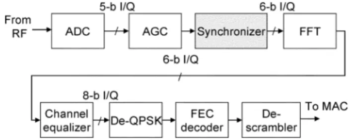
Fig. 1. System block diagram of OFDM-based baseband receiver.
for synchronization (Sync), thus the register-access amount and moving-average complexity can be reduced. The dy-namic-threshold design can adapt the threshold value of timing detection to the channel condition, thus enhancing the Sync performance. Simulation result shows the performance loss of the proposed design with 75% register reduction can be limited to 0.8-dB signal-to–noise ratio (SNR) for 8% system packet-error rate (PER). This paper is organized as follows. System block diagram of UWB baseband receiver is described in Section II. The proposed low-complexity scheme is described in Section III. Simulated results are shown in Section IV. The proposed architecture and implementation result are described in Section V.
II. SYSTEMBLOCKDIAGRAM
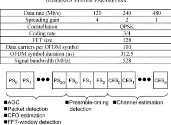
Fig. 1 shows the system block diagram of the UWB baseband receiver. And system parameters are listed in Table I [12]. In the receiver, after the automatic gain control (AGC) adjusts the RF gain the proposed synchronizer begins to detect the incoming packet. physical layer convergence protocol (PLCP) preamble transmitted in the initial of each packet can be used for Sync. The structure of PLCP preamble defined in [10] is shown in Fig. 2. The preamble comprises 21 packet sequences (PS), three frame sequences (FS), and six channel-estimation sequences (CES). In the preamble the proposed design can sequentially finish packet detection (PD), CFO estimation, FFT-window de-tection (FWD), and preamble-timing dede-tection (PTD). After the synchronizer, the received signal is sent through FFT, channel equalizer, the de-quadrature phase shift key (QPSK), the for-ward error control (FEC) decoder, and de-scrambler, and then the data are sent to medium access control (MAC).
III. ALGORITHMDESIGN
A. Data-Partition-Based Auto-Correlation
In order to detect the repeated PS of the incoming preamble and estimate the CFO from the linear phase rotation caused by CFO, the auto-correlation (AC) can be used in the
TABLE I
BASEBANDSYSTEMPARAMETERS
Fig. 2. Preamble structure of OFDM-based UWB system.
based OFDM system [2]–[6]. The algorithm used in the existing approaches can be derived as
(1) where is the sample amount of a repeated symbol, and is the received sample in the th cycle of the th repeated symbol. In the UWB system, the preamble comprises the repeated OFDM symbols and each of which has 165 sam-ples [10]. So is equal to 165 in the OFDM system with 128-point FFT symbol and 37-sample guard-interval. And the 165 samples will be stored and multiplied in (1). To reduce the multiplications, a data-partition-based AC algorithm is proposed and derived as
(2) where is the reduction factor and
are the used samples. In the proposed algorithm, input data are partitioned into groups, and only one group of data is used. Thus the multiplications can be reduced to . And the regis-ters for storing the input samples can be also reduced. The AC output power can be used to detect valid packet. The algorithm of PD can be derived as
(3) where is the AC output power, is a pre-defined threshold value, and is the sum of signal power of
th OFDM symbol. Fig. 3 shows the examples of normalized AC power of the received signal in a high SNR condition of an AWGN channel (better channel) and a low SNR condition of an indoor multipath channel for UWB system (worse channel) [11]. The correct preamble is set to begin in 0 ns. Before 0 ns only the noise comes. And the normalized AC power of received noise may become higher as is increased. That means the larger value will cause the false-alarm of PD more easily. So it’s important to find a value to simultaneously
Fig. 3. Normalized AC power in (a) better channel and (b) worse channel.
keep Sync performance and reduce design complexity. The AC can be also used for CFO estimation [3]–[7]. The CFO estima-tion can be derived as
(4) where is the estimated CFO, is the sample amount of an OFDM symbol, is the sample period, and is the AC result. After CFO estimation, the phase rotation caused by CFO can be compensated, and FWD can begin without CFO distor-tion.
B. Moving-Average-Free MF
For correct FWD, the MF can be used [4], [5]. The algorithm used in existing approaches can be derived as
(5) where is the sample amount of an OFDM symbol, is the FWD timing from 0 to , is the received sample after CFO compensation, and is the coefficient of the MF. The conventional MF in (5) needs to store the received samples in the registers according to different FWD timing . We propose a moving-average-free MF which only stores no matter what the value of timing k. And the register power can be reduced. Since the OFDM symbol is repeated, the received samples have a period of N samples. And the received sample , where , can approximate to . And then the received samples , where
, can approximate to , where
and . That means the used received samples can be only for different FWD timing . Equation (5) can be approximated as
Fig. 4. MF power in (a) better channel and (b) worse channel.
where the used received samples are fixed as , and
the MF coefficients are still .
Since the proposed algorithm can only use fixed N received sam-ples to calculate all outputs of the MF, the moving-average de-sign is not needed. Moreover the computation of the moving-av-erage-free MF can be still reduced by the data-partition method. Finally, the proposed MF algorithm can be derived as
(7)
where the index is the reduction factor as in (2). As (2), mul-tiplications and stored samples of (7) can be reduced to of the original amounts. The filter taps can be also reduced. The MF output power can be used for FWD. The timing when MF peak power appears can be derived as
(8) where is the timing with peak power and is the MF output power. Fig. 4 shows the MF power of the re-ceived preamble in the channel conditions which is the same as in Fig. 3. As shown in Fig. 4, the correct FFT-window (FW) boundary is set to 0 ns. As is increased, the highest peak of MF output power will not only appear in the FW boundary (0 ns). For solving the problem the sub-optimal timing location al-gorithm can be used [5]. And the FW boundary can be detected as the timing of the earliest searched MF peaks. As shown in Fig. 4 when is equal to 4, the correct FW boundary (0 ns) is the timing of the earliest one of 2 highest peaks. In this case we can search 2 MF peaks and detect the FW boundary on the ear-liest peak. The sub-optimal timing location algorithm can help to adjust the FWD result according to the chosen value.
C. Dynamic-Threshold Design
After FWD, the synchronizer can start the PTD to find the boundary between PS and FS of the preamble. Since the FS is the sign-inversed signal of PS [10], we can use sum of two
continuous AC results to detect the timing. The algorithm of PTD can be derived as
(9) where is the AC result of th and th OFDM symbol, is a threshold value, and is the sum of signal power of the mth OFDM symbol. If the th OFDM symbol be-longs to PS and th OFDM symbol belongs to FS, the sign-inversed characteristic will let be sign-inversed
of . Thus will
be-come smaller than the product of threshold and sum of the signal power. For accurate PTD, a dynamic-threshold design, which adapts value to the channel condition, is proposed. The adapted threshold can be derived as
(10) where is a fixed ratio to shift the level of to perform accurate PTD, and the threshold value can be updated according to AC result and sum of signal power and . Simulation result shows the proposed dynamic threshold design can achieve the lower FER and PER than those fixed threshold designs.
IV. SIMULATIONANALYSIS
System PER and FER of the proposed design is shown in this section. The simulation environment mainly comprises additive white Guassian noise (AWGN), CFO effect, SCO effect, and the indoor multipath channel [11] with typical 5 ns RMS delay spread for 480 Mb/s UWB system. The CFO and SCO between transmitter and receiver design are both set as 40 ppm
.
A. PER Analysis of Data-Partition-Based Design
As shown in Fig. 5, system PER of the proposed low-com-plexity scheme with different reduction factor is simu-lated and compared with perfect Sync ( and ) in 480 Mb/s data rate mode. Compared with the perfect Sync, the SNR loss for typical 8% PER is 0.14, 0.15, 0.3, and 3.1 dB of , 2, 4, and 8. The design with is not efficient to achieve 8% PER. The PER curves of , 2, 4 are very close to each other, and the SNR loss becomes obviously higher when is 8.
B. FER and PER Analysis of Dynamic-Threshold Design
Fig. 6 shows the FER of the proposed dynamic-threshold de-sign compared with fixed-threshold dede-signs. The dede-signs with and 0.1 can respectively achieve the low FER in 0-dB and 2 6-dB SNR regions. However they can’t achieve the lowest FER in all SNR regions. The proposed dy-namic-threshold design can achieve the lowest SNR regions be-cause of the adapted threshold tuning. Fig. 7 shows the PER of the proposed dynamic-threshold design in 120 Mb/s data rate. Since the proposed design can achieve the lowest FER, it can
Fig. 5. Floating-point PER with different! values in 480 Mb/s mode.
Fig. 6. FER with different threshold of PTD.
Fig. 7. PER with different threshold of PTD in 120 Mb/s data rate.
achieve lower 0.13-dB 2.33-dB SNR for 8% PER compared with the fixed-threshold designs.
Fig. 8. Fixed-point PER of the proposed design.
C. Fixed-Point PER Performance
Fig. 8 shows the PER of the fixed-point baseband processor with the proposed design with in 120 Mb/s 480 Mb/s data rates. And the 5-bit digital-to-analog converters (DACs) and analog-to-digital converters are adopted. Compared with perfect Sync, the SNR loss caused by Sync error is only 0.15 0.8 dB for typical 8% PER in 120 Mb/s 480 Mb/s data rates. The proposed design with can efficiently suppress the Sync error and enhance system performance.
V. ARCHITECTUREDESIGN
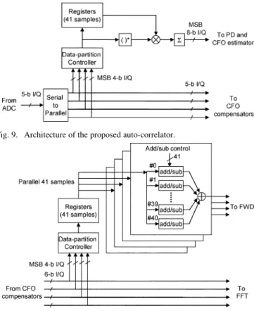
In order to efficiently achieve 528 Msamples/s throughput for UWB specifications, the synchronizer is designed with four par-allel signal paths at 132-MHz clock frequency. The architecture of the proposed auto-correlator with is shown in Fig. 9. Since the computation of AC can be reduced to quarter in (2), only one auto-correlator is needed instead of the parallel four auto-correlators. And the stored sample amount for the auto-cor-relator can be also reduced to . Architec-ture of the proposed MF is shown in Fig. 10. Based on (7), the needed tap number of MF is reduced from N to . In [10], the preamble has the constant magnitude and varied sign values. So the MF can be realized with addition/subtraction de-sign instead of the de-signed multipliers. And like the auto-corre-lator, the proposed moving-average-free MF also needs to store 41 samples. So the registers for storing 41 samples can be shared by the auto-correlator and MF. Based on the proposed low-com-plexity scheme, the synchronizer can be realized with a single auto-correlator, the quarter-tap moving-average-free MF, and the quarter-size registers.
Table II lists the hardware comparison of the proposed de-sign and a parallel approach with 4 parallel auto-correlators, 4 parallel 165-tap MF, and 165-sample registers. The power com-parison is based on the post-layout simulation in 528 MSam-ples/s throughput and the standard 0.18- m CMOS process. Be-sides the auto-correlator, MF, and registers, the synchronizer designs also contain CFO compensators which are realized by complex multipliers to compensate the phasor error. With the reduced auto-correlator, MF, and registers, the proposed design
Fig. 9. Architecture of the proposed auto-correlator.
Fig. 10. Architecture of the proposed MF.
TABLE II HARDWARECOMPARISON
needs only 37.6% gate count and 43.3% power of the parallel approach.
Table III lists the chip testing summary and Fig. 11 shows the chip microphoto. Designed in 0.18- m CMOS process, the pro-posed synchronizer consumes 33 mW for 480 Mb/s data rate and 528 Msamples/s throughput. It occupies 20.4% of the OFDM receiver (RX) power. The proposed low-power scheme reduces 26.7% of OFDM receiver power when compared with the par-allel approach.
VI. CONCLUSION
After algorithm introduction, performance analysis, and ar-chitecture design, a low-complexity synchronizer is proposed for OFDM-based UWB baseband processor. Combining data-partitioning and dynamic-threshold schemes, the proposed de-sign can achieve 528 Msamples/s throughput to meet 120 480 Mb/s data rates in 0.18- m CMOS process. It needs 37.6% gate count and consumes only 43.3% power of the parallel approach.
TABLE III CHIPTESTINGSUMMARY
Fig. 11. Chip microphoto of the OFDM-based UWB baseband transceiver.
REFERENCES
[1] A. Batra, J. Balakrishnan, G. R. Aiello, J. R. Foerster, and A. Dabak, “Design of a multiband OFDM system for realistic UWB channel environments,” IEEE Trans. Microw. Theory Tech., vol. , no. 9, pp. 2123–2138, Sep. 2004.
[2] T. M. Schmidl and D. C. Cox, “Robust frequency and timing syn-chronization for OFDM,” IEEE Trans. Commun., vol. 45, no. 12, pp. 1613–1621, Dec. 1997.
[3] M. Krstic, A. Troya, K. Maharatna, and E. Grass, “Optimized low-power synchronizer design for the IEEE 802.11a standard,” in Proc. ICASSP, Apr. 2003, vol. 2, pp. II-333–II-336.
[4] L. Schwoerer, “VLSI suitable synchronization algorithms and architec-ture for IEEE 802.11a physical layer,” in Proc. IEEE Int. Symp. Circuits Syst., May 2002, vol. 5, pp. 721–724.
[5] C.-F. Hsu, Y.-H. Huang, and T.-D. Chiueh, “Design of an OFDM re-ceiver for high-speed wireless LAN,” in Proc. IEEE Int. Symp. Circuits Syst., May 2001, vol. 4, pp. 558–561.
[6] J. Liu and J. Li, “Parameter estimation and error reduction for OFDM-based WLANs,” IEEE Trans. Mobile Comput., vol. 3, no. 2, pp. 152–163, Apr. 2004.
[7] C. S. Peng and K. A. Wen, “Synchronization for carrier frequency offset in wireless LAN 802.11a system,” Wireless Personal Multimedia Communications, vol. 3, pp. 1083–1087, Oct. 2002.
[8] M. Verhelst, W. Vereecken, M. Steyaert, and W. Dehaene, “Architec-ture for low ultra-wideband radio receivers in the 3.1–5-GHz band for data rates<10 Mbps,” in Proc. Int. Symp. Low Power Electron. Des., Aug. 2004, pp. 280–285.
[9] I. D. O’Donnell, S. W. Chen, B. T. Wang, and R. W. Brodersen, “An integrated, low power, ultra-wideband transceiver architecture for low-rate indoor wireless system,” in Proc. IEEE CAS Workshop Wireless Commun. Network., Sep. 2002.
[10] A. Batra et al., Multi-Band OFDM physical layer proposal Sep. 2003, IEEE P802.15-03/267r6-TG3a.
[11] J. Foerster, Channel modeling sub-committee report, final Feb. 2003, IEEE P802.15-02/490r1-SG3a.
[12] H.-Y. Liu et al., “A 480 Mb/s LDPC-COFDM-based UWB baseband transceiver,” in Dig. Tech. Papers IEEE Int. Solid-State Circuits Conf., Feb. 2005, pp. 444–446.