344 IEEE PHOTONICS TECHNOLOGY LETTERS, VOL. 15, NO. 2, FEBRUARY 2003
A Reliable Architecture for Broad-Band
Fiber-Wireless Access Networks
Wen-Piao Lin, Member, IEEE, Ming-Seng Kao, Member, IEEE, and Sien Chi
Abstract—We propose a broad-band DWDM/SCM
fiber-wire-less access network based on a two-level bidirectional path-pro-tected ring (BPR) architecture. This architecture can perform self-healing function under link failure. The proposed network can pro-vide high reliability, excellent flexibility and large bandwidth for future broad-band wireless networks. Finally, we set up an experi-mental fiber-wireless network to demonstrate the feasibility of the proposed architecture.
Index Terms—BPR, DWDM/SCM, fiber-wireless network,
self-healing function.
I. INTRODUCTION
T
HE INTERNET has clearly revolutionized the delivery of information and entertainment to the home, such as video-on-demand (VOD), HDTV, multimedia, …, etc. [1], [2]. For the requirement of vast user bandwidth, dense wavelength-division multiplexing (DWDM) is expected to play an impor-tant role in the last-mile of access networks. DWDM cooper-ated with wavelength add-drop multiplexer (WADM) can pro-vide large bandwidth and flexible configuration for broad-band access networks. The DWDM based ring network is gaining in-terest since it offers wide bandwidth as well as excellent surviv-ability at low cost. Moreover, DWDM cooperated with subcar-rier multiplexing (SCM) technology is very promising for future broad-band access networks.Reliability is a critical concern for future access networks es-pecially for a high capacity network. When a network accom-modates a large number of end users, any service outage due to link failure will translate into tremendous loss for service providers such as telephony, web commerce and banking sys-tems. Therefore, the design of self-healing functions to recover from failure in real time is very important [3].
It has been investigated and estimated that only a very small percentage of buildings today are connected with fibers. Fiber-to-the-home (FTTH) is the ultimate solution for the last-mile access networks. However, component and deploy-ment cost will determine the accepted timing of vast end users. Before FTTH becomes a reality, there are several cost-effective solutions being able to offer high-bandwidth access to sub-scribers. For example, fiber-to-the-MDU (multidwelling-unit) is a hybrid integration of PON architecture with a traditional local distribution such as xDSL and cable modem at customer
Manuscript received April 12, 2002; revised September 24, 2002.
W.-P. Lin and S. Chi are with the Institute of Electro-Optical Engineering, National Chiao Tung University, Hsin Chu 30056, Taiwan, R.O.C.
M.-S. Kao is with the Department of Communication Engineering, Na-tional Chiao Tung University, Hsin Chu 30056, Taiwan, R.O.C. (e-mail: [email protected]).
Digital Object Identifier 10.1109/LPT.2002.806890
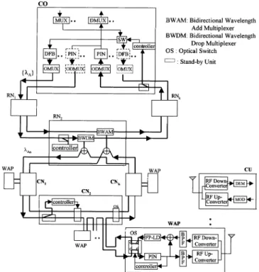
Fig. 1. A bidirectional path-protected ring architecture for DWDM/SCM broad-band fiber-wireless access networks.
premises. Moreover, a hybrid system, combining the benefits of fiber access networks and high-speed wireless solution, may address the issue of fiber availability by providing instant bandwidth to the end users [4]. In this letter, we propose a novel architecture for DWDM/SCM broad-band fiber-wireless access networks by combing fiber-to-the-MDU and broad-band wireless technologies. It is a hybrid access network that can offer an excellent solution for future subscriber loops.
II. ARCHITECTUREDESCRIPTION
Fig. 1 shows the two-level bidirectional path-protected ring (BPR) architecture for DWDM/SCM broad-band fiber-wireless access networks. In this architecture, the central office (CO) connects many remote nodes (RN) via a dual-fiber ring. Each RN cascade many wireless access points (WAP) through con-centration nodes (CN) and each WAP can serve many customer units (CU) wirelessly. The CO is equipped with two sets of de-vices: one for normal operation and the other for standby. It con-nects several RNs via a dual-fiber ring. An RN is composed of a protection unit (i.e., 95/5 coupler and controller), bidirectional wavelength add multiplexer (BWAM) and bidirectional wave-length drop multiplexer (BWDM). We use the multilayer di-electric interference filter to implement a wavelength add-drop
LIN et al.: A RELIABLE ARCHITECTURE FOR BROAD-BAND FIBER-WIRELESS ACCESS NETWORKS 345
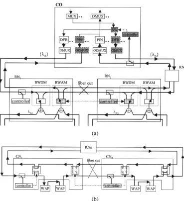
(a)
(b)
Fig. 2. The reconfiguration of CO, RN and CN under fiber failure (a) between RN and RN (b) between CN and CN .
multiplexer (WADM). This filter can be designed to transmit a specific wavelength and reflect all the other wavelengths. It can also be used to add or drop a single wavelength due to its bidi-rectional properties by adding simple optical switches (OS). In the normal operating condition, the CO transmits downstream signals in the counter-clockwise direction via RN and CN to the WAP. The WAP includes an optical transceiver, up/down RF converters and a sleeve antenna. Each WAP can provide a 5 MHz channel bandwidth at least and cover up to 16 CUs, which uses frequency division multiplexing (FDM) for multiple access and allocates 300 kHz of bandwidth per channel. Next, Only an ITU-T standard DFB laser transmitter should be used in the last WAP for each inter-CN ring. Here a CN can be used as a resi-dential signal collection node and a RN can be used as a busi-ness/enterprise concentration node.
Moreover, this architecture can perform self-healing func-tions under link failure. The self-healing schemes utilize a dis-tributed controller placed at each RN and each CN. The de-tailed reconfigurations under failure conditions are shown in Fig. 2. If fiber cut occurs between RN and RN as shown in Fig. 2(a), the controller at the CO and RN can detect the failure by monitoring the received optical signal and then si-multaneously trigger the RF switches at the CO and optical switches at the BWAM and BWDM . The CO can restore a set of standby devices (i.e., OMUX/ODMUX, DFB-LD module and PIN module) and reconfigure the ring network into two sep-arate rings. The standby OMUX transmits the optical signals for RN RN in the one ring while the optical signal for RN is still transmitted in the originally operating OMUX. If fiber cut occurs between CN and CN as shown in Fig. 2(b), again the controller at the CN can detect the failure and then trigger the optical switches at the CN and CN . The two separate rings are
Fig. 3. Experimental setup.
constructed and the up/downstream signals can be delivered to the CO via RNs adequately. Moreover, we put a 2 2 OS and controller to the each WAP. If one WAP fails, the retransmitted signals can be protected and go through other optical path. Con-sequently, the BPR is a high reliable architecture for fiber-wire-less network.
III. EXPERIMENTALSETUP ANDRESULTS
Our experimental setup is shown in Fig. 3. In the CO site, we use two eight-channel DWDM sets for optical multiplexing (OMUX) and demultiplexing (ODMUX). The channel spacing of DWDM is 1.6 nm and the isolation between adjacent chan-nels is 15 dB. The optical insertion loss for passing through the OMUX and ODMUX is 3.3 dB and 3.19 dB, respectively. In the upstream direction, four CUs linked to four WAPs and then connected to CO via two inter-CN rings and an inter-RN ring. In the downstream direction, three ITU grid DFB lasers with center wavelengths of 1547.72, 1549.32 and 1550.92 nm, are di-rectly modulated with a subcarrier frequency bandwidth covers 450–1000 MHz. The 1549.32 nm (i.e., ) and 1550.92 nm (i.e., ) wavelength signals are dropped to the intra-RN and intra-RN ring, respectively. The downstream 16-QAM subcar-rier frequencies are 466, 472 and 478 MHz, whereas the 472 MHz channel was monitored at the CU . In the upstream direc-tion, the 16-QAM subcarrier frequencies in four CUs are 134, 140, 146 and 152 MHz, whereas the 140 MHz channel was mon-itored at the DQAM . The data rate for each channel is up to 12 Mb/s for a 5-MHz bandwidth.
To estimate the scalability of the proposed network, we cal-culated the maximum size of the ring limited by the insertion losses of cascaded an OMUX and a number of RNs that in-clude PUs and BWDMs. According to tested results, the inser-tion losses of OMUX and RN are 3.3 dB and 2.7 dB ( ), respectively, fiber loss is 0.21 dB/km and 50/50 coupler loss is 3 dB. The optical power budget of an optical transceiver is about 34.5 dB under BER , dBm. The distance of each RN is about 1 km. Therefore, the maximum number of con-nectable RNs is up to 9 without optical amplifiers in the system ( ). If we increase the output power of DFB laser or put optical amplifiers into the network, the maximum number of RNs can be significantly in-creased.
The maximum number of cascaded WAPs in the inter-CN ring for each wavelength will be limited by accumulated optical noise and radio noise. According to our study, the RIN noise in
346 IEEE PHOTONICS TECHNOLOGY LETTERS, VOL. 15, NO. 2, FEBRUARY 2003
Fig. 4. The simulated and measured CNR versus OMI/channel for the upstream on the CO under fully operating conditions.
the receiver and nonlinear distortion induced by laser clipping are indeed critical parameters in the system if the number of active WAPs is large. Moreover, the laser modulation bandwidth is also a dominant factor that should be taken into consideration. In this application, we use commercial FP laser diodes with a modulating bandwidth of about 1 GHz in each WAP. Thus, the downstream signal frequency bandwidth is chosen from 450 to 900 MHz and the upstream signal frequency bandwidth ranges from 80 to 450 MHz, respectively. If 5 MHz is assigned to each subcarrier, more than 65 subcarrier channels (i.e., 65 WAPs) are available both in the upstream and downstream directions according to our simulated results. If each WAP can cover 16 CUs under 300 kHz channel spacing, the each inter-RN ring subnet can serve about 1040 CUs.
According to our design and implementation of WAP and CU, the performance of the RF module and optical transceiver are as following: RF range GHz GHz, WAP channel bandwidth 5 MHz, minimum RF received signal power
52 dBm, maximum RF received signal power 37 dBm, CNR dB under BER ; optical transmitter power output 3 dBm, input third-order intercept point (IIP3) 16 dBm. The required dynamic range for the uplink is 15 dB ( ). Thus, the minimum detectable signal will be 75 dBm ( ). If the RF transmitter power is 0 dBm, the maximum distance of WAP and CU is up to 50 meters in indoor environment. Next, The total noise must be less than 75 dBm at the receiver and the maximum acceptable equivalent input noise (EIN) of transceiver must be less than 135 dBm/Hz. Therefore, the spurious free dynamic range (SFDR) for the up-stream was calculated to be 56 dB-Hz [5].
The performance of the proposed network would be limited by the upstream transmission. Thus, we evaluated the upstream performance by using the carrier-to-noise ratio (CNR) at the re-ceiver of CO. The CNR is limited by various noise (RIN, shot and thermal) and distortion (nonlinear clipping and third order intermodulation) terms. Fig. 4 shows the simulated and mea-sured CNR versus OMI for the upstream channel. The max-imum CNR was measured to be 36 dB, which satisfied the dy-namic range requirement of 15 dB (CNR dB on the upstream).
To demonstrate the self-healing capability, we simulated a transmission failure at the location A (i.e., between RN and
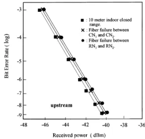
Fig. 5. The measured BERs for upstream transmission at the DQAM before and after fiber failure.
RN ) and location B (i.e., between CN and CN ), respectively. This network can automatically recover the fiber failure by mon-itoring the received optical signals. The CO can restore a set of standby devices and then reconfigure the ring network into two separate rings. The recovery time of this network was mea-sured to be less than 2 ms for 2 km inter-RN ring and 4 km inter-CN ring (the switching time of commercial RF switch and optic-fiber switch: 5 ns and 1 ms, respectively). Fig. 5 shows the measured bit-error rates (BERs) for upstream trans-mission at the output of DQAM before and after fiber failure under 12-Mb/s data rates and 10-meter distance between WAP and CU . The maximum power penalty after fiber failure at lo-cation A by passing through two RN ring subnets was less than 0.4 dB and at location B by passing through two CN ring subnets was less than 0.2 dB (BER ) . This experimental result can confirm and demonstrate the reliability of the proposed pro-tection method.
IV. CONCLUSION
We proposed the BPR architecture for DWDM/SCM broad-band fiber-wireless access network. It provided a flexible and reliable infrastructure for broad-band access. Experimental results show that this architecture can provide high capacity, excellent flexibility and reliability for future broad-band wireless access networks.
REFERENCES
[1] M. J. Rieaenman, “The rebirth of radio,” IEEE Spectrum, pp. 62–64, Jan. 2001.
[2] P. P. Iannone, K. C. Reichmann, A. Smiljanic, N. J. Frigo, A. H. Gnauck, L. H. Spiekman, and R. M. Derosier, “A transparent WDM network fea-turing shared virtual rings,” J. Lightwave Technol., vol. 18, no. 12, pp. 1955–1963, Dec. 2000.
[3] P. Arijs, R. Meersman, W. Vanparys, E. Iannone, A. Tanzi, M. Pierpaoli, F. Bentivoglio, and P. Demeester, “Architecture and design of optical channel protected ring networks,” J. Lightwave Technol., vol. 19, no. 1, pp. 11–22, Jan. 2001.
[4] K. Biesecker, “The promise of broadband wireless,” IEEE Networking, pp. 31–38, November/December 2000.
[5] RF and Microwave Fiber-Optic Design Guide, Agere Systems Inc., Al-lentown, PA, 2001.