TECHNICAL NOTE
Method for measuring
the retardation of a wave plate
Lih-Horng Shyu, Chieh-Li Chen, and Der-Chin Su
An electro-optic modulator applied to a carrier frequency is used to measure the retardation of a wave plate. This method is not only suitable for any wave plate but also can be operated in real time.
Wave plates are often used in optical metrology, for example, ellipsometry1-3 and phase-shifting
interfer-ometry.4,5 The retardation error of a wave plate will
significantly influence the experimental results.6
Several papers on measuring the retardation error of a wave plate have been published. Some of them are overly complicated7-10; others can be used only to
measure the quarter-wave plate11 or the wave plate
for the wavelength of a commercial He-Ne Zeeman laser.12 A novel method for measuring the
retarda-tion of a wave plate, based on the general concept of converting an optical phase difference into an electri-cal phase difference,13,14 is presented in this Technical
Note. An electro-optic modulator is used to mix a carrier frequency to the reference signal and the test signal. Then, when the phase difference between two signals is measured, the retardation of the wave plate is measured.
A schematic diagram of the optical system is shown in Fig. 1. The linearly polarized light passing through an electro-optic modulator EO is incident on a beam splitter BS and is divided into two parts: the refer-ence beam and the test beam. The referrefer-ence beam reflected from BS passes through an analyzer ANr,
then enters the photodetector Dr, whereas the test
beam transmitted through BS passes through a tested wave plate W and an analyzer ANt and is detected by
another photdetector Dt. For convenience the +z
axis is in the propagation direction and the y axis in the vertical direction. Let the incident light be linearly polarized in the horizontal direction. The fast axis of EO under an applied electric field and the
fast axis of the wave plate are both at 45° to the x axis. Both the transmission axes of two analyzers ANr and
ANt are along the y axis.
Let the amplitude of the reference beam be normal-ized to 1; then the Jones vector15 of the reference
beam is
The authors are with the Institute of Electro-Optical Engineer-ing, National Chiao-Tung University, 1001 Ta-Hseuh Road, Hsin-Chu, Taiwan, China.
Received 13 April 1992.
0003-6935/93/224228-03$06.00/0. © 1993 Optical Society of America.
Fig. 1. Schematic diagram for measuring the retardation of a wave plate: EO, electro-optic modulator; BS, beam splitter; W, tested wave plate; AN, analyzer; D, photodetector; ESPU, elec-tronic signal processing unit.
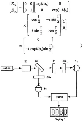
where Г is the phase introduced by the electro-optic modulator and φx and φy are the phase shifts for the x
component (p polarization) and y component (s polar ization) of the reflection beam from BS, respectively. The Jones vector of the test beam is
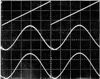
Fig. 2. Recorded signals without the tested quarter-wave plate: upper trace, external modulated signal; middle trace, reference signal; lower trace, test signal.
where a is the amplitude of the test beam relative to the reference beam, α is the constant phase difference produced by the optical path difference between two beams, and δ is the retardation to be measured. Hence the intensities of the reference signal and the test signal are
respectively. From Eq. (3) it is obvious that the intensity of the reference signal is independent to the phase shifts corresponding to the reflection from BS. If Г is constant, i.e., without the electro-optic modula tor or with the electro-optic modulator off, both Ir and It are unchanged, and it is difficult to evaluate the
value of δ. If one applies a sawtooth signal to the electro-optic modulator with an amplitude that is sufficient to cause a total phase change of 2π during one cycle, then Г = (wt, where w is the angular frequency of the sawtooth. Thus the detector out put signals become sinusoidal with a phase difference of δ. Moreover these two sinusoidal signals are sent to the electronic signal processing unit (ESPU) as shown in Fig. 1. Finally the phase difference be tween these two signals is measured, and the retarda tion can be obtained with high accuracy.
To show the feasibility of this technique, a quarter-wave plate (WPQ-6328-4M) manufactured by Japan Sigma Koki Ltd. was tested. A He-Ne laser with a 632.8-nm wavelength and an electro-optic modulator (PC 100/2), manufactured by Electro-Optics Develop ments Ltd. with a half-wave voltage of 250 V, were used in this test. For easier observation these sig nals were monitored by an oscilloscope and are shown in Figs. 2 and 3. The upper parts of these two figures represent the external modulated sawtooth
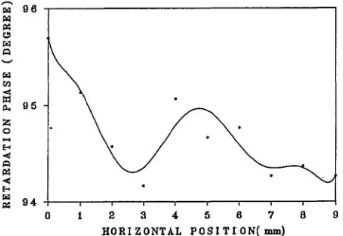
signal, which is applied to a electro-optic modulator with a frequency of 200 Hz. The middle and lower parts represent the wave forms of reference signals and test signals, respectively. From Fig. 2 one can see that the reference and test signals are inphase before the tested wave plate is located in the setup. In Fig. 3 it is clear that they have a phase difference after the introduction of the tested wave plate. The phase difference is easily read out with a digital phase meter. The results of 10 points across that quarter-wave plate are shown in Fig. 4; the average retarda tion is 94.7°, and the rms deviation is 0.46°.
In this Technical Note we presented an easy method for measuring the retardation of a wave plate. It is not only suitable for any wave plate but also has great accuracy and can be operated in real time. If a wave plate for any other wavelength is to be tested, the
Fig. 3. Recorded signals with the tested quarter-wave plate: upper trace, external modulated signal; middle trace, reference signal; lower trace, test signal.
Fig. 4. Results of 10 points across the tested quarter-wave plate.
measurement processes are the same as above except that the light source should be converted to the corresponding wavelength.
This study was supported in part by the National Science Council, Taiwan, China, under contract NCS-79-04170-E009-13. We also thank D. R. Huang and J. B. Horng, Opto-Electronics and System Labora-tory, Industrial Technology Research Institute, Hsin-chu, Taiwan, for their help.
References
1. H. Takasaki, "Photoelectric measurement of polarized light by means of an ADP polarization modulator," J. Opt. Soc. Am. 51,461-462(1961).
2. R. M. A. Azzam and N. M. Bashara, Ellipsometry and
Polar-ized Light (North-Holland, Amsterdam, 1977), Chap. 5, p. 364.
3. P. S. Hauge and F. H. Dill, "Design and operation of ETA, an automated ellipsometer," IBM J. Res. Dev. 17, 472-489 (1973).
4. D. C. Su and L. H. Shyu, "Phase shifting scatter plate interferometer using a polarization technique," J. Mod. Opt. 38, 951-959 (1991).
5. J. H. Bruning, "Fringe scanning interferometers," in Optical
Shop Testing, D. Malacara, ed. (Wiley, New York, 1978), pp.
409-437.
6. M. P. Kothiyal and C. Delisle, "Polarization component phase shifters in phase shifting interferometry: error analysis," Opt. Acta 33, 787-793 (1986).
7. H. G. Jerrard, "Optical compensators for measurement of elliptical polarization," J. Opt. Soc. Am. 38, 35-59 (1948). 8. H. G. Jerrard, "Transmission of light through birefringent
and optically active media: the Poincaré sphere," J. Opt. Soc. Am. 44, 634-640 (1954).
9. R. C. Plumb, "Analysis of elliptically polarized light," J. Opt. Soc. Am. 50, 892-894 (1960).
10. B. R. Grunstra and H. B. Perkins, "A method for the measure-ment of optical retardation angles near 90 degrees," Appl. Opt. 5, 585-587 (1966).
11. C. M. Mclntyre and S. E. Harris, "Achromatic wave plates for the visible spectrum," J. Opt. Soc. Am. 58, 1575-1580 (1968). 12. Y. Lin, Z. Zhou, and R. Wang, "Optical heterodyne
measure-ment of the phase retardation of a quarter-wave plate," Opt. Lett. 13,553-555(1988).
13. H. F. Hazebroek and A. A. Holscher, "Interferometric ellipsometry," J. Phys. E 6, 822-826 (1973).
14. R. Calvani, R. Caponi, and F. Cisternino, "Real-time hetero-dyne fiber polarimetry with narrow- and broad-band sources," J. Lightwave Technol. LT-4, 877-883 (1986).
15. A. Yariv and P. Yeh, Optical Waves in Crystals (Wiley, New York, 1984), Chap. 5, p. 121.