A Neural Fuzzy Network Approach to
Radar Pulse Compression
Fun-Bin Duh, Chia-Feng Juang, Member, IEEE, and Chin-Teng Lin, Senior Member, IEEE
Abstract—To make good range resolution and accuracy
com-patible with a high detection capability while maintaining the low average transmitted power, pulse compression processing giving low-range sidelobes is necessary. The traditional algorithms such as the direct autocorrelation filter (ACF), least squares (LS) in-verse filter, and linear programming (LP) filter based on three-element Barker code (B13 code) have been developed. Recently, the neural network algorithms were issued. However, the traditional algorithms cannot achieve the requirements of high signal-to-side-lobe ratio and low integrated sidesignal-to-side-lobe level (ISL), and the normal neural networks such as the backpropagation (BP) network usu-ally produce the extra problems of low convergence speed and are sensitive to the Doppler frequency shift. To overcome these defects, a new approach using a neural fuzzy network to deal with pulse compression in a radar system is presented. Two different Barker codes are carried out by a six-layer self-constructing neural fuzzy network (SONFIN). Simulation results show that this neural fuzzy network pulse compression (NFNPC) algorithm has significant ad-vantages in noise rejection performance, range resolution ability, and Doppler tolerance, which are superior to the traditional and BP algorithms.
Index Terms—Barker code, neural fuzzy network, pulse
com-pression.
I. INTRODUCTION
O
NE OF THE main purposes of waveform design forpulse compression in a radar system is to solve the dilemma between the range resolution and the pulse length. Pulse compression processing is one of the most important factors in determining the performances of a high-resolution and/or high-detection radars. For instance, a synthetic aperture radar (SAR) always contains a high range resolution pulse compression, and a downward-looking rain measuring radar with a range sidelobe level of 55 dB is also required [1], [2]. In a satellite-borne rain radar, very stringent requirements on range sidelobe level of 60 dB are demanded [3], and the air traffic control system requires the sidelobe lower than 55 dB under the mainlobe level [4]. In addition, some researchers have devoted themselves to developing the pulse compression algorithms for this century’s advanced weather radar to meet the higher time and space resolution requirements [5]–[9]. Eventually, the main purpose of the pulse compression is to raise the signal-to-maximum sidelobe (signal-to-sidelobe) ratio (SSR) and decrease the integrated sidelobe level (ISL) which is defined as [7] to improve the detection and range resolution
Manuscript received November 8, 2002; revised October 17, 2003. C. F. Juang is with the Department of Electrical Engineering, National Chung-Hsing University, Taichung 402, Taiwan, R.O.C.
F. B. Duh and C. T. Lin are with the Department of Electrical and Control Engineering, National Chiao-Tung University, Hsinchu, Taiwan, R.O.C.
Digital Object Identifier 10.1109/LGRS.2003.822310
abilities of the radar system. Also, for a good pulse compression algorithm, certain performance must be considered, including the noise rejection and the Doppler tolerance performance. Here, the sidelobes are unwanted by products of the pulse compression process; for the correlation of a code, the sidelobes are the portions of the output waveform nonmatching with the code other than the output of matching the code. And the sidelobe level is the magnitude of the sidelobe.
There are two basic waveform designs suitable for pulse com-pression: frequency-coded and phase-coded waveforms, which are also candidate waveforms for weather radar application [7]. The performance comparison between the basic waveforms de-scribed above is given in [5] and [10]. The Barker-based binary phase codes have better range resolution than the frequency-coded waveforms at the price of higher loss and higher sidelobes [8], [9]. In this letter, we consider only Barker-based binary phase codes because of the ease in implementation.
Ackroyd and Ghani [11] have developed an optimum mis-matched filter for the B13 code sidelobe suppression in the least square (LS) sense, and Steven Zoraster has utilized linear programming (LP) techniques to determine the optimal filter weights for minimizing the peak range sidelobes of the Barker code [12]. Hua et al. [13] tried to combine the advantages of Ri-haczek’s matched filter [14] and Zoraster’s linear programming methods to obtain a new Barker code sidelobe suppression algorithm. Recently, neural networks applied to pulse compres-sion were proposed with their learning capabilities [15], [16]. Kwan and Lee [15] have employed a backpropagation (BP) algorithm to realize pulse compression with a phase-coded waveform, and obtained a good result. But the convergence speed of the BP algorithm is inherently low [16] and sensitive to the Doppler frequency shift. To cope with the drawbacks, a novel solution to the problem of pulse compression has been proposed in this work. It is a self-constructing neural fuzzy inference network (SONFIN) that we previously proposed in [17]. We use SONFIN to perform a B13 code with the sequence
and a 20-element
combined Barker code (CBC) expanded by combining known Barker code with the sequence [18]
The algorithm combines the Barker code with SONFIN to constitute the neural fuzzy network pulse compression (NFNPC). The use of SONFIN in the proposed NFNPC 1545-598X/04$20.00 © 2004 IEEE
and parameter learning simultaneously such that it can online construct itself on the fly dynamically. As a result, it can always find itself a very economic size of network for a given learning task while comparing the other neural fuzzy network.
The rest of this letter is organized as follows. Section II gives the problem statements. In Section III, we shall introduce the structure of the SONFIN and the way the SONFIN used to process the pulse compression in radar system. In Section IV, we present the performances of pulse compression for NFNPC. Discussion and conclusion are made in Sections V and VI, respectively.
II. PROBLEMFORMULATION
To apply the simplest type of phase code, the biphase code, we subdivide the transmitted pulse of duration into sub-pulses of duration . The direct autocorrelation func-tion (ACF) can be represented mathematically
phase
phase (1)
Equation (1) can be separated to two parts as follows:
(2)
(3)
When expanding (2) and (3), we can obtain a matrix form
.. .
.. .
(4) The vector in the right-hand side of (4) is the replica of the transmitted code. Alternatively they are the weightings for the received signal sequence. That is, we can express the above
equation as , where matrix is formed by the
shifting of the input sequence and is a weighting vector. Observing the matrix , it defines patterns, and the proper code word is in the th pattern. However, we must con-sider an additional null sequence, , meaning no input signal exists. Subsequently there are different sequences that may be encountered in the input of a pulse compression network. Ex-cept the output of proper code word sequence is 1, the others are expected 0. Thus, the problem in acquiring the output sequence with high SSR and low ISL of pulse compression can be con-sidered as a mapping of the received input sequences
input sequences (5)
With the advantages described as in Section I, SONFIN is very suitable for this nonlinear mapping relationship.
III. PULSECOMPRESSIONUSING ANEURALFUZZYNETWORK
A. Use of SONFIN to Process the Pulse Compression in a Radar System
The block diagram of the digital pulse compression system using NFNPC is shown in Fig. 1. The Barker code generator generates the B13 code sequences or the 20-element CBC se-quences, which are sent to RF modulator and transmitter. Re-ceived IF signals are passed through a bandpass filter matched to the subpulse width and are demodulated by two detections, I_det and Q_det, with a local-oscillator (LO) signal at the same IF frequency, and then the in-phase (I) and quadrature (Q) channel echo signals are detected, respectively. These echo signals are converted to digital form by analog-to-digital (A/D) converters under the system timing control that also clocks the Barker code to be transmitted. The digital form of the echo signals consists of the Barker code and interfering noise. The NFNPCs, which are implemented by the trained SONFIN, carry out the pulse compression based on the received sequence. Once the echo se-quence is matched with the transmitted Barker code, the output of each SONFIN will be 1 with one subpulse duration. When the SSR of the NFNPC output is very high, the false alarm of the detector is reduced, and eventually the detection ability of the radar system is enhanced.
Fig. 1. Block diagram of the digital pulse compression system using NFNPC.
B. SONFIN
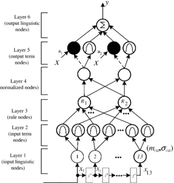
The structure of SONFIN for B13 code is shown in Fig. 2. There are no rules initially in the SONFIN. They are created and adapted as online learning proceeds via simultaneous struc-ture and parameter learning, so the SONFIN can be used for normal operation at any time as learning proceeds without any assignment of fuzzy rules in advance. This six-layered network realizes a fuzzy model of the following form:
Rule IF is and and
is is
where is the fuzzy set of the th linguistic term of input variable , is the center of a symmetric membership function on , and is the consequent parameter. The SONFIN consists of nodes, each of which has some finite fan-in of connections represented by weight values from other nodes and fan-out of connections to other nodes. Associated with the fan-in of a node is an integration function that serves to combine information, activation, or evidence from other nodes. This function providing the net input for the
node is ,
where are inputs to this node, and
are the associated link weights, and denotes the activation function. The superscript in the above equation indicates the layer number. We shall describe the functions of the nodes in each of the six layers of the SONFIN as follows.
Each node in Layer-1 corresponds to one input variable and only transmits input values to the next layer directly. That is . In Layer-2, each node corresponds to a linguistic label (small, large, etc.) of one of the input variables in Layer-1. We choose Gaussian membership function to specify the degree to which an input value belongs to a fuzzy set. The operation
performed in this layer is ,
where and are, respectively, the center (or mean) and the width (or variance) of the Gaussian membership function of the th partition for the th input variable . Hence, the link weight in this layer can be interpreted as . To repre-sent the firing strength of the corresponding fuzzy rule, we use the nodes of Layer-3 to represent fuzzy logic rules and perform precondition matching of rules. These nodes are combined by
AND operation and expressed as , where
is the number of Layer-2 nodes participating in the IF part of
Fig. 2. Structure of the SONFIN for pulse compression by three-element Barker code.
the rule. Layer-4 is used to normalize the firing strength and
expressed as , where is the number
of rule nodes in Layer-3. The consequent output is calculated in Layer-5. The input variables plus a constant construct the linear combination of the node operation. Thus, the whole
func-tion performed by this layer is .
Finally, the node of Layer-6 integrates all the actions recom-mended by Layer-5 and acts as a defuzzifier with the expression
of , where is the number of nodes in Layer-5.
Two types of learning, structure and parameter learning, are used concurrently for constructing the SONFIN. A detailed de-scription of the overall learning algorithms can be found in [17]. IV. SIMULATIONRESULTS ANDPERFORMANCEEVALUATIONS
This section illustrates the performances of the proposed NFNPC by comparing it with BP, direct autocorrelation filter (ACF), least squares (LS) inverse filter, and linear programming (LP) filter based on B13 code, and comparing it with ACF and BP based on 20-element CBC, respectively. We used the SSR and ISL to evaluate the performances of these algorithms.
A. Training the SONFIN and Convergence Performance
The SONFIN is repeatedly trained offline with the training set being composed of the 26 time-shifted sequences of the B13 code [15], The training data are generated by simulating the received sequence of a true B13 code as well as a {0} sequence that represents radar has not received any information yet. In these training sequences, the desired output of the SONFIN, , is 1 when the proper Barker code just presenting in the input and is 0 otherwise.
The 20-element CBC is used for another examination simulation. Both the SONFIN and BP networks are repeatedly trained offline with the training set being composed of the 40
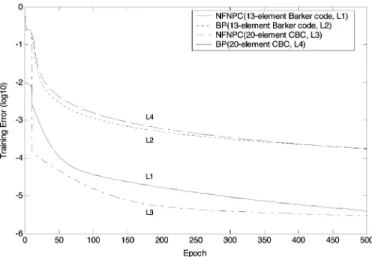
Fig. 3. Convergence curves of NFNPC and BP for the three-element Barker code and the 20-element combined Barker code.
time-shifted sequences of the CBC, respectively. The training criteria are as same as training the B13 code sequences, and the training error is low to 2.97 10 for NFNPC. The convergence curves of NFNPC and BP algorithms for the B13 code and the 20-element CBC are shown in Fig. 3.
B. Noise Robustness
The input signals used to evaluate the noise robustness are generated by a B13 code and a 20-element CBC, and both of them are perturbed by additive white Gaussian noise with five
different noise strengths, ,
respec-tively. The noise performance comparison results of the ACF, LS, LP, BP, and NFNPC algorithms on SSR and ISL with dif-ferent noise environments are shown in Table I for B13 code, and the results of the ACF, BP, and NFNPC algorithms for 20-element CBC are shown in Table II.
C. Range Resolution Ability
The range resolution ability is the examination of the ability to distinguish between two targets solely by measurement of their ranges in a radar system. To resolve two targets in range, the basic criterion is that the targets must be separated by at least the range equivalent of the width of the processed echo pulse.
To compare the range resolution ability, two targets that are separated from two subpulses delay-apart to five subpulses delay-apart are simulated, and the SSR and ISL from the out-puts of these algorithms are examined, respectively. Table III shows the range resolution ability comparison of the ACF, LS, LP, BP, and NFNPC algorithms using B13 Code by two targets with different subpulse delay-apart on SSR and ISL without additive noise. Table IV shows the range resolution ability comparison of the ACF, BP, and NFNPC algorithms using 20-element CBC by two targets with different subpulse delay-apart on SSR and ISL without noise.
D. Doppler Tolerance
The Doppler sensitivity is caused by the shifting in phase of individual elements of the phase code by the target Doppler, so that, in the extreme, if the last element is shifted by 180 ,
TABLE II
NOISEPERFORMANCECOMPARISON OF THEACF, BP,ANDNFNPC ALGORITHMSUSING20-ELEMENTCOMBINEDBARKERCODE ONSSRANDISL
WITHDIFFERENTNOISEENVIRONMENTS(INMEANVALUEOVER100 RUNS)
the code word is no longer matched with the replica. To ex-amine the Doppler tolerance of the pulse compression algo-rithms in this letter, we assume that a B13 code with the pulse width of 26 s and each subpulse width of 2 s is transmitted. If the target echo is with Doppler shift of 20 kHz (approxi-mately Mach 0.9 to an X-band radar), the period of Doppler cycle is 50 s. Since the phase shift across the 13-element code is 180 , the last subpulse in received Barker code is effectively inverted [19]. That is, the input sequence of pulse
compres-sion is changed from to
. All of these results of comparisons between ACF, LP, LS, BP and NFNPC algo-rithms are shown in Fig. 4(a). For the 20-element CBC, if the target echo is with Doppler shift of 12.82 kHz, the last sub-pulse in received CBC is effectively inverted. All of these results of comparisons between ACF, BP, and NFNPC algorithms are shown in Fig. 4(b).
E. Response to the Dispersed Pulse Echo
To compare the compression response of the NFNPC, BP, and ACF algorithms to the dispersed pulse echo from meteorolog-ical radar, a simulation procedure for step signal is adopted from [9]. Given that the time spacing between samples is equal to the subpulse duration , each subpulse in the transmit pulse de-fines a range bin. At sample-time index , the sample can be
represented as , , and ,
where is the number of range bins, and is the number of subpulses. As the construction procedure explained in [9], the output range cell can be mathematically described as
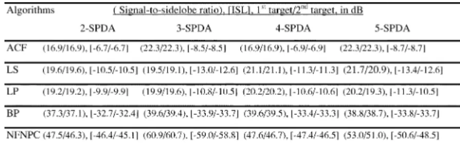
TABLE III
RANGERESOLUTIONABILITYCOMPARISON OF THEACF, LS, LP, BPANDNFNPC ALGORITHMS OFTWOTARGETSUSING
13-ELEMENTBARKERCODEWITHDIFFERENTSUBPULSEDELAY-APART(SPDA)ONSSRANDISL
TABLE IV
RANGERESOLUTIONABILITYCOMPARISON OF THEACF, BP,ANDNFNPC ALGORITHMS OFTWOTARGETSUSING
20-ELEMENTCOMBINEDBARKERCODEWITHDIFFERENTSUBPULSEDELAY-APART(SPDA)ONSSRANDISL
Fig. 4. Compressed waveforms of a target echo for (a) using BC13 code with Doppler shift 20 kHz for the NFNPC, BP, ACF, LS, and LP algorithms, and for (b) using 20-element combined Barker code with doppler shift 12.82 kHz for the NFNPC, BP, and ACF algorithms.
For the B13 code, the number of range bins
is 26, and the sequence of the output cell is The results of comparisons between NFNPC, BP, and ACF algorithms are shown in Fig. 5.
V. DISCUSSION
Tables I and II show that NFNPC has higher SSRs and lower ISLs than any other compared algorithms either in noise-free or in high-density noisy environments for using B13 code and 20-element CBC. These results provide evidence that the NFNPC can reduce the range sidelobe level low to 61 dB. Meanwhile, NFNPC has a better noise rejection ability. This is because the NFNPC is achieved first by efficiently partitioning the input and output spaces into clusters through learning proper fuzzy terms for each input/output variable, and then
Fig. 5. Simulation results of NFNPC, BP, and ACF algorithms for the step-dispersed echo.
by optimally constructing fuzzy rules through finding proper mapping between input and output clusters.
It is clear in Tables I and II that the SSRs and ISLs are better while using the longer CBC than using the shorter B13 code for NFNPC, but only a little improvement is noted for traditional BP algorithm. The main reason is that the NFNPC can obtain a lower training error while using 20-element CBC than using B13 code, but the BP algorithm cannot. This can be seen from Fig. 3. However, this justifies that a phase code with longer code word has better SSR and ISL for NFNPC and BP algorithms, whether there is noise in the received code sequence or not. Moreover, the SSrs and ISLs are worse while using 20-element CBC than using B13 code for the traditional ACF algorithm. This is because the 20-element CBC achieves higher sidelobe levels than B13 code.
As examining range resolution of two targets, Table III shows that the NFNPC has higher SSRs and lower ISLs than any other compared algorithms for two targets separated from two sub-pulses delay-apart to five subsub-pulses delay-apart. Table IV shows
are sensitive to the Doppler shift produced by a moving target. Among them, the normalized output of BP algorithm is obviously higher than any other algorithms at the 19th time delay (the 19th subpulse). That is, when BP algorithm is used as the pulse compression processor, a moving target echo with Doppler shift more than 20 kHz will generate a false target just next to the true one. The similar results for using CBC are shown in Fig. 4(b).
Form the simulation results shown in Fig. 5, we obtain that the intelligent algorithms, NFNPC and BP, can detect the dis-persed echo to be point-like target. This is a very distinguishing feature. When the dispersed duration excluded, it is obvious that the NFNPC algorithm has superior SSR and ISL for dispersed echo.
When the computational complexity is considered for B13 code, the ACF algorithm needs 12 additions, 4 multipliers, and one floating-point memory unit, the LS algorithm needs 11 ad-ditions, 4 multipliers, and 4 floating-point memory units, the LP algorithm needs 12 additions, 12 multipliers, and 8 floating-point memory units, the BP algorithm needs 42 additions, 46 multipliers, 4 sigmoid functions, and 46 floating-point memory units, and the SONFIN algorithm needs 79 additions, 82 multi-pliers, 2 exponential functions, and 80 floating-point memory units. It is obvious that the SONFIN has more computation complexity than any other compared algorithms, and this is its disadvantage.
VI. CONCLUSION
A neural fuzzy network, SONFIN, for radar pulse compres-sion is proposed in this letter. This algorithm is called neural fuzzy network pulse compression, NFNPC. The success is due to the combinations of the self-constructing neural fuzzy in-ference network and both the short, simple, ease-implementing B13 code and 20-element CBC, respectively. Simulations have demonstrated that the sidelobe at the output of NFNPC can be significantly decreased. Moreover, while compared with tradi-tional algorithms such as ACF, LS, LP, and BP, NFNPC has
[2] A. Tanner, S. L. Durden, R. Denning, E. Im, F. K. Li, W. Ricketts, and W. Wilson, “Pulse compression with very low sidelobes in an airborne rain mapping radar,” IEEE Trans. Geosci. Remote Sening, vol. 32, pp. 211–213, Jan. 1994.
[3] H. D. Griffiths and L. Vinagre, “Design of low-sidelobe pulse compres-sion waveforms,” Electron. Lett., vol. 30, no. 12, pp. 1004–1005, June 1994.
[4] J. P. Larvor, “Digital pulse compression with low range sidelobes,” in
Proc. Int. Conf. Radar, 1992, pp. 391–394.
[5] J. M. Ashe, R. L. Nevin, D. J. Murrow, H. Urkowitz, N. J. Bucci, and J. D. Nespor, “Range sidelobe suppression of expanded/compressed pulses with droop,” in Proc. 1994 IEEE Int. Radar Conf., Atlanta, GA, Mar. 29–31, 1994, pp. 116–122.
[6] C. A. Hwang and R. J. Keeler, “Sample phase aspects of FM pulse com-pression waveforms,” in Proc. IGARSS, 1995, pp. 2126–2128. [7] R. J. Keeler and C. A. Hwang, “Pulse compression for weather radar,”
in Proc. IEEE Int. Radar Conf., May 1995, pp. 529–535.
[8] N. J. Bucci, H. S. Owen, K. A. Woodward, and C. M. Hawes, “Validation of pulse compression techniques for meteorological functions,” IEEE
Trans. Geosci. Remote Sensing, vol. 35, pp. 507–523, May 1997.
[9] A. S. Mudukutore, V. Chandrasekar, and R. J. Keeler, “Pulse compres-sion for weather radars,” IEEE Trans. Geosci. Remote Sensing, vol. 36, pp. 125–142, Jan. 1998.
[10] D. K. Barton and S. A. Leonov, Radar Technology
Encyclo-pedia. Norwell, MA: Artech House, 1997.
[11] M. H. Ackroyd and F. Ghani, “Optimum mismatched filters for side-lobe suppression,” IEEE Trans. Aerosp. Electron. Syst., vol. AES-9, pp. 214–218, Mar. 1973.
[12] S. Zoraster, “Minimum peak range sidelobe filters for binary phase-coded waveforms,” IEEE Trans. Aerosp. Electron. Syst., vol. AES-16, pp. 112–115, Jan. 1980.
[13] X. H. Chen and O. Juhani, “A new algorithm to optimize Barker code sidelobe suppression filters,” IEEE Trans. Aerosp. Electron. Syst., vol. AES-26, pp. 673–677, July 1990.
[14] A. W. Rihaczek and R. M. Golden, “Range sidelobe suppression for Barker codes,” IEEE Trans. Aerosp. Electron. Syst., vol. AES-7, pp. 1087–1092, Nov. 1971.
[15] H. K. Kwan and C. K. Lee, “A neural network approach to pulse radar detection,” IEEE Trans. Aerosp. Electron. Syst., vol. 29, pp. 9–21, Jan. 1993.
[16] K. D. Rao and G. Sridhar, “Improving performance in pulse radar detec-tion using neural networks,” IEEE Trans. Aerosp. Electron. Syst., vol. 31, pp. 1194–1198, July 1995.
[17] C. F. Juang and C. T. Lin, “An on-line self-constructing neural fuzzy inference network and its applications,” IEEE Trans. Fuzzy Syst., vol. 6, pp. 12–32, Feb. 1998.
[18] J. L. Eaves and E. K. Reedy, Principles of Modern Radar. New York: Van Nostrand Reinhold, 1987.