ELECTROCHEMICAL SOCIETY LETTERS
Re-examination of Pressure and Speed Dependences of
Removal Rate during Chemical-Mechanical
Polishing Processes
Wei-Tsu Tseng*
National Nano Device Laboratories, Hsinchu 300, Taiwan
Ving-Lang Wang
Institute of Electronics, National Chiao-Tung University, Taiwan
ABSTRACT
A new removal rate model which is a modification to the Preston equation is developed to re-account the dependence of removal rate
on the down force (pressure) and rotation speed during the chemical-mechanical polishing (CMP) process. The removal rate is first expressed as a linear function of both normal and shear stresses. The analogy of the CMP removal process to traveling indenters is con-sidered and the stresses acting upon the abrasive particles (indenters) are formulated using previous models based on principles of
elas-ticity and fluid mechanics. An expression is then derived which predicts the (pressure)5'6 and (speed)112 dependences of the removal rate.
Experimental results with thermal oxides are consistent with the predictions.
Chemical-mechanical polishing (CMP) has been widely recog-nized as the most promising method that achieves both local and global planarization for ultralarge scale integrated circuit (ULSI)
manufacturing processes.t'2 The polishing (material removal) mechanism is still obscure however and the process control and basic understanding of this technology remain essentialy on the empirical level. So far most CMP users and researchers adopt Preston's equation3 to monitor removal rate. This equation incor-porates the pressure (I and speed ( as the main contributors to
removal rate (R.R.)
R.R.=CPV
[1]Or more generally it can be expressed as
= C5(F/A)(AsIt
where zT/zt is the change in thickness over time t (i.e., removal
rate); F/A is the total applied force F over area A on which the pol-ishing (abrasion) occurs; Es is the relative travel distance between
sample surface and pad; and C, is the Preston coefficient related to chemical erosion processes and material charcteristics. Both
Eq. 1 and 2 suggest that the removal rate depnds equally on
pres-sure and speed.
Originally proposed for glass polishing, the Preston equation is also of experimental nature and no analytical work has been pub-lished to verify or to challenge it. Runnels and Eyman4 took into account the normal stress (a',,) and shear stress ('r) acting on a point during polishing
R.R. =
The normal stress acting on the abrasive particles against the samples originates from the pressure imposed by the polish arm while the shear stress arises from the slurry flow across the sam-ple surface activated by relative motion between the rotating pad and carrier. Further development of Eq. 3 requires the determina-tion of stress distribudetermina-tions, which involves delineadetermina-tion of several active mechanisms including fluid flow and solid deformation.The contribution of fluid flow to stresses4 and erosion5 during CMP operations have been analyzed. Nevertheless a more general
* Electrochemical Society Active Member.
model combining fluid flow and solid deformation (wearing) is still
lacking.
Cook6 perceived the removal process as a traveling indenter plowing across the wafer surface.The abrasive particles transport-ed in by the turbulent slurry encroach upon and indent into the
wafer surface. The indentation process is considered Hertzian and
the resulting stresses can be calculated from principles of elastic mechanics. The force F acting on a spherical particle of diameter
d in the particle/wafer contact can be calculated as67
F =
[4]2K
where Kis particle fill fraction which is unity for a fully filled closed
121 packing, and P is the pressure. The normal stress o, can then be
expressed as the force F divided by the contact area between the polishing particle and the sample surface 'Trr
F
[5] in which the radius of contact i can be determined from theories
of contact mechanics8
= {()[( u2) + (1
u2)]}v3 [6] where i,, v', are the Poisson's ratios of sample surface and the
par-ticle and Eand E' are elastic moduli of the sample and parpar-ticle, [3] respectively.
Runnels5 related the feature-scale erosion model to the Preston
equation and formulated the stresses due to slurry flow. In his model, the shear stress T can be approximated as
TC[V]C
[7] where is the dynamic viscosity, A is the sample surface areabeing polished, and C is a constant related to the chemical aspects
of the process. Equation 7 is derived based on the tribological approximation for slider bearings9 and the shear stress T
repre-J. Electrochem. Soc., Vol. 144, No.2, February 1997 The Electrochemical Society, Inc. L15
) unless CC License in place (see abstract).
ecsdl.org/site/terms_use
address. Redistribution subject to ECS terms of use (see
140.113.38.11
Fig. 1 .The dependence of removal rate on carrier speed (V) under given pressures (P). The data are fitted to Eq. 8. Refer
to text for details.
sents the speed at which the polished residues are dissolved in
and transported away by the flowing slurry.1°
Combining Eq. 3 through 7, a new expression of removal rate in
terms of pressure and rotational speed emerges
R.R. = MP516 [8]
where Mis a constant associated with materials properties, slurry
concentration, and chemical processes during CMP.
The expression for removal rate in Eq. 8 is markedly different from that in Eq. 1. While the P516 dependence of R.R. in Eq. 8 is
close to Preston's prediction, the V112 term in Eq. 8 apparently
sug-gests a much weaker dependence of removal rate on speed V Notice that, on a particle scale, the V term in Eq. 8 should corre-spond to the speed that a fixed point on the wafer experiences
relatve to slurry flow. It is directly associated with the relative
motion between pad and carrier.
To verify the validity of Eq. 8, CMP experiments are performed
with 1 p.m thick thermal dioxide samples grown on 200 mm silicon waters using IC1000/Suba IV pads mounted on a polishing platen.
SC-i slurry consisting of fumed silica suspension dispersed in
aqueous potassium hydroxide (pH -- 10.3) is distributed across the
pad at a flow rate of 200 sccm. Pad conditioning is performed between each wafer to rejuvenate the pad surface features. Pad speed is fixed at 20 rpm while pressure and carrier speed are
var-ied to examine their respective effects on removal rate. Oxide thick-ness is measured by Nanospec at 17 points across wafers and the
removal rate is calculated from thickness differences averaged over the 17 points before and after each polish.
The removal rate data are plotted against carrier speed in Fig. 1 under varied pressure. The data are fitted to Eq. 8 with constant P.
As illustrated, the agreement with the prediction in Eq. 8 is
excel-lent. Removal rate exhibits a V112 dependence over a wide pressure
range. The calculated M values from the fitted curves using Eq. 8
are listed in Table I. Mincreases as more pressure is being applied
on the wafers. This implies that the chemical erosion process is accelerated under high pressures. This acceleration may not be indefinite however, since, under a high enough pressure, the pad surface feature flattens and the slurry holding capability deterio-rates,10 which slows the chemical erosion process, leading to a drop in removal rate.
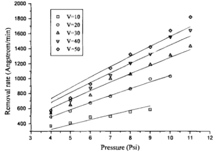
Figure 2 shows the pressure dependence of removal rate.
Pressure was varied from 4 to ii psi while carrier speed was set
at 10, 20, 30, 40, and 50 rpm. The data are fitted to Eq. 8 with con-stant carrier speed. At high pressure and high carrier speed, removal rate does exhibit a P5t6 dependence. However, at low
pres-sure and high carrier speed, removal rate is lower than that
pre-dicted from Eq. 8. This may result because under the above
situa-tion (high t low F), many abrasive particles are carired away by the flowing slurry before they can indent into the wafers.
The significance of the results above is the re-examination of the polish mechanism.The material removal model in Eq. 8 originates
from the particle-scale stress formulation in Eq. 3, 5, and 7, rather
than the wafer-scale parameters such as pressure and speed used in the Preston equation. Cook's model deals with the mechanics of
polishing particles from the theory of elasticity but does not take into account the contribution of the flowing slurry, although the moving particle analogy adopted by Cook implies slurry motion.
Runnels5 approaches the polish (removal) problem from principles of fluid mechanics based on two-dimensional Navier-Stokes
equa-tions but does not relate the fluid motion to actual material-break-ing mechanisms from principles of solid mechanics. The model developed herein not only provides the linkage between fluids
motion and material wearing but also quantifies CMP removal rate
in terms of simple mechanical parameters (P and V). In addition, it re-examines the scientific basis of the Preston equation which has been long established. The abrasive particles are first being
indented into the polished wafers to cause plastic deformation.The residues from the indentation are then carried away by the flowing slurry to complete a removal cycle.
Notice that, on the particle scale, the V term in Eq. 8 should not be a constant throughout a single removal cycle. It is a complex
function of the difference between pad and carrier speeds, and the relative distance between pad and carrier. In addition, it varies radi-ally on the waters. In Fig. 1, since the pressure and pad speed are
held constant, the variation in carrier speed reflects the overall
trace the points on a wafer experience during the removal process. Simulation work is currently in progress regarding the speed distri-bution and polish nonuniformity across the wafers.
The derivation of Eq. 8 proceeds from a pure mechanics
view-point. Similar to the Preston equation, the introduction of the
para-meter Mto represent the contribution of chemical erosion to the overall removal rate in Eq. 8 inherently hypothesizes that material removal processes due to mechanical abrasion and chemical ero-sion are mutually independent. However, the data in Table I indi-cate that Mis not constant. It is, at least, slightly pressure-depen-dent as it increases from 28.614 A/psi at P = 4 to 34.963 A/psi at
P = 11. Such pressure-enhanced chemical erosion is probably the consequence of stress-assisted chemical attack by the aggressive slurry. Such a phenomenon may be more prominent in metal CMP as stress corrosion12 is known to occur in most metals. Under 7 psi
(-.-48260 Pa), the normal stress acting on a 0.3 mm silica particle in SC-i slurry is Ca. 46 MPa (--6672 psi),1° which falls within the range where stress corrosion of metals occurs. Additionally, the speed Vmay exert certain influences on the chemical erosion rate as erosion corrosion12 is known to depend strongly on the flow of
Table I. Calculated M parameter from the fitted curves in Fig. 1 based on Eq. 8.
7 8
30.176 31.157 32.520 33.832
2000
L16 J. Electrochem. Soc., Vol. 144, No.2, February 1997 The Electrochemical Society, Inc.
I
01 V=tO 01 V-20 V-30 V=40o
v-so 0Carrier speed (rpm) Pressure (Psi)
Fig.2. The dependence of removal rate on pressure under
given carrier speeds (V). The removal rate data are fitted to P5t6 as in Eq. 8. P (psi) M(Alpsi) 4 28.614 5 6 9 10 11 33.837 34.499 34.963
) unless CC License in place (see abstract).
ecsdl.org/site/terms_use
address. Redistribution subject to ECS terms of use (see
140.113.38.11
J. Electrochem. Soc., Vol. 144, No. 2, February 1997 The Electrochemical Society, Inc. Li 7
corrosive agent (or, in the present case, slurry). Based on the
above perspectives, Eq. 8 can be modified further into the expression
R.R. = M(F V)P516V11
The functional dependences of M on P and V may exist in a complicated fashion and is a subject of further investigation.
In conclusion, this article presents a new removal rate model for chemical-mechanical polishing based on combined solid and fluid
mechanics.The removal process can be perceived as that an
abra-sive particle indents into the wafers before the indented residues are transported away by slurry motion. The new model predicts (pressure)5t6 and (speed) dependences of removal rate, different
from the Preston equation. Experimental removal rate data obtained with 200 mm wafers are consistent with the new model's prediction.
Acknowledgment
This work was supported by the National Science Council under
Contract No. NSC 85-2622-E009-O1 1. Manuscript received Nov. 5, 1996.
National Nano Device Laboratories assisted in meeting the pub-lication costs of this article.
REFERENCES
1. W. L. Guthrie, W. J. Patrick, E. Levine, H. C. Jones, E. A.
Mehter, T. F. Houghton, G. T. Chiu, and M. A. Fury, IBM J.
[9] Res. Develop., 36, 845 (1992).
2. I. Ali, S. R. Roy, and G. Shinn, Solid State Technol., 37(10), 63 (1994).
3. F. Preston, J. Soc. Glass TechnoL, 11, 247 (1927).
4. S. R. Runnels and L. M. Eyman, This Journal, 141, 1698 (1994).
5. 5. R. Runnels, ibid., p. 1900.
6. L. M. Cook, J. Non-Cryst. Solids, 120, 152 (1990).
7. N. Brown, P. Baker, and R. Maney, Proc. SPIE, 306, 42 (1981).
8. B. Lawn and R.Wilshaw, J. Mater. Sci., 10, 1049 (1975). 9. R. D. Davies, P. B. Arnell, and T. L. Whomes, Tribology
Prin-ciples and Design Applications, p. 124, Springer-Verlag,
New York (1991).
10. W.-T. Tseng, C-W. Liu, B.-T. Dai, and C.-F. Yeh, Thin Solid
Films, In press.
11. C.-W. Liu, Ph.D. Thesis, p. 104, National Chiao-Tung University, Hsinchu, Taiwan (1996).
12. M. G. Fontana, Corrosion Engineering, 3rd ed., McGraw-Hill,
New York (1986).
Potentiometric Investigation of Silicon Electrode
Immersed in Alkaline Hydrogen Peroxide Solution
Containing Trace level of Iron
Oliver M. R. Chyan,* Jin-Jian Chen, Ligang Chen,** and Fei Xu**
Department of Chemistry, University of North Texas, Denton, Texas 76203, USA
ABSTRACT
Sensing electrodes derived from the regular silicon wafer were shown to respond sensitively to the part-per-billion level of iron impu-rities in alkaline hydrogen peroxide solution (frequently referred to as standard clean-i solution).The potentiometric results clearly indicate that the large positive shift of silicon open-circuit potential mainly originates from the adsorbed iron impurities on the surface oxide layer. Acid treatments by HCI or HF effectively regenerate the iron-contaminated silicon sensing electrode.
Introduction
Alkaline hydrogen peroxide solution (NH4OH/H202/H20) was first
developed by Kern in 1967 to remove adsorbed organic contami-nants from silicon wafer surfaces.1 Although the exact formulation may vary, this frequently referred standard clean-i (SC-i) solution is still widely used in large quantity as an effective organic clean-ing solution for the preparation of ultraclean silicon substrates for
microelectronic device fabrication. The organic cleaning function is achieved through a dynamic balance between oxide formation and etching which simultaneously takes place on the wafer top surface
in alkaline hydrogen peroxide solution. The adsorbed organics (especially particles) can be detached during these face-lifting oxi-dation/etching cycles and effectively removed from the silicon
sur-face. However, there are two major drawbacks arising from the
SC-1 treatment. First, the nonuniform chemical etching can enhance undesirable microscopic scale surface roughening. Second, a trace level of metal impurities (especially iron) from NH4OH/H202 aqueous solution can easily contaminate the silicon wafer surface to strongly degrade the minority carrier lifetime and cause prema-ture breakdown of gate oxide.2
Recently, we reported that direct open-circuit potential
measure-ments on a silicon-based sensing electrode provide a sensitive method for directly monitoring ultratrace [part per billion-part per trillion (ppb-ppt)] metallic impurities in HF-related solutions.5 The unique feature of this new detection methodology is that the sens-ing electrode was derived directly from the regular silicon wafer. Consequently, the Si-based sensor was designed to respond selectively only to contaminants which react with the silicon wafer
* Electrochemical Society Active Member. ** Electrochemical Society Student Member.
surfaces. We report here the potentiometric investigation of the
sil-icon electrodes immersed in various NH4OH/H202 solutions. Our potentiometric data demonstrate that detection of part-per-billion level of iron impurities is feasible in the highly basic and oxidizing SC-i solution using a silicon wafer-based sensing electrode. In
contrast to the direct metal deposition on the silicon surfaces in HF
solution,5 our data demonstrate that the observed positive silicon
potential shift originates from the trace level of iron impurities
adsorbed by the thin surface chemical oxide layer formed during
the NH4OH/H202 cleaning treatment.
Experimental
All the potentiometric measurements were carried out using pre-viously described procedures.5 Briefly, a computer interfaced, high
impedance potentiometer was used in conjunction with a double-junction standard Ag/AgCI reference electrode to measure the open-circuit potential of the silicon electrodes immersed in various SC-i solutions. The silicon electrodes were prepared from
boron-doped Czochralski (CZ) wafers, The electrical contact was made to
the back side of the silicon chip using Ga/In eutectic (99.99%, AESAR). Prior to each potentiometric experiment, the silicon elec-trode was etched by hydrofluoric acid (4.9%, electronic grade) and immersed in the SC-i solution for 30 mm to cover the silicon sur-face with chemical oxide. A followup HF etching (5 mm, 4.9%)
was employed if the hydrogen terminated silicon surface is
required. The Fe3/SC-i solutions were prepared in precleaned Telfon labwares through dilution of a concentrated Fe3 ICP
stan-dard solution (Aldrich) with electronic grade SC-i solution
(NH4OH/H202/H20, 1:1:30). A typical potentiometric experiment involves measuring the base line potential for 60 mm in the clean
) unless CC License in place (see abstract).
ecsdl.org/site/terms_use
address. Redistribution subject to ECS terms of use (see
140.113.38.11