立即咬合受力之人工牙根的研發與生物力學分析 (1/3)
Development and Biomechanical Analysis of Immediately Loaded
Implant (1/3)
計畫編號: NSC98-2320-B-039-005-MY3 執行期限:98 年 8 月 1 日至 99 年 7 月 31 日 主持人:黃恆立 中國醫藥大學牙醫系 [email protected] 共同主持人:陳遠謙 中國醫藥大學附設醫院口腔外科 林殿傑 中國醫藥大學 口腔衛生學系 一、中文摘要 本研究結合逆向工程-快速原型技術與有線 元素分析探討下顎後牙區立即咬合人工植牙的生 物力學行為。本研究建構了共18組電腦人工牙根 模型(包含六種外型設計與三種表面粗糙度),下顎 骨使用非等向性之材料性質,並於人工牙根支台 上方,給定兩種負荷條件(130牛頓),一為垂直向 下,一為與牙根中心軸夾角45度之斜向力。此外, 本研究另建構一組體外實驗模型,進行驗證分 析。結果顯示人工牙根的外型與表面處理的粗糙 度,的確會對立即咬合受力的牙根牙根,其周圍 骨質之應力(應變)造成影響,人工牙根-骨質之間 的界面滑移量而言,有無螺紋設計相當重要,特 別是有螺紋設計之人工牙根(與圓柱型、階梯形人 工牙根相比較)具有明顯降低界面滑移量,有助於 提高人工牙根之初始穩定度。 關鍵詞:立即咬合人工植牙、人工牙根外型設計、 表面處理、骨應力(應變)、人工牙根-骨 質之間界面滑移量。 AbstractExperiment with rapid prototyping technique and validation finite element model were performed to evaluate the biomechanical behavior of an immediately loaded mandibular implant. Also, 18 finite element models of 6 implant designs and 3 surface roughnesses with anisotropic bone material properties were analyzed to compare the bone stresses and the sliding at the bone-implant interface under a vertical or lateral force of 130 N. The results shows that bone stress (strain) of an immediately loaded implant are heavily dependent on the implant design and surface roughness. For improving the initial interfacial interlocking using a threaded implant has a higher priority than using cylindrical or step designs with a rough surface for an immediately loaded implant.
Keywords: immediately loaded implant, implant design, surface roughness, bone stress (strain),
sliding between implant and bone
二、緣由與目的
Many techniques have been used to produce various types of microroughness structures on the implant surface, such as sandblasting, plasma spraying, and porous beading [1]. Although the usefulness of a rough surface texture in implants for immediate loading procedures has been suggested [2], a deeper understanding is required of the effects of surface texture of immediately loaded implants on micromotion at the BII (Bone to Implant Interface, BII) and the stress distribution in bone. Implant macrodesign has been regarded as essential to the success of an immediately loaded implant [3]. For example: using screw-type implants enhance more contact area in BII and improved implant stability [3]. stepped implant and the tapered body of threaded implant have also been proposed that mimic the root anatomy and enhance the bony support in spongy bone, thereby creating a favorable load distribution [4,5]. In addition, the size and shape of the thread might affect the stress pattern in the surrounding bone [6,7]. Therefore, The present study compared the biomechanical effects of immediately loaded implants with various designs of implant shapes and designs of surface textures with different roughnesses in the edentulous mandible. 三、研究方法
Rapid prototyping and impression modeling
A resin model of the posterior mandible was constructed by using the rapid prototyping (RP) technique and the impression procedures. The CAD model of the human cortical bone created by A series of computed tomography (CT) images of the posterior mandible was exported as a stereolithography file that was loaded into the 3D printer of an RP machine (ZPrinter 310plus, Z Corporation, Burlington, MA, USA) with zb56 binder and zCast 501 powder to create prototypes of cortical bone (Fig. 1 a) [15]. However, because the RP model produced by the 3D printer is a powdered
fabrication, drilling a hole and screwing an implant into the model can break the structure. Therefore, the cortical shell of the posterior mandible needed to be duplicated again using alginate impressions from RP model with temporary crown of acrylic resin (Tempron, GC, Tokyo, Japan). Then an epoxy resin was filled in to the core of the model of cortical shell to produce a replica of the trabecular bone (Fig. 1 a). A self-tapping implant (3.75 × 13 mm) (ICE® self-tapping implant, 3i Implant Innovation, Palm Beach, FL, USA) was then inserted into the resin model for attaching the cylindrical abutment (implant temporary hexed cylinder, 3i Implant Innovation) (Fig. 1 b).
Mechanical testing
A self-developed jig was designed with an adjustable rotational screwing device so that a 45-degree lingual oblique force could be applied in the experiments. Each loading mode involved applying a force of 130 N to the cylindrical abutment using a universal testing machine (JSV-H1000, Japan Instrumentation System, Nara, Japan) with a head speed of 1 mm/min. Rectangular rosette strain gauges (KFG-1-120-D17-11L3M3S, Kyowa) were attached to the buccal and lingual sides of the crestal cortical region around the implant (Fig. 1a) using cyanoacrylate cement (CC-33A, Kyowa). Signals corresponding to the three independent strains εa, εb, and εc measured by the
three gauges comprising the rosette strain gauge were sent to a data acquisition system (NI CompackDAQ, National Instruments, Austin, TX, USA) and analyzed by the associated software (LabVIEW SignalExpress 3.0, National Instruments). Each measurement was repeated three times. The maximum (εmax) and minimum (εmin)
principal strains were obtained.
Finite element analysis
Six implant models (4 × 15 mm) comprising cylindrical, stepped, v-thread, rectangular threaded, and tapered body of threaded implants, and an implant with two thread sizes, were constructed by CAD software of SolidWorks (Fig. 2). All models were combined using Boolean operations, and the IGES format of the solid model was then imported into ANSYS Workbench (Swanson Analysis, Huston, PA, USA) to generate the FE model (Fig. 3) using 10-node tetrahedral h-elements (ANSYS SOLID187 elements).
Four conditions of surface textures of the BII were simulated. In accordance with Grant et al. [1], titanium-based surface configurations of polished, Al2O3-blasted, plasma-sprayed, and beaded porous
surfaces were analyzed. The frictional coefficients (μ) between human trabecular bone and those four implant surface textures were approximately 0.4, 0.68, 1.0, and 1.0, respectively. These values were
then specified for the nonlinear surface-to-surface contact elements (ANSYS CONTA174 and TARGE170 elements) to simulate the sliding and sticking of frictional contact behavior.
Anisotropic material properties of cortical and trabecular bone were adopted in the FE models [8], whereas the materials of the implant and the prosthetic crown were assumed to be isotropic and linearly elastic [9]. Two types of loading conditions were simulated: (1) a vertical force applied to the central fossa and (2) a lingual oblique force applied at 45 degrees to the long axis of the implant on the buccal cusp. In both cases the applied load was 130 N. The inferior surfaces of the mandibular bone were constrained to zero displacement in the x, y, and z directions as the boundary condition (Fig. 3 a).
The convergence of the FE models was tested to verify the mesh quality, with the convergence criterion set to a change in the peak von-Mises stress of bone for different element sizes of less than 3%. Based on the results of the convergence test, an element size of 0.4 mm was applied for meshing in all FE models. In addition, to validate the nonlinear FE model (Fig. 3 b and 3 c), a cylindrical abutment was created and μ at the BII was set to 0.3. The boundary condition and the material properties (Table 1) were identical to those in the in-vitro experiment test.
Fig. 1. (a) Three-dimensional RP model of the cortical shell (lower object) used to mode the resin into the model of cortical bone. The epoxy resin was poured into the core of the cortical bone to fabricate the model of trabecular bone (upper-right object). Strain gauges were attached to the bone surface Table 1. Young’s modulus and Poisson’s ratio of materials of the experimental model.
Material Young’s modulus E (MPa) Poisson’s ratio ν Resin (Tempron, GC co.) 2979 0.4 Epoxy resin 223 0.4 Titanium 110000 0.3
around the implant on both the buccal and lingual sides (upper-left object). (b) Self-tapping implant (D = 4 mm and L = 13 mm) with a cylindrical abutment.
Fig. 2. Solid models of the (a) cylindrical, (b) stepped, (c) v-thread, (d) rectangular threaded, (e) tapered body of threaded implants, and (f) implants with two thread sizes.
Fig. 3. (a) Vertical loading and lateral loading were analyzed in FE models. The boundary condition involved fixing the inferior surface of the mandible (arrowheads). (c) Isometric and (d) sectional views (in the mesial-distal direction) of the validation FE model.
四、結果與討論
E
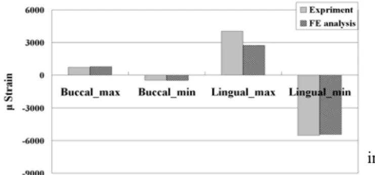
xperimental versus validated FE modelsFigure 4 compares the maximum (tensile) and minimum (compressive) principal strains of the experimental and validation FE models in both the buccal and lingual regions of crestal cortical bone. The errors in strains between two models are 8% (εmax at buccal side) and 2% (εmin at buccal side) as
well as 32% (εmax at lingual side) and 2% (εmin at
lingual side) in the lateral loading. Overall, the experimental and validation FE models demonstrated similar strain patterns.
Fig. 4. Maximum and minimum principal strains in
the experimental and validation FE models under the lateral loading.
Bone stress analysis & evaluation of sliding at the BII
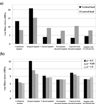
The peak von-Mises stresses of cortical bone and trabecular bone around the 6 implants as well as the highest sliding distances between bone and immediately loaded implants with various roughness surfaces were listed in Table.3. The von-Mises stress distributions in cortical bone (Fig. 5) showed that the stresses were highest at the crestal region around the implant; otherwise, the high bone stresses were found near the valley of the threads, the apex of the implant, and the stepped areas where the implant’s diameter changed in the stepped implant (Fig. 5). The stress in the bone around the immediately loaded implant was considerably higher fo r lateral loading than for vertical loading (Fig. 6 a). The stresses in cortical bone (144.9 MPa) and trabecular bone (20.8 MPa) were highest in the cylindrical and stepped implants, respectively. The stresses in bone were more than 20% higher when using the stepped implant in the lateral loading mode, but they were at least 15% lower than those in the cylindrical implant (Fig. 6). In general, bone stresses were lower in threaded implants than in cylindrical and stepped implants (Table 3, Fig. 6). The stress in trabecular bone and the sliding at the BII were 17–25% and 16–48% lower in the rectangular threaded implant than in the v-thread implant, respectively (Fig. 6 b). The stress in cortical bone did not appear to differ between the tapered body and the straight body of threaded implants (with same rectangular thread). However, the stress in trabecular bone was 15–25% higher in the tapered body of threaded implant than in the straight body of threaded implant (Fig. 7 a). However, the stress in cortical bone in the tapered body of threaded implant increased (by less than 15%) during vertical loading but decreased (by less 10%) during lateral loading except in the models with μ = 0.4 (Fig. 6). The stresses in cortical bone
did not differ in the implant with two thread sizes. Nevertheless, the peak stress in trabecular bone was about 15% lower in the implant with two thread sizes than in the v-thread implant with μ = 0.4 (Fig.
7 a). Increasing the frictional coefficient of the BII in the cylindrical implant and stepped implant increased the stress in cortical bone and reduced the stress in trabecular bone, but in the threaded implant this did not always increase the stress in cortical bone but clearly decreased the stress in trabecular bone (Figs. 6 b and 7 b).
Fig. 5. von-Mises stress distributions in cortical bone (a) and trabecular bone (b) in models with μ = 0.4 at
the BII under lateral loading.
Fig. 6. Peak von-Mises stresses in cortical bone in models with μ = 0.4 at the BII under vertical and
lateral loadings (a), and in models with μ = 0.4, 0.68,
and 1.0 at the BII only under lateral loading (b).
Fig. 7. Peak von-Mises stresses in trabecular bone in all models with μ = 0.4 at the BII under vertical and
lateral loadings (a), and in models with μ = 0.4, 0.68,
and 1.0 at the BII only under lateral loading (b).
Evaluation of sliding at the BII
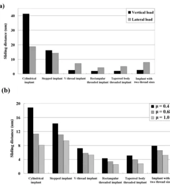
The sliding at the BII peaked (at 41.3 μm) in the cylindrical implant at the crestal region (Table 3, Fig. 8) during vertical loading (Fig 9 a). Otherwise, a high degree of sliding was also observed at the apex of implant and at the threads near the apex of the implant (Fig. 8). Sliding at the BII in both cylindrical and stepped implants (Fig. 9 b) was at least 20% lower for the Al2O3-blasted implant
surface (μ = 0.68) than for the polished implant
surface (μ = 0.4). Likewise, sliding at the BII was
more than 35% lower for the plasma sprayed (μ =
1.0) and beaded porous (μ = 1.0) implant surfaces
(Fig. 9 b). Threading the implant surface obviously reduced the interfacial sliding at the BII (Table 3, Fig. 9 a) during both vertical and lateral loading. Increasing μ from 0.4 to 0.68 and from 0.4 to 1.0
decreased sliding at the BII in threaded implants by 10−28% and 16−45%, respectively. Sliding at the BII was 16−50% lower in the square-shape threaded implant than in the v-thread implant. Using a tapered body design slightly increased sliding at the BII (especially during lateral loading) relative to a rectangular threaded implant (straight-body design). Reducing the thread pitch in cortical bone did not significantly affect sliding at the BII relative to the v-thread implant (Fig. 9).
Fig. 8. Distributions of sliding at the BII in 6 implant models with μ = 0.4 under lateral loading (a), and in
cylindrical implants with μ = 0.4, 0.68, and 1.0 (left
to right, respectively) under vertical loading (b) and lateral loading (c).
Fig. 9. Peak sliding at the BII in models with μ = 0.4
under vertical and lateral loadings (a), and in models with μ = 0.4, 0.68, and 1.0 only under lateral loading
(b).
This study revealed the biomechanical mechanisms (including bone stress and sliding at the BII) of immediately loaded mandibular implants with various implant designs and surface roughnesses. The FE models could be limited by the oversimplified loading conditions and the inhomogeneous material properties of human bone. Nevertheless, within the limitations of this study, the following conclusions can be drawn:
1. Both experimental and validated FE analyses confirm that the immediately loaded implant can induce disproportionate bone stresses during lateral loading, which might results in a high risk of surrounding bone loss due to
overloading resorption.
2. Adding threading to an implant can significantly decrease the bone stress and sliding at the BII relative to nonthreaded implants (in cylindrical and stepped implants). 3. The stress in trabecular bone and sliding at the BII are lower for the rectangular threaded implant than for the v-thread implant. Using shorter threads in cortical bone decreases sliding at the BII but not bone stresses.
4. The stress reduction in cortical bone and sliding at the BII does not differ significantly between threaded implants with tapered and straight bodies, and stresses in trabecular bone are higher in the tapered body of threaded implant.
5. It is not purely advantageous for the implant surface texture to have a high roughness (such as produced by plasma spraying or a beaded porous surface), since this decreases sliding at the BII it increases the crestal bone stress around the implant.
五、計畫成果自評
本研究計劃的第一階段已經成功針對六種人工 牙根的外型(包含: cylindrical, stepped, v-thread, rectangular threaded, tapered body of threaded implants, 與 implants with two thread sizes)與四種 表 面 處 理 的 方 式(包含: polished, Al2O3-blasted,
plasma-sprayed, and beaded porous surfaces)進行分 析,並針對所得之結果,進行第二年進階的研究, 因此第二年之研究重點將著重不同骨質密度下立 即咬合受力人工植牙的表面,此外,近年來人工 牙根的表面處理方式日新月異,新型表面處理方 式,例如:陽極處理、噴砂加上酸蝕、噴砂加上陽 極處理…等等方式,尚未有任何研究報告,探討 其表面摩差係數,並進階進行電腦模擬分析,亦 將是明年度計畫探討的要點之一。 本研究計劃於今年第一階段所研究之成果,已 成功發表於兩岸三地、國際研討會,並投稿於國 際期刊,兩篇已獲得刊登,另一篇已被接受,成 果豐碩,如下所示: 兩岸三地研討會 黃恆立, 傅立志, 陳遠謙, 傅沐杰, 許瑞廷. “植 體外型與表面粗糙度對立即咬合植體之生物力學 分析”, 中華民國家庭牙醫學會兩岸三地大會, 2009. 國際研討會
Heng-Li Huang, Lih-Jyh Fuh, Jui-Ting Hsu,
Michael YC Chen. “Biomechanical analysis of various shapes and surface roughnesses of an
immediately loaded implant_3D Finite element simulation”, World Congress 2009-Medical Physics and Biomedical Engineering, Munich, Germany, 2009.
國際期刊
Heng-Li Huang*, Jui-Ting Hsu, Lih-Jyh Fuh,
Dan-Jae Lin, Michael YC Chen. “Biomechanical Simulation of Various Surface Roughnesses and Geometric Designs on an Immediately Loaded Dental Implant”, Computers in Biology and Medicine, 40:525-532, 2010. (SCI) (Corresponding author)
Heng-Li Huang, Ming-Gene Tu, Lih-Jyh Fuh,
Yuan-Chien Chen, Chu-Lung Wu, Shou-I Chen, Jui-Ting Hsu*. “Effects of elasticity and structure of trabecular bone on the primary stability of dental implants”, Journal of Medical and Biological Engineering, 30:85-89, 2010. (SCIE & EI)
Heng-Li Huang, Yin-Yu Chang, Dan-Jae Lin,
Yu-Fen Li, Kuan-Ting Chen, Jui-Ting Hsu*, “Initial stability and bone strain evaluation of the immediately loaded dental implant: an in vitro study”, Clinical Oral Implants Research, Accept, 2010. (SCI)
The mark of “*” represents corresponding author 六、參考文獻
[1] J.A. Grant, N.E. Bishop, N. Gotzen, C. Sprecher, et al. “Artificial composite bone as a model of human trabecular bone: The implant–bone interface”, J. Biomech. 40:1158-1164, 2007.
[2] R. Uribe, M. Penarrocha, J. Balaguer, N. Fulgueiras, “Immediate loading in oral implants. Present situation”, Med. Oral. Patol. Oral. Cir.
Bucal. 10:E143-153, 2005.
[3]
N. Sykaras, A.M. Iacopino, V.A. Marker, R.A. et al., “Implant materials, designs, and surface topographies: their effect on osseointegration. A literature review”, Int. J. Oral. Maxillofac. Implants. 15:675-690, 2000.[4] C. Maiorana, F. Santoro, “Maxillary and mandibular bone reconstruction with hip grafts and implants using Frialit-2 implants”, Int. J.
Periodontics. Restorative. Dent. 22: 221-229, 2002.
[5] G.h. Nentwig, “Ankylos implant system: concept and clinical application”,
J. Oral.
Implantol.
30:171-177, 2004.[6] S. Hansson, M. Werke, “The implant thread as a retention element in cortical bone: the effect of thread size and thread profile: a finite element study”,
J. Biomech. 36:1247-1258, 2003.
[7] H.L. Huang, C.H. Chang, J.T. Hsu, A.M. Fallgatter, et al., “Comparison of implant body designs and threaded designs of dental implants: a
3-dimensional finite element analysis”, Int. J. Oral.
Maxillofac. Implants. 22: 551-562, 2007
[8] A.M. O'Mahony, J.L. Williams, P. Spencer, “Anisotropic elasticity of cortical and cancellous bone in the posterior mandible increases peri-implant stress and strain under oblique loading”,
Clin. Oral. Implants. Res. 12:648-657, 2001.
[9] H.L. Huang, J.T. Hsu, L.J. Fuh, M.G. Tu, et al. “Bone stress and interfacial sliding analysis of implant designs on an immediately loaded maxillary implant: A non-linear finite element study”, J. Dent 36:409-417, 2008.